

M
M
X
X--
3
3
0
0
0
0
4
4
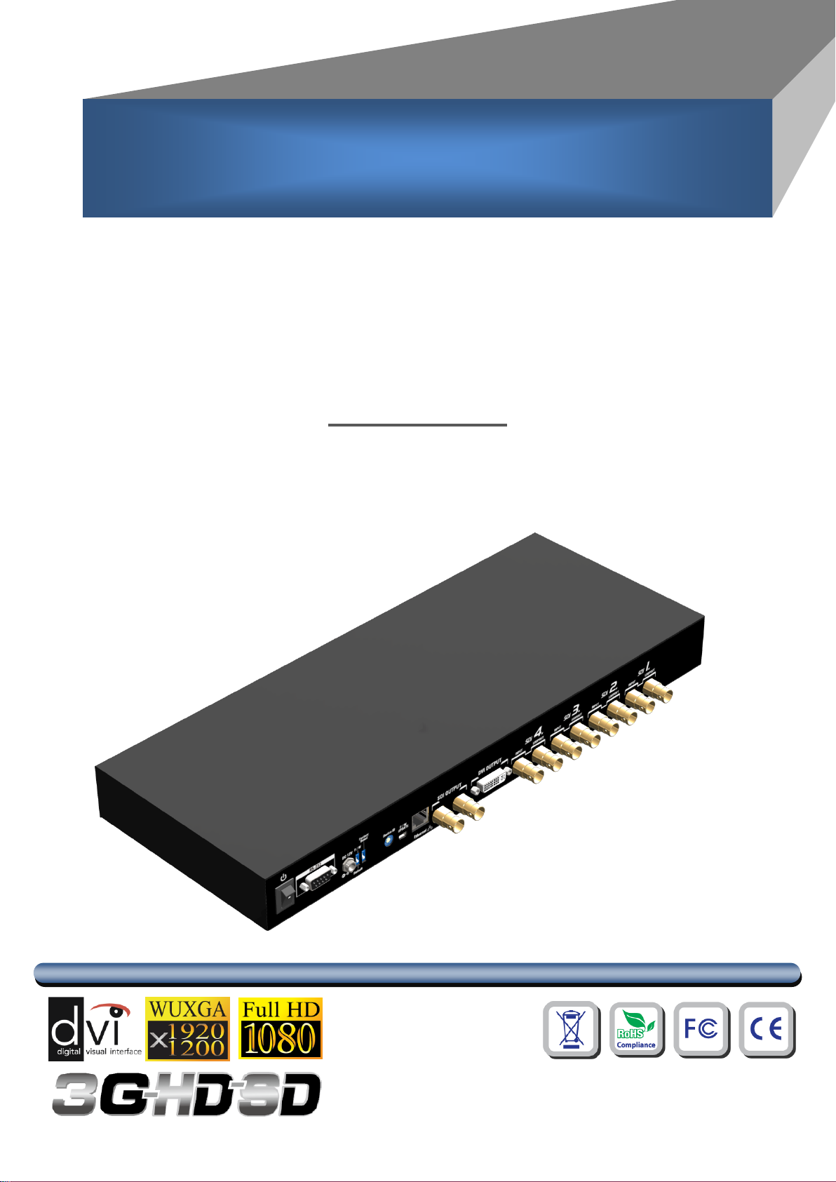
3G/HD/SD-SDI Quad-view
Video Processor
User Manual
The MX-3004 3G/HD/SD-SDI Quad-view Video Processor has been tested for conformity to safety
TABLE OF CONTENTS
INTRODUCTION..................................................................................................................... 1
FEATURES ............................................................................................................................. 1
PACKAGE CONTENTS .......................................................................................................... 1
SPECIFICATIONS .................................................................................................................. 2
PANEL DESCRIPTIONS ........................................................................................................ 3
APPLICATION DIAGRA ......................................................................................................... 4
HARDWARE INSTALLATION ................................................................................................ 5
OPERATION SOFTWARE ..................................................................................................... 6
TROUBLE SHOOTING ......................................................................................................... 17
LIMITED WARRANTY .......................................................................................................... 18
regulations and requirements, and has been certified for international use. However, like all
electronic equipments, the MX-3004 should be used with care. Please read and follow the safety
instructions to protect yourself from possible injury and to minimize the risk of damage to the unit.
● Follow all instructions and warnings marked on this unit.
● Do not attempt to service this unit yourself, except where explained in this manual.
● Provide proper ventilation and air circulation and do not use near water.
● Keep objects that might damage the device and assure that the placement of this unit is on a
stable surface.
● Use only the power adapter and power cords and connection cables designed for this unit.
● Do not use liquid or aerosol cleaners to clean this unit. Always unplug the power to the device
before cleaning.

1
INTRODUCTION
The MX-3004 3G/HD/SD-SDI Quad-view Video Processor is an advanced video processor for
multimedia presentations. It is an ideal solution for some applications such as surveillance, where up to
four SDI video signals must be displayed on a single display. It supports up to 4 SDI video inputs, of which
four can be outputted simultaneously with the desired display layout through software control. The
advanced video processor allows you to manipulate output images, wherever positions and whatever
sizes you want for viewing two computers or two video signals or a combination.
The embedded processor converts signals from input sources to match the native resolution of
monitors, flat panel displays, projectors as well as user-selectable output settings up to WUXGA
(1920x1200). Dual outputs are provided in both digital (SDI) and digital (DVI) format, one is connected to
remote display and the other is connected to on-site display for real time monitoring.
FEATURES
Supports 3G/HD/SD SDI video formats
Input resolutions support interlaced or progressive video under SMPTE.
Dual outputs DVI(640x480 to 1920x1200) / SDI(720P, 1080P)
Each SDI channel has 1 re-clocked SDI loop-outs.
Adjustable size& position through software.
Image parameters and layouts are automatically saved in flash memory and can be recalled
for later use.
User-selectable output settings, up to 1920x1200(Only for DVI).
Perfectly as a video screen splitter, a video converter and a video switcher.
Firmware upgradable for support of new features and technology enhancements.
Software control through RS-232.
Control protocol available for customer proprietary design
1U size.
PACKAGE CONTENTS
1x MX-3004
1x USB to RS-232 cable
2x 1U rack mounting-ear
1x Installation software CD
1x UL 12V power adapter
1x UL AC power cord
1x User Manual
2
SPECIFICATIONS
Model Name
MX-1004S
MX-3004
Technical
Role of usage
Multiplexer / video processor
Dual output support
Yes [DVI & VGA]
Yes [DVI & SDI]
Background video
input
No
No
Video bandwidth
Composite [13.5MHz]
SDI [2.97Gpbs & 2.97/1.001Gbps]
DVI/HDMI[165MHz]
SDI 3G/HD/SD
Video Input support
480i / 576i/ 720p / 1080i / 1080p
480i / 576i/ 720p / 1080i / 1080p
Audio support
No
No
Control
RS-232 and RS-485
RS-232 and Ethernet
Embedded video mixer
Yes
Cascadable
No
No
Input TMDS signal
N/A
1.2 Volts [peak-to-peak]
ESD protection
Human body model — ±19kV [air-gap discharge] & ±12kV [contact discharge]
PCB stack-up
6-layer board [impedance control -
differential 100; single 50]
Input
4x SDI or CVBS
1x RS-232 + 2x RS-485
4x SDI
1x RS-232 + 1x RJ-45
Output
8 x SDI Loop-out + 1x DVI + 1x VGA
1x DVI + 2x SDI
DVI connector
DVI-I [femal,29-pin]
BNC connector
75 inter-locked socket
VGA connector
HD-15 [15-pin D-sub female]
No
RS-232 connector
DE-9 [9-pin D-sub female]
RCA connector
75 female
RJ-45 connector
WE/SS 8P8C with 2 LED indicators
Mechanical
Housing
Metal enclosure
Dimensions
(L x W x H)
Model
300 x 440 x 44mm [11.8" x 1'5.3" x 1.7"]
170 x 440 x 45mm [6.7" x 1'5.3" x 1.8"]
Package
528 x 398 x 130mm [1'9" x 1'4" x 5.1"]
310 x 525 x 155mm [1’0.2”x1’8.7”x6.1”]
Carton
548 x 422 x 282mm [1'10" x 1'5" x 11.1"]
570 x 580 x 260mm [1’10.5”x1’10.9”x10.2”]
Weight
Model
3800g [8.4 lbs]
2100g [4.6 lbs]
Package
5900g [13.0 lbs]
5000g [11 lbs]
Fixedness
1RU rack-mount with ears
Power supply
AC Power 100-240V
Power consumption
35 Watts [max]
Operation temperature
0~40C [32~104F]
Storage temperature
-20~60C [-4~140F]
Relative humidity
20~90% RH [no condensation]
3
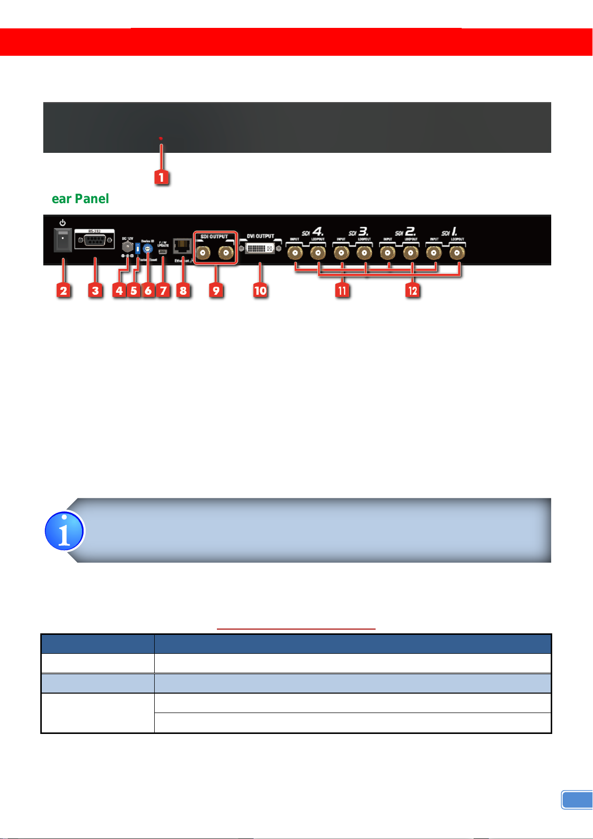
Front Panel
Input Connector
Video Source
DVI-x [x = 1~4]
[1] SDI: SD/HD/3G
Output Connector
Display
DVI-I OUT
[1] DVI display
[2] SDI*2 display
*Default: Turn on the MX-3004 then switch the circled DIP switch simultaneously up and down to
factory default mode.
*These IO ports support various resolutions from 480i up to 1920x1080p, for more details of the
supported modes, please refer to the Appendix – Supported Resolution.
5. Factory Reset
F/W Default
6. Device ID
7. USB
8. Ethernet
9. SDI output
10. DVI output
11. SDI input
12. SDI local loop out
Rear Panel
1. Power Indicator
2. Power On/Off
3. RS-232
4. +12V DC
PANEL DESCRIPTIONS
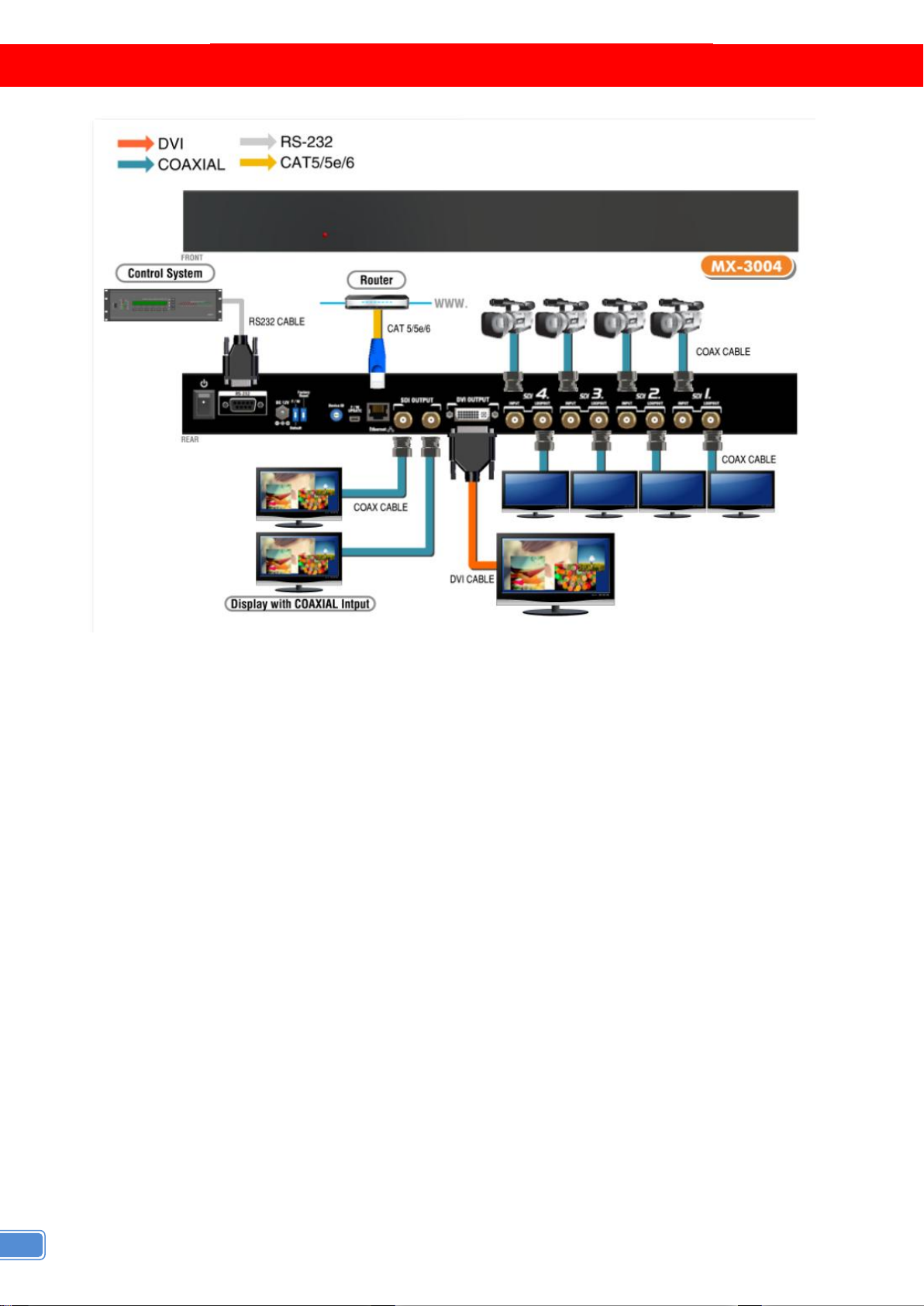
The MX-3004 has 4 SDI and user can display four of them simultaneously on the same screen.
Figure 2 shows the rear panel connectors of a MX-3004 and Table 1 illustrates how you can connect
video devices and display to the MX-3004.
ABLE 1:
T
I/O C
ONNECTORS
4
APPLICATION DIAGRA

5
HARDWARE INSTALLATION
Safety Precautions
1. To prevent fire or shock hazards, do not expose this device to rain or moisture.
2. The product should be placed more than one foot away from heat sources such as radiators, heat
registers, stoves, and other products (including amplifiers) that produce heat. In addition, do not cover
any material or devices on the top of the device.
3. Do not use immediately after moving from a low temperature to high temperature, as this causes
condensation.
4. Do not place this product on an unstable cart, stand, or table. The product may fall, causing serious
injury to a child or adult and serious damage to the product.
5. Unplug this product from the wall outlet before cleaning. Do not use liquid cleaners or aerosol cleaners.
Use a damp cloth for cleaning.
6. Do not allow the same still picture to be projected for a long time or an abnormally bright video picture
to be projected. The video image could be burned in to the display device.
Installation Procedures
Unpacking
Remove the MX-3004 from the shipping container and examine it for any signs of shipping damage
or missing items (check with package contents above). All shipping items should be saved if the product
is to be moved or returned for service. Shipping unit back to dealers for service not in the original box
may result in voiding warranty or additional cost.
Placement
The unit uses convection to cool. A fan is not needed, so do not block the sides of this device or
stack another device on the top or bottom of the MX-3004.
Connections
We recommend the highest quality cables for both input and output connections.
1. Switch off the MX-3004 and all devices that you want to connect.
2. Connect a monitor, a projector or other displays that comes with DVI / SDI inputs
3. Connect a device equipped with SDI output including SD/HD/3G to the BNC input connector of
MX-3004.
4. Connect a device equipped with composite video output to the BNC input connector of the MX-3004.
5. Connect your computer with the MX-3004 by a 9-pin RS-232 cable and then install the software.
6. Plug in AD power cord into AC power socket.
7. Execute the control software and establish the connection between PC/Laptop and MX-3004.
8. For detailed software control operation, please refer to the software instruction section.

6
OPERATION SOFTWARE
System Requirement and Precautions
1. The device provides a software control program, Quartet, which runs under Microsoft Windows 98,
2000, XP, Vista, 7 through the interface of RS-232 serial control.
2. Before you click the icon of the software, make sure you have secured the connection between your
computer COM port and the device and switched on the device with green LED light.
Support Software: V1.4 2014 – 02 – 18
Support Firmware: V1.7 2014 – 02 – 18
Start the Operation Software
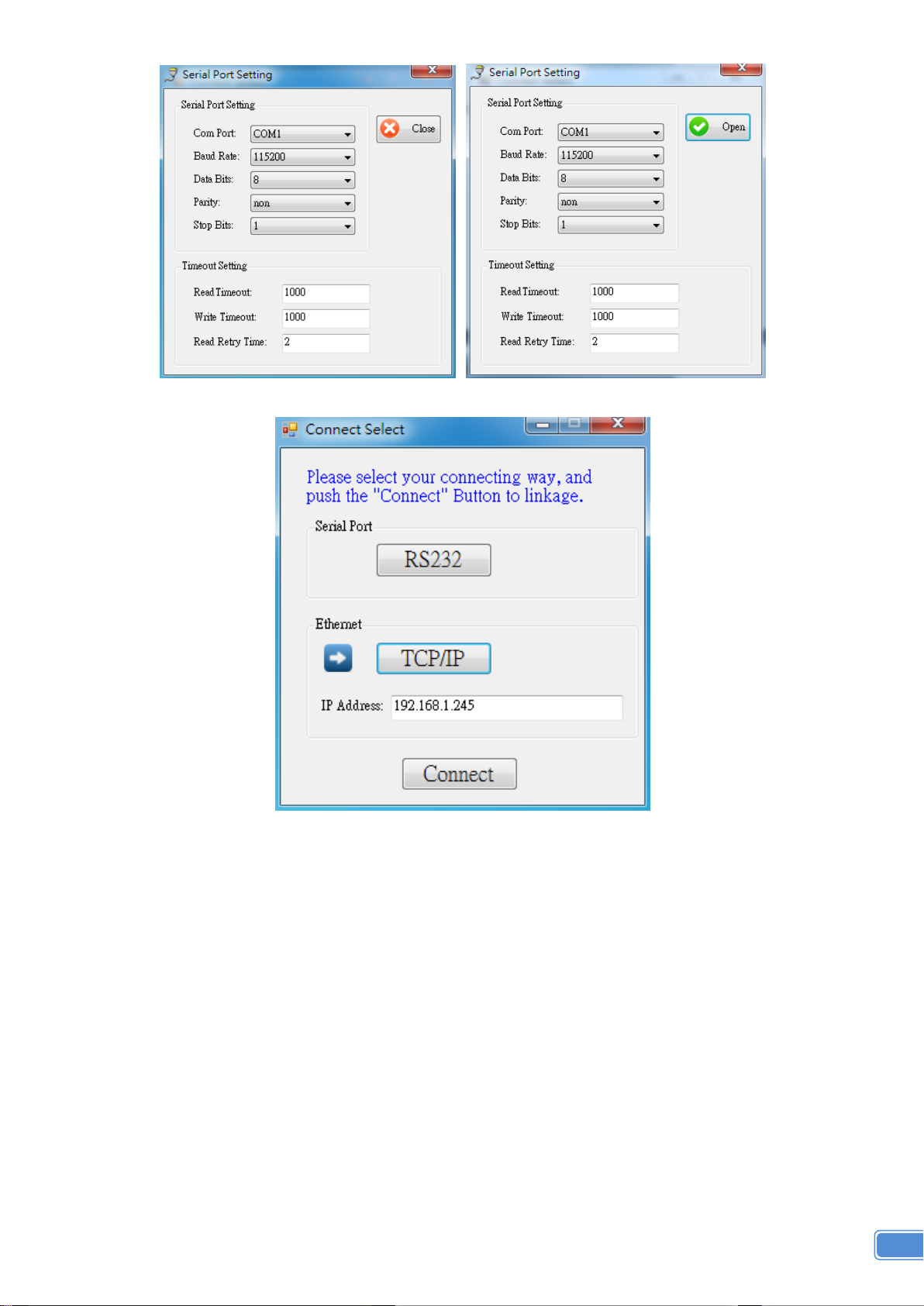
When you click the .exe file, the below dialog will pop-up. You can use two ways to control device RS232
and TCP/IP (under Microsoft Windows 7, please setting this program as an administrator).
RS232 Mode: Push “RS232” button, the below dialog will pop-up. Select correct Com port. Click the
button to open the “Com Port” like right picture, then closing the dialog. If your setting is correct and the
device is ready. It will enter directly to control dialog.
7
TCP/IP Mode: Enter the device IP address and click the “Connect” Button. (How to set the IP address,
please refer the part “TCPConfig” of “Tool Bar List”).
After you select the connecting way to connect the device, it will be pop-up the window as below.

8
Instruction of Software Connection (connect with RS232)
1. PAP Panel: Display and adjust the window size and position.
2. Tool Bar List:
(1) : Get all information of the device and update this software state.
(2) Port setting: Pop-up the “Connect Select” dialog, user can select the connecting way.
(3) : TCP configure setting, we are recommend you to set with RS232.

9
(4) : Click this button, it will be pop-up the “Border Setting” management interface.
Window drop-down list: Setting for window 1~4.
Window Setting
Border Color: Change the border color of window which you want.
Border: Display the border or not.
Window Text: Display the window text or not.
Input Text: Display the input text or not.
Window Text: Reveal the windows text which you are setting in the custom text.
Input Text: Reveal the input text which you are setting in the input custom text.
Custom Text (Max 20): To set up the window text which you want to reveal in the window.
Please take a closer look at the length of string (Max 20).
Border Blink Color: Change the color of the window border which you want to blink.
Blink Time: Setting the blink time of border blink.
Blink Cycle: Setting the blink cycle of border blink. If you want to stop the border blink, you
can click the stop button.
Background Picture: To set up the background picture of window.
Input Custom Text Setting: Setting the input text which you want to show in the window.
Please take a closer look at the length of string (Max 20).
(5) : Pop-up the “Save Custom Mode” dialog.

10
User can adjust the window size and position, and basing on the user setting, they can save the
different PAP mode in custom layout.
(6) Crop Function: Pop-up the “Crop Video” dialog
Picture Box: It is preview the range and effect of video crop with the adjustment.
Window Channel: Choose the window to crop the video.
Crop Enable: Enable crop function
Array Enable: Enable array parameter.
Percent Enable: Enable percent parameter.
Pixel Enable: Enable pixel parameter
Array Tab:

11
Horizontal Array Total = 3
Horizontal Array Start = 1
Horizontal Array End = 2
Vertical Array Total = 3
Vertical Array Start = 1
Vertical Array End = 2
Percent Tab:

12
Pixel Tab:
“Pixel” and “Percent” crop are almost same. It is different from modify value.
(7) : Version, click this button to show version information.
3. Output Resolution: Set the output resolution. When set the different resolution, the parameters of PAP
and custom layout (position and size) will change.

13
4. Control Bar: For PAP Panel Setting.
(1) Control Percent: 10~100% to set the PAP Panel display/control size.
(2) : Pop-Up the “PAP Layout Display” Dialog
(3) : Fix the size ratio when the window is resizing.
5. PAP Mode Control / Input Selection
(1) Major Window: The major window for set the visible, position, size, polarity and
default layout.
(2) Input Selection: Set the window image is which input signal.
(3) Window Polarity: Set the major window layer polarity in “PAP Mode”.
(4) Window Visible: Set the window visible in “PAP Mode”.
(5) Window Position and Size: Set the window position and size in “PAP
Mode”.
6. Full Screen / PAP Mode
(1) Full Screen: Set the major window to full Screen.
Set Window 1 Full Screen
Set Window 2 Full Screen
Set Window 3 Full Screen
Set Window 4 Full Screen

14
(2) PAP Mode: Set to last PAP layout.
Default Layout: Set the default position and size with icon
picture. The “major window” will be the largest size in the icon.
Custom Layout: ……… Set the custom layout by customize saving with
“Tool Bar List” .
Instruction of Software Connection (connect with TCP/IP)
Please take a closer look at the TCP/IP connection. After setting, user should reboot the device, or it will
connect failed.
If the connect of TCP/IP is succeed, it will pop-up the window as below.
Group Control
Action: The checked devices will action when you click the button in the “Group Action Control”
State: The device is under control or not.
“Port” or “Port Num / IP Address”:
You can click to set the “RS232” and “TCP” and it will display the state.
Link: Retry to link the device, When the device isn’t on control.
15
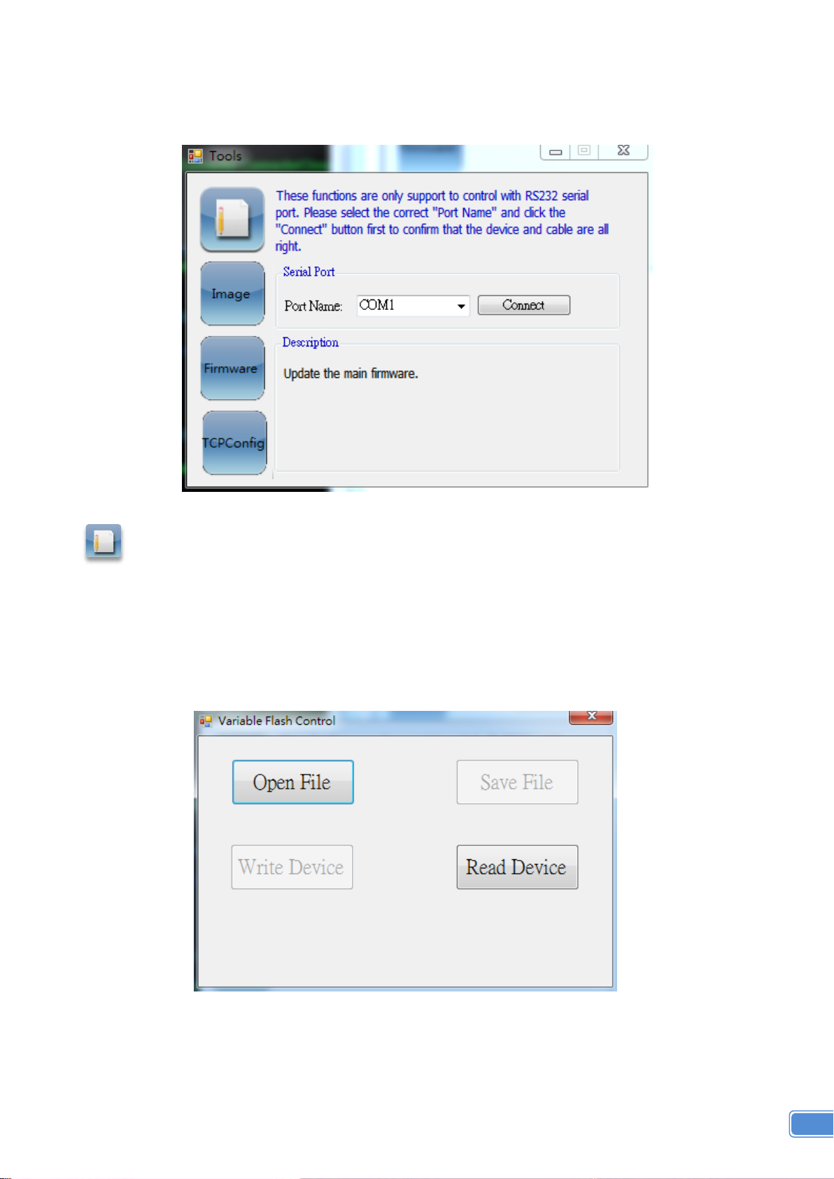
Tool
It is especially different between connect with RS232 and TCP/IP.
Using TCP/IP connecting way, the function is limit to set up the flash setting, image update and firmware
update. But the other function user can follow the instruction manual of the RS232
: Device flash Setting, it will pop-up the “Variable Flash Control” dialog.
Step 1: user can click the “Read Device” button to read this device information
Step 2: Save the device information to bin file.
Step 3: If user have other device want to set the same mode, they can click the ”Open File”
button to open the bin file.
Step 4: Write the bin file to other device.

16
: Image updating, it shall be pop-up the “Image Update” dialog. User can set up the image
information for this device.
Splash Screen: change the startup screen for the software.
Font Data: To set up the display font.
Background Image: User can install the picture into the device.
: Firmware update, click this button, it shall be pop-up the “Firmware update” dialog. User can
select this to update the firmware of the device.
17
TROUBLE SHOOTING
Problem
Recommendations
No power
Check if you correctly and firmly plug AC power core into MX-3004
If you are recovering from power outage, accidentally unplug the power
core or other power surge conditions, leave the device off for a while and
then power it on again.
No/ Erratic video
Make sure all cables are in good working condition and properly
connected to the MX-3004 and displays.
Configure the output video resolution so that it doesn’t excess the native
resolution of the display. ( in this case, the message of “out of range” is
usually showed on your screen)
Make sure video sources are accurately selected to the right channels.
Poor quality
We suggest that don’t use T-connectors to split your video source into to
images displayed on two different screens. That will lower output video
quality. Use a distribution amplifier instead of T-connectors.
Make sure the video source is not compressed and maintains the highest
native resolution.
Wrong color
Use color balance or auto configuration .

18
LIMITED WARRANTY
The SELLER warrants the MX-3004 3G/HD/SD-SDI Quad-view Video Processor to be free from
defects in the material and workmanship for 1 year from the date of purchase from the SELLER or an
authorized dealer. Should this product fail to be in good working order within 1 year warranty period, The
SELLER, at its option, repair or replace the unit, provided that the unit has not been subjected to accident,
disaster, abuse or any unauthorized modifications including static discharge and power surges.
Unit that fails under conditions other than those covered will be repaired at the current price of parts
and labor in effect at the time of repair. Such repairs are warranted for 90 days from the day of reshipment
to the BUYER. If the unit is delivered by mail, customers agree to insure the unit or assume the risk of loss
or damage in transit. Under no circumstances will a unit be accepted without a return authorization
number.
The warranty is in lieu of all other warranties expressed or implied, including without limitations, any
other implied warranty or fitness or merchantability for any particular purpose, all of which are expressly
disclaimed.
Proof of sale may be required in order to claim warranty. Customers outside Taiwan are responsible
for shipping charges to and from the SELLER. Cables are limited to a 30 day warranty and cable must be
free from any markings, scratches, and neatly coiled.
The content of this manual has been carefully checked and is believed to be accurate. However, The
SELLER assumes no responsibility for any inaccuracies that may be contained in this manual. The
SELLER will NOT be liable for direct, indirect, incidental, special, or consequential damages resulting
from any defect or omission in this manual, even if advised of the possibility of such damages. Also, the
technical information contained herein regarding the MX-3004 features and specifications is
subject to change without further notice.
 Loading...