

Page 1
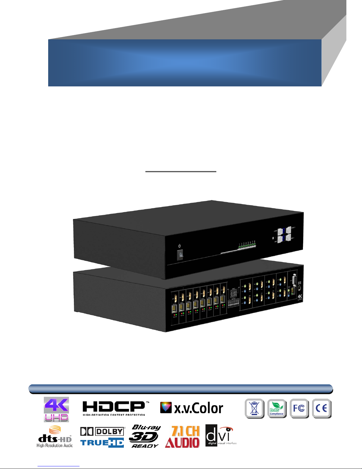
8X8 HDBaseT Lite Matrix with PoC,
HDCP2.2 & 4K2K60 (YUV420)
User Manual
rev: 151209
Made in Taiwan
M
M
A
A--
5
5
4
4
8
8
8
8
V
V
2
2
Page 2
Safety and Notice
The MA-5488V2 8x8 HDBaseT Lite matrix with PoC, HDCP2.2 & 4K2K60 (YUV420) has been
tested for conformance to safety regulations and requirements, and has been certified for
international use. However, like all electronic equipments, the MA-5488V2 should be used with care.
Please read and follow the safety instructions to protect yourself from possible injury and to minimize
the risk of damage to the unit.
● Follow all instructions and warnings marked on this unit.
● Do not attempt to service this unit yourself, except where explained in this manual.
● Provide proper ventilation and air circulation and do not use near water.
● Keep objects that might damage the device and assure that the placement of this unit is on a
stable surface.
● Use only the power adapter and power cords and connection cables designed for this unit.
● Do not use liquid or aerosol cleaners to clean this unit. Always unplug the power to the device
before cleaning.
TABLE OF CONTENTS
INTRODUCTION................................................................................................................. 1
FEATURES ......................................................................................................................... 1
ACKAGE CONTENTS ........................................................................................................ 1
SPECIFICATIONS .............................................................................................................. 2
PANEL DESCRIPTIONS ..................................................................................................... 3
Transmitting unit ► MA-5488V2 .............................................................................. 3
Receiving unit ► CV-745V ...................................................................................... 4
IR PASS-THROUGH ........................................................................................................... 5
CONNECTION DIAGRAM .................................................................................................. 6
OPERATION APPROACH .................................................................................................. 7
EDID LEARNING .............................................................................................................. 19
FAQ .................................................................................................................................. 20
NOTICE ............................................................................................................................ 21
WARRANTY ..................................................................................................................... 22
Page 3

INTRODUCTION
The MA-5488V2 8x8 HDBaseT Lite matrix with PoC, HDCP2.2 & 4K2K60 (YUV420) provides the most
flexible and cost effective solution in the market to route high definition video sources plus multi-channel
(up to 7.1-channel) digital audio from any of the eight HDMI sources to the remote displays at the same
time. Through only one low cost Cat-5/5e/6 LAN cables, not only high quality video and audio can be
transmitted to the display sites, but also users can switch among eight HDMI sources using the push
button, remote control or IP control. Furthermore, the built-in IR extension function makes users at display
site access the DVD player, PS3 or any HDMI supported devices directly! In addition, MA-5488V2 also
supports PoC (Power over Cable) which can power both units from TX with power supply.
FEATURES
● Supports HDMI Deep Color, full 3D, 4K2K@60Hz (YUV 4:2:0)
● Extends the HDMI transmission up to 70m (230ft) from the HDMI source at Full HD 1080p 48-bit, and
40m (130ft) at 4K2K@60Hz (YUV 4:2:0)
● Supports PoC(Power over Cable) which can power both units from TX side with power supply
● HDCP1.4 & HDCP2.2 compliant
● Bi-directional IR pass-though
● Allows controlling local HDMI sources or display through control pat h
● Allows controlling matrix switcher from IR re mote
● Pure unaltered uncompressed 7.1ch digital HDMI over Cat.5/5e/6 cable transmission
● Allows any source to be displayed on multiple displays at the same time
● Allows any HDMI display to view any HDMI source at any time
● Supports 7.1 channel digital audio
● Supports default HDMI EDID and learns the EDID of displays to matrix switcher
● The matrix switcher can switch every output channels from any HDMI inputs by Push button, IR remote
control, RS-232, IP control and web-interface control
● Easy installation with rack-mounting
● Fast response time – 2~4 seconds for channel switch
ACKAGE CONTENTS
● 1x MA-5488V2 ● 1x DC 24V 8.3A
● 9x IR receiver ● 8x IR blaster*
● 1x Rack-mounting ear set ● 1x IR Remote control*
● 1x Installation software CD ● 1x User Manual
* Additional IR remote controllers and IR blasters can be purchased as optional accessories to
control the HDMI sources located separately.
1
Page 4

SPECIFICATIONS
Model Name
MA-5488V2
Technical MA-5488V2
CV-745V
Role of usage
True 8x8 matrix switcher
Transmitter [TX]
Receiver [RX]
HDMI compliance
HDMI Deep Color, full 3D & 4K2K@60Hz (YUV 4:2:0)
HDCP compliance
Yes
Video bandwidth
Single-link 340MHz [10.2Gbps]
Video support 480i / 480p / 720p / 1080i / 1080p60 / 4K2K@60Hz (YUV 4:2:0)
Audio support Surround sound (up to 7.1ch) or stereo digital audio
PoC support
YES
HDMI over UTP
transmission range
1080p@60 – up to 70m (230ft) [CAT.X]
4K2K@60(YUV 4:2:0) – 40m (130ft)
Input TMDS signal
1.2 Volts [peak-to-peak]
Input DDC signal
5 Volts [peak-to-peak, TTL]
ESD protection
[1] Human body model — ±19kV [air-gap discharge] & ±12kV [contact discharge]
PCB stack-up 4-layer board [impedance control — differential 100Ω; single 50Ω]
Input
8x HDMI / 1x RS-232 / 1x RJ-45 for IP
Control / 9x IR socket for IR receiver
1x RJ-45(HDBaseT) /
1x IR socket for IR receiver
Output
8x RJ-45(HDBaseT) / 8x HDMI /
9x IR socket for IR blaster
1x HDMI /
1x IR socket for IR blaster
HDMI Input selection
Push button / IR remote control / RS-232
control / IP control
IR remote cont rol
HDMI source control
Controllable via IR pass-through from IR receiver at RX to IR blaster at TX
IR remote cont rol
Electro-optical characteristics: π = 25° / Carrier frequency: 30-56kHz
HDMI connector
Type A [19-pin female]
RJ-45 connector
WE/SS 8P8C
RS-232 connector
DE-9 [9-pin D-sub female]
N/A
3.5mm connector
Earphone jack for IR blaster
[All IR Out]
IR signal from all outputs
[IR1~IR8]
IR control on individual source
device
Earphone jack for IR receiver
[System IR]
Receives IR commands
from remote control
[IR1~IR8]
Receives IR commands from
individual remote control
Earphone jack for IR blaster
[IR]
IR control on individual display device
Earphone jack for IR receiver
[IR]
Receives IR commands from remote
control
Mechanical MA-5488V2
CV-745V
Enclosure
Metal case
Dimensions
(L x W x H)
Model
438 x 319 x 100mm [3.9" x 3.5" x 1 "]
100 x 89 x 26mm [3.9" x 3.5" x 1 "]
Package
425 x 612 x 235 mm [1'4" x 2' x 9.2"]
Carton
626 x 439 x 260 mm [2'1" x 1'4" x 10.2"]
Weight
Model
4600g [19 lbs]
TBA
Package
8.7kg [10 lbs]
Fixedness
2RU rack-mount with ears
Wall hanging holes
Wall-mount with screws
Power supply 24V 8.3A DC
None
Power consumption
120 Watts [max]
None
Operation temperature
0~40°C [32~104°F]
Storage temperature
-20~60°C [-4~140°F]
Relative humidity
20~90% RH [no condensation]
2
Page 5
PANEL DESCRIPTIONS
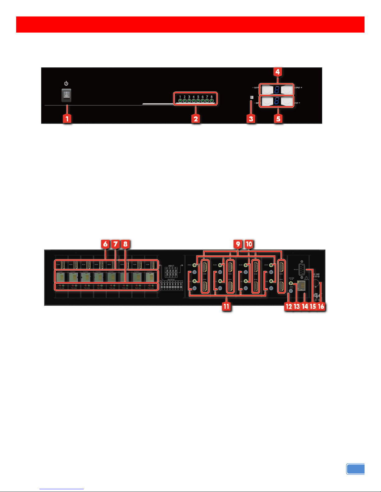
Transmitting unit ► MA-5488V2
Front Panel
1. Power Switch
2. Source Status: Input source indicator LED
3. IR SENSO R: IR sensor for receiving the IR commands from IR remote
4. Output Push Button & 7-segment LED: Front panel push buttons used to select the number of
display channel & LED display for output ports
5. Input Push Button & 7-segment LED: Front panel push buttons used to select the number of input
source & LED display for input channels
Rear Panel
6. HDMI Local Loopout Port 1-8: Local loopout HDMI outputs for each output channel
7. RJ-45: HDBT output port 1-8
8. LED: Link/ PoC indicator
9. IR Receiver 1-8: Infrared 3.5mm socket for plugging in the extension cable of IR receiver
10. INPUT 1-8: HDMI inputs
11. IR Blaster 1-8: 3.5mm IR blaster socket for individual HDMI source control
12. All IR Output: 3.5mm IR blaster socket for HDMI source control on all 8 inputs
13. System IR Receiver: Ext. IR receive
14. Ethernet: Ethernet control port
15. RS-232: RS-232 control port
16. +24V DC: 24V DC power jack
3
Page 6
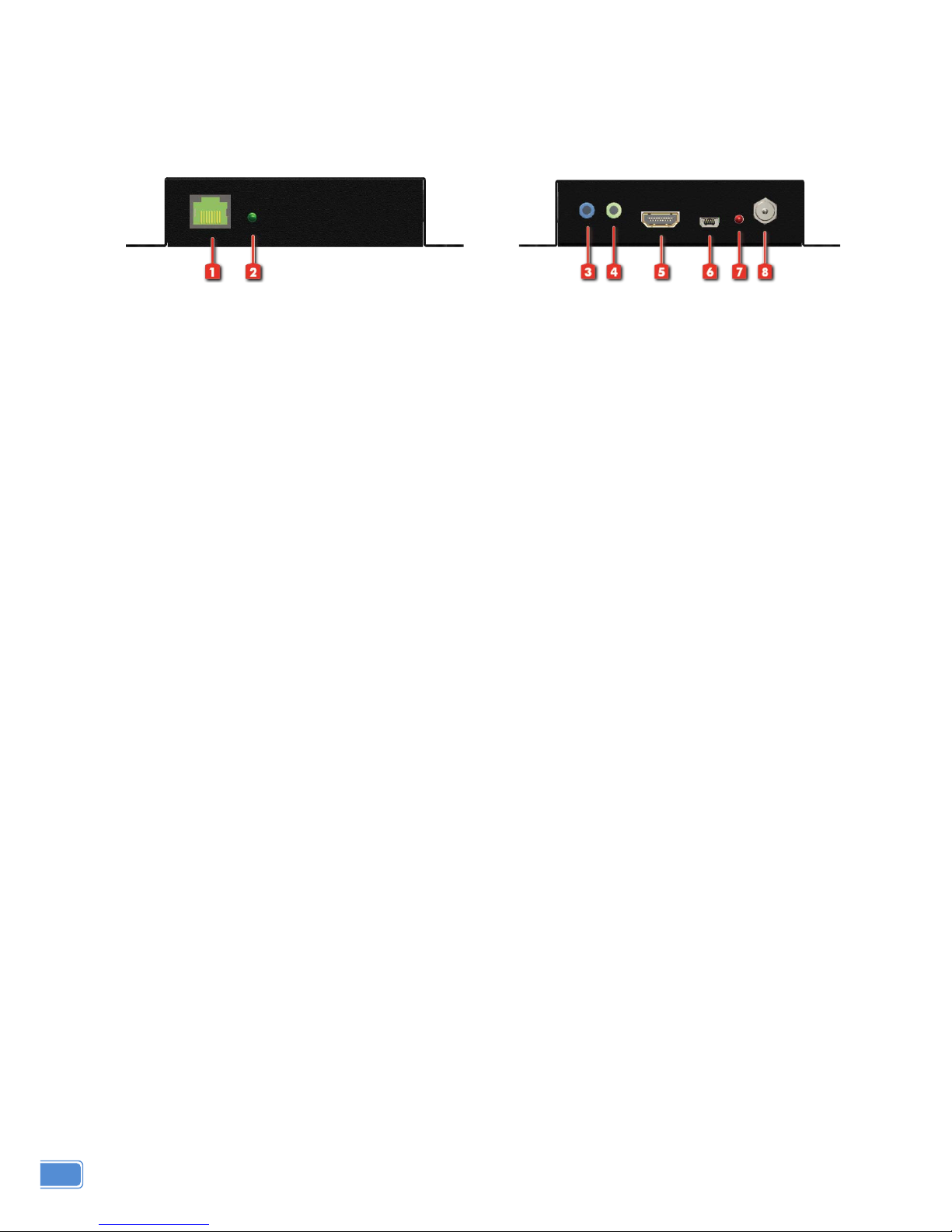
Receiving unit
►
CV-745V
Front Panel
Rear Panel
1. RJ-45: Plug in a Cat.X cable
2. LED: Link indicator
3. IR Bla ste r : Infr ar ed 3.5mm socket for plugging in the extension cable of IR blaster
4. IR Receiver: Infrared 3.5mm socket for plugging in the extension cable of IR receiver
5. HDMI Output: Connect to HDTV with a HDMI cable
6. Mini-USB: F/W update
7. LED: Power indicator
8. +24V DC: Doesn’t require power here
4
Page 7
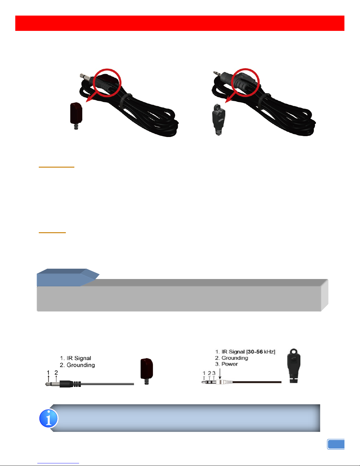
IR PASS-THROUGH
IR Extenders
IR Blaster
IR Receiver
IR Sockets
MA-5488V2
All IR Out: The default location for IR blaster to transmit all IR command signals received from any of the
four remote receivers to all of the HDMI sources.
IR BLASTER 1-8: IR blaster connected here can only transmit IR command signals from the remote
receivers that are setting at respective input channel from 1 to 8.
System IR: Receives IR commands from remote control
IR RECEIVER 1-8: Receives IR commands from individual remote control
CV-745V
IR BLASTER: IR control on individual display device
IR RECEIVER: IR receiver connected here can receive all IR command signals from the IR remote
controls of MA-5488V2 and all other HDMI source devices.
Definition of IR Earphone Jack
IR Blaster IR Receiver
You can buy any IR extension cables in the market that are compatible to the definition of
the IR sockets for the matrix if necessary for replacement use. However, IR cables longer
than 2m (6-ft) may not work.
Incorrect placement of IR Blaster and Receiver may result in the failure of the IR extenders. Please check
carefully before plugging in the IR extender to the respective IR sockets. Warranty will not cover the damage.
CAUTION!
5
Page 8
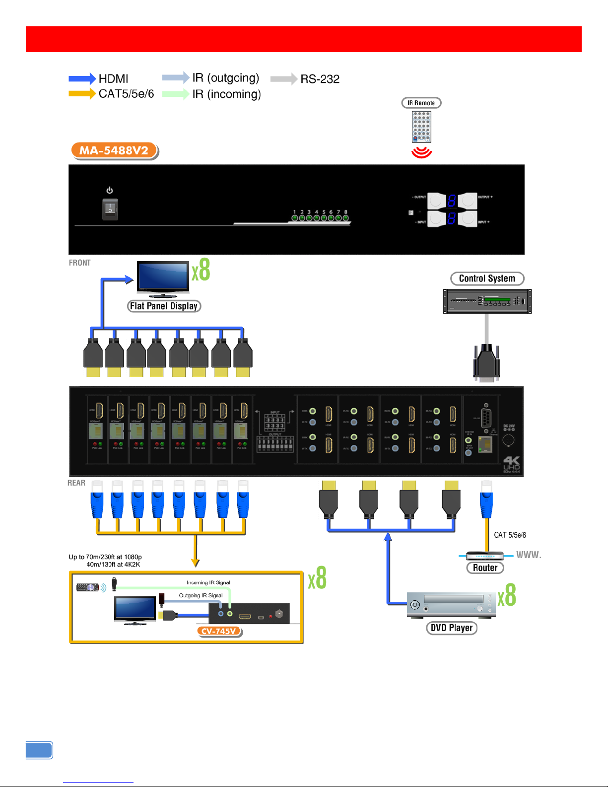
CONNECTION DIAGRAM
6
Page 9
OPERATION APPROACH
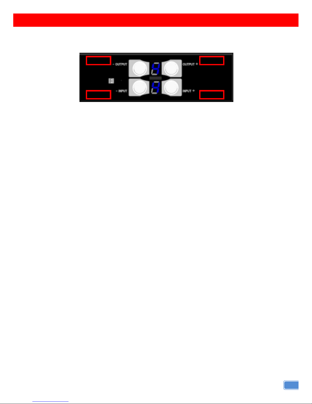
Method A: Push-in Button
1. IN/OUT MAP
1) Use the “+”or “-“ output push button to select the number of display
2) Use the “+”or “-“ input push button to select the number of input source
“+”: change selected input/output port in ascending order
“-” : change selected input/output port in descending order
After you select the desired input/output port, the LED will blink twice and the setting will be effective
2. Save Mapping Mode
1) Keep pushing “output+ (save)”button until the output LED shows “d.” to enter the Save Mapping
Mode.
2) Use the “+”or “-“ input push button to select the mapping configuration (1~8) which you want to save
current input/output mapping
3) After you select the desired mapping con figuration number, the LED will blink twice and the mappin g
setting will be saved
4) If you push the “output- (preset)”button before the mapping setting is saved, the LED will show
“一”“一”to quit the Save Mapping Mode
3. Preset Mapping Mode
1) Keep pushing “output- (preset)” button until the output LED shows “P.” to enter the Preset Mapping
Mode.
2) Use the “+”or “-“ input push button to select the saved mapping configuration (1~8) which you want
to recall
3) After you select the desired mapping configuration number, the LED will blink twice and the mapping
setting will be effective
4) If you push the “output+ (save)”button before the mapping setting is effective, the LED will show
“一”“一”to quit the Preset Mapping Mode
default
learn
preset
save
7
Page 10

4. Default EDID Mode
1) Push “input+(default)” button to select the input channel which you want to learn default EDID and
then keep pushing “input+(default)”button when you select your desired input channel
2) Push the “+”or “-” output push button and then the LED will show “E”“d” one time to enter Learn
Default EDID Mode
3) Use “+”or “-” output push button to select the default EDID mode(1~8)
4) Release “input+(default)”button after selecting the desired default EDID mode, and then the LED will
blink twice and the setting will be effective
5) It will quit the Learn Default EDID Mode if you push the “input- (learn)”button before the setting is
effective
6) T he LED will show “0”“0” if the setting is success
The LED will show “F”“F” if the setting is failure
5. EDID Learning Mode
1) Connect display to input 8(EDID port for learning EDID from display).
2) Push “input- (learn)”button to select the input channel which you want to learn EDID from EDID Port
and then keep pushing “input- (learn)”button when you select your desired input channel
3) Push the “+”or “-” output push button and then the LED will show “E”“Number” to enter Learn Output
EDID Mode.
Ex: Learn EDID Port to Input 2
The LED will show “E””2”
4) Release “input- ( lear n)”butt on, and then the LED will blink twice and the setting will be effective
5) It will quit the Learn Output EDID Mode if you push the “input+ (default)”button before the setting is
effective
6) T he LED will show “0”“0” if the setting is success
The LED will show “F”“F” if the setting is failure
8
Page 11
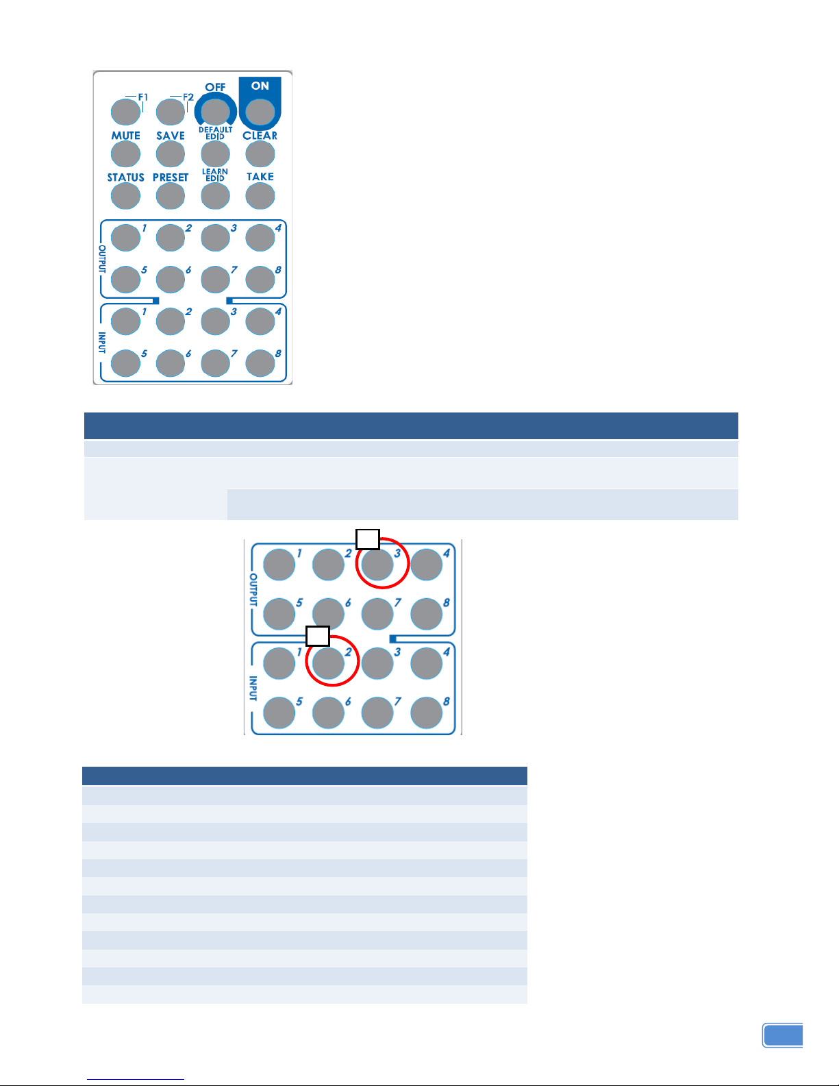
Method B: IR Remote Control
1. IN/OUT Switch
Operation Procedure 7-Segment LED
IN/OUT Switch
Output Number (1~8) + Input Number (1~8)
Ex: Input 2
To Output 3
1. Press output number key “3” to select Output 3
3
-
2. Press input number key “2” to select Input 2
3
2
2. Function Key
Button
Function
OFF
Standby mode
ON
Power on the matrix switcher
MUTE
Turn off output’s video and audio
STATUS
Preset output status
SAVE
Save current mapping mode
PRESET
Preset mapping mode
DEFAULT EDID
Begin default EDID selection
LEARN EDID
Begin EDID learning from one output
CLEAR
Clear the previous IR operation procedure
TAKE
Trigger the previous setting
F1
Reserved
F2
Reserved
1
2
9
Page 12

Operation Procedure 7-Segment LED
Output Status
Status + Output Number (1~8) + Take
Ex: Output 4
(Input 2)
1.Press “STATUS” button
-
-
2.Press output number key “4” to select Output 4
4
-
3.Press “TAKE” button
4
2
Save Current Mapping
Save + Output Number (1-8 storage site) + Take
Ex: Save current
mapping to 5
1.Press “SAVE” button
d
-
2.Press output number key “5” to select the storage
site 5
d
5
3.Press “TAKE” button
Preset Mapping
Preset + Output Number (1-8 storage site) + Take
Ex: Preset saved
mapping from 5
1.Press “PRESET” button
P
-
2.Press output number key “5” to select the storage
site 5
P
5
3.Press “TAKE” button
Learn default EDID
Default EDID + Output Number (1-8 default EDID) +
Input Number (input 1~8) + Take
Ex: Default EDID 2
Input 3
1.Press “DEFAULT EDID” button
E
d
2.Press output number key “2” to select default EDID 2
2
d
3.Press input number key “3” to select Input 3
2
3
4.Press “TAKE” button
0 F
0 (success) F(fail)
Learn EDID Port EDID
Learn + Output 8 (EDID Port) +Input Number (input
1~8) + Take
Ex: Learn EDID Port
Input 3
1.Press “LEARN” button
E
L
2.Press output number key “8” to select EDID Port
8
L
3. Press input number key “3” to select Input 3
8
3
4.Press “TAKE” button
0 F
0 (success) F(fail)
Mute Output
Mute + Output Number (1~8) + Take
Ex: Mute Output 3
1. Press “MUTE” button
-
0
2. Press output number key “3” to select Output 3
3
0
3.Press “TAKE” button
3
0
10
Page 13
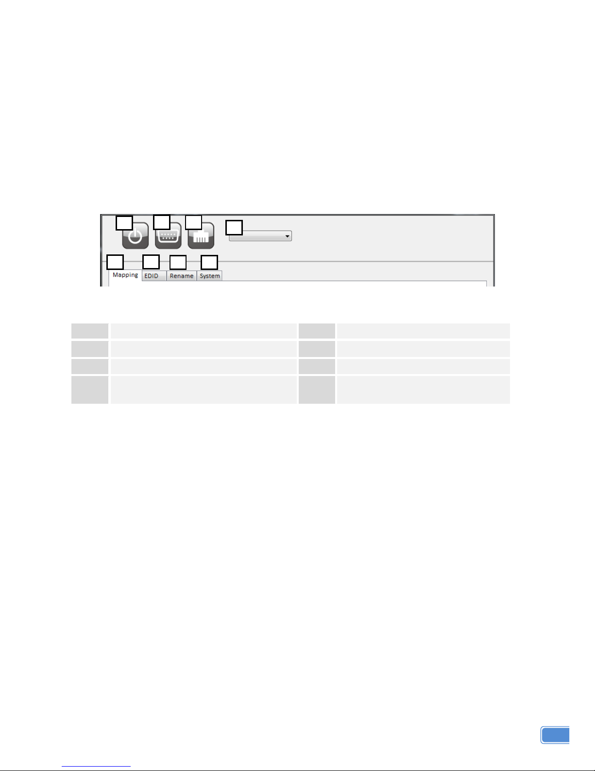
Method C: Software Control through RS-232 port / Ethernet port
1. System Requirement
1) OS Information: MS WinXP/7
2) Baud rates: 9600
3) Software size: 3 MB
4) Minimum RAM requirement: 256 MB
Method D: Software Control through RS-232 port
1
Power ON/ Standby mode
5
I/O Routing Button
2
Control SW via RS-232
6
EDID Button
3
Control SW via Network
7
Rename I/O Button
4
COM Port Selection
8
F/W Update & Default Reset
Button
1 2 3 4 5 7 8
6
11
Page 14
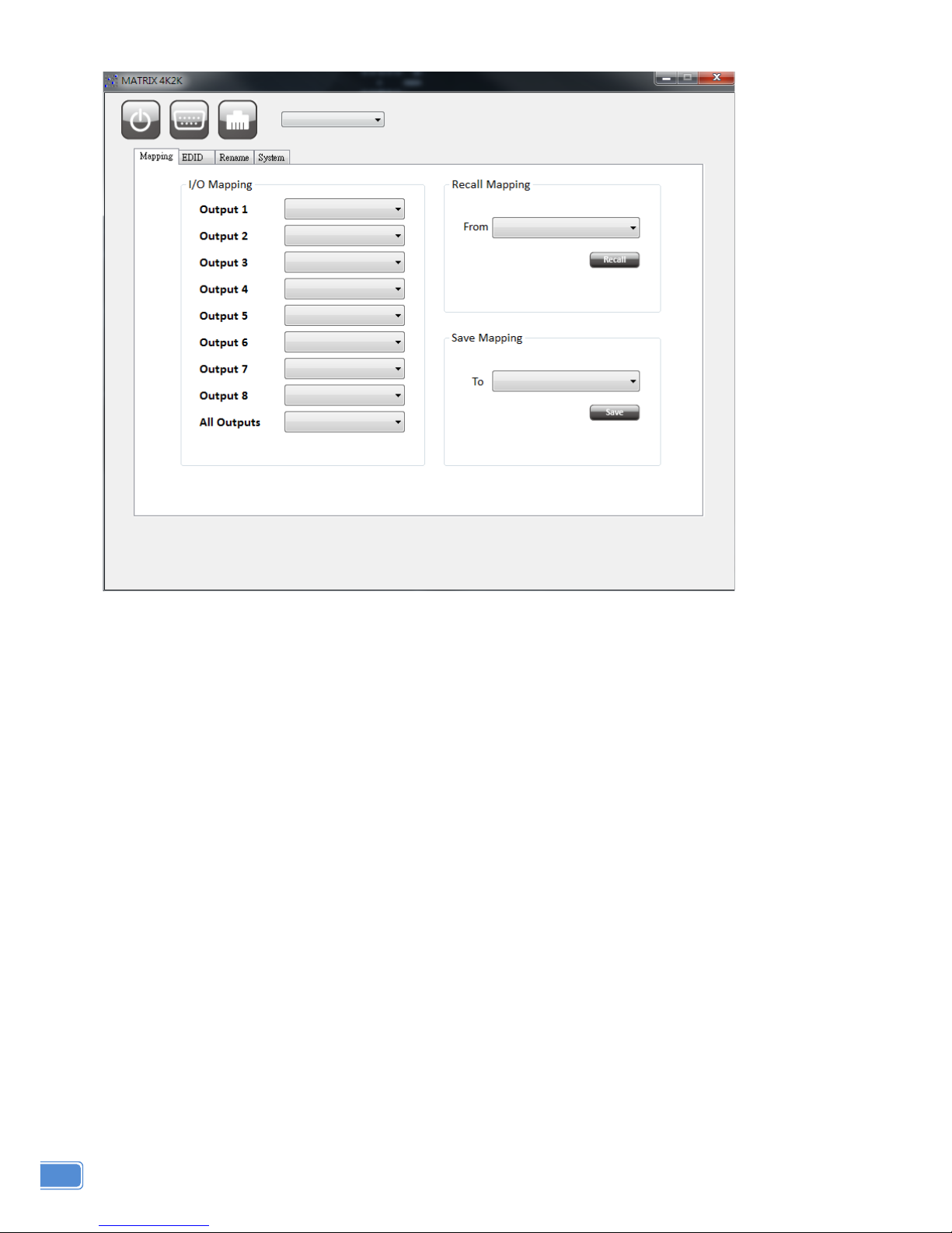
1. I/O Routing Button
1) I/O Mapping:
a) Switch the input for each output
2) Recall Mapping:
a) Select the stored Mapping(1-8)
b) Click “Recall” button to recall previous mapping which are saved
3) Save Mapping:
a) Select Mapping(1-8)
b) Click “Save” button to save current mapping
12
Page 15
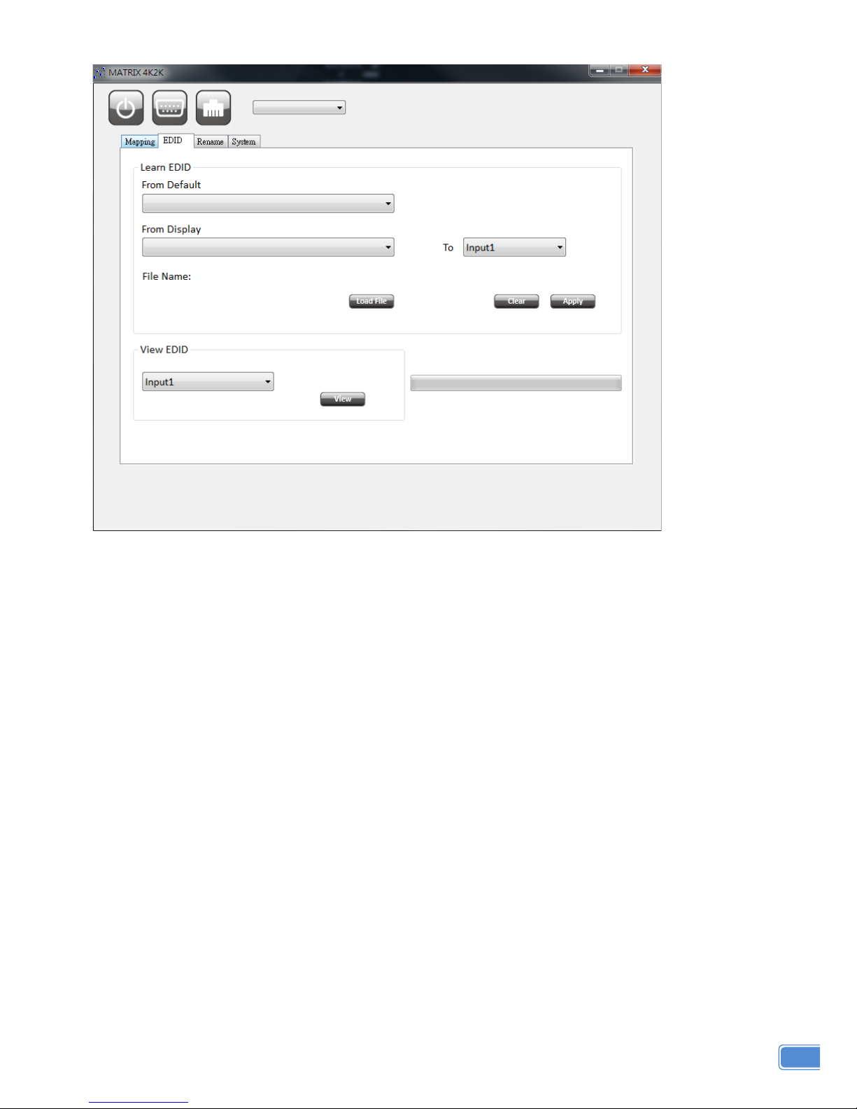
2. EDID Button
1) Learn EDID from Default to Input
a) Select Default EDID(1-11 Default EDID)
b) Select designated Input
c) Click “Apply” button to learn from default EDID
2) Learn EDID from Display to Input
a) Select output
b) Select designated Input
c) Click “Apply” button to learn from display EDID
3) Load EDID File to Input
a) Click “Load File” button to select the EDID file
b) Select designated Input
c) Click “Apply” button to load EDID File
4) View EDID
a) Select Input or HDMI/HDBT output
b) Click “View” button to read and analyze the EDID
13
Page 16
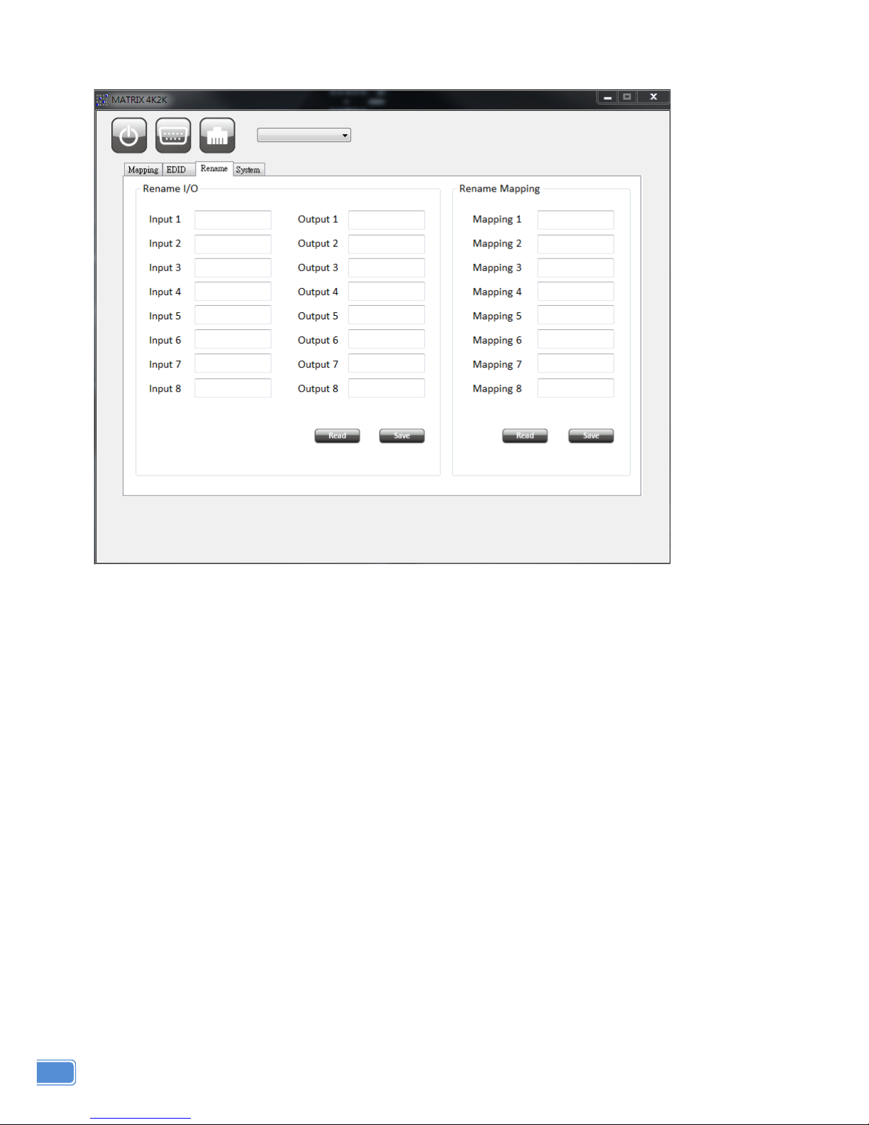
3. Rename I/O Button
1) Rename I/O:
a) Rename the Inputs
b) Rename the Outputs
2) Rename Mapping:
a) Rename the Mappings
14
Page 17
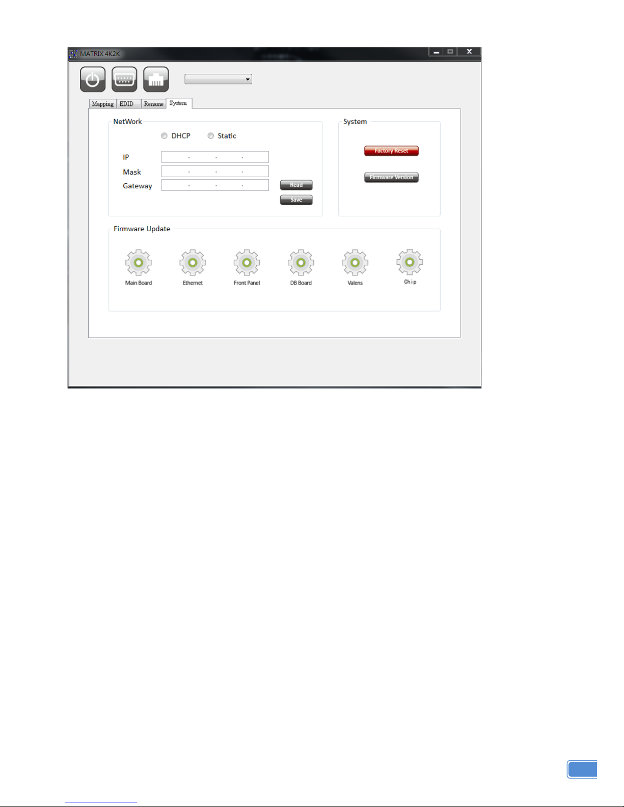
4. System Button
1) Network
a) DHCP mode
=> Click DHCP and then click the “Read” button to get the IP address Info
b) Static mode
=> Click Static and then key in the “IP”, “MASK”, ”GATEWAY” info. After setting IP
Address, please click “Save” to save IP address Info
c) “Save” button
=> Save the key- in IP addr es s
d) “Read” button:
=> Read the IP address from the device
Note: The default IP address is 192.168.1.111
2) System
a) Factory Reset
b) Firmware Version
=> To get the F/W version information
3) Firmware Update
=> Firmware update Main Board/ Ethernet/ Front Panel/ DB Board/ Valens/ Chip
15
Page 18
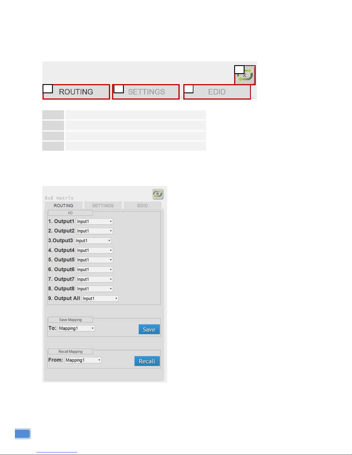
Method E: Web Interface Control
The default IP address:
192.168.1.111
Account:
admin
Password:
matrix
1
I/O Routing Button
2
Setting Button
3
EDID Button
4
Refresh I/O Status & Read I/O Name Button
1. I/O Routing Button
1) I/O:
a) Select the input
2) Save Mapping:
a) Select Mapping(1-8)
b) Click “Save” button to save current
mapping
3) Preset Mapping:
a) Select Mapping(1-8)
a) Click “Recall” button to recall previous saved
mapping
1 2 3
4
16
Page 19
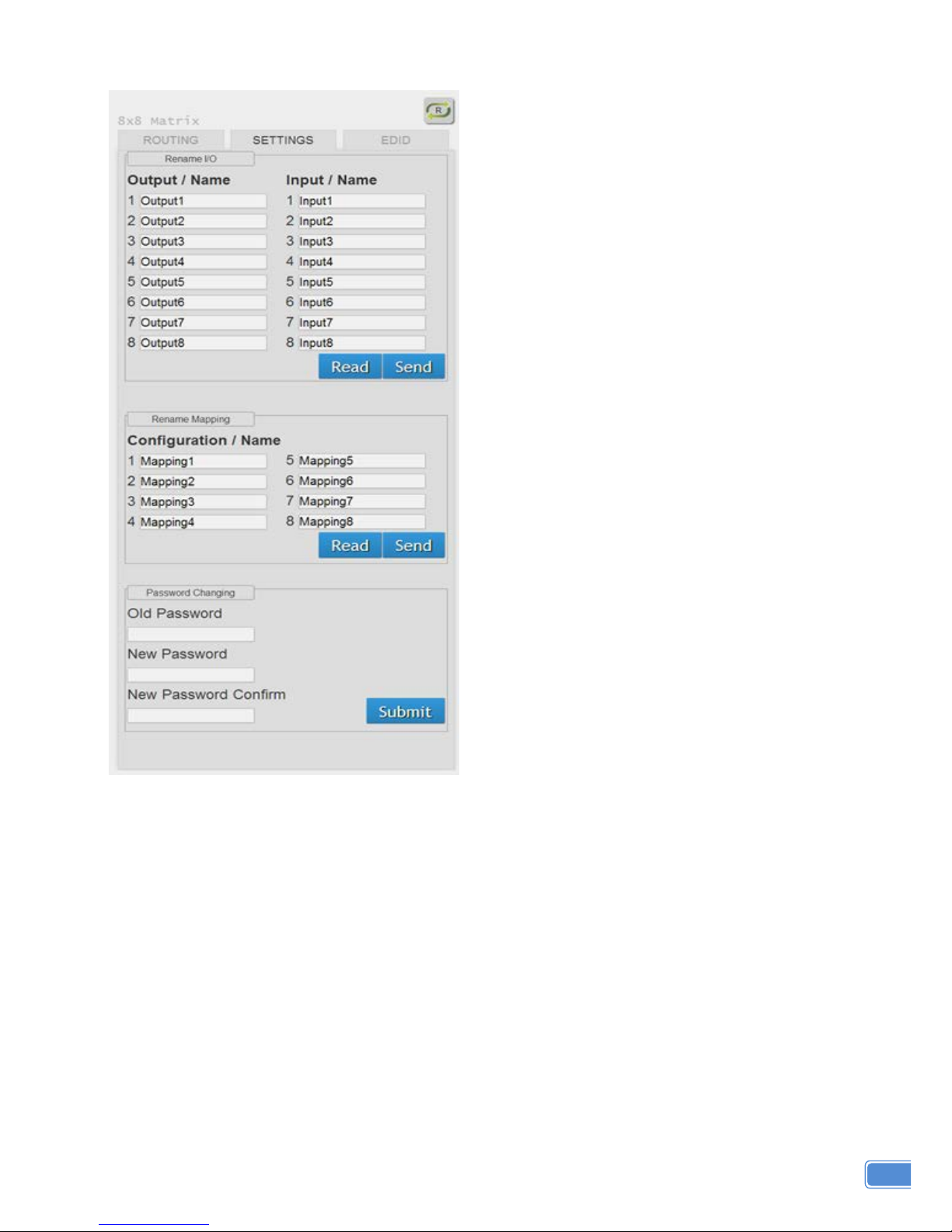
2. Setting Button
1) Rename I/O:
a) Rename output name
b) Rename input name
c) “Read” button: to read I/O name from device
d) “Send” button: to send the chang ed I/O name
to device
2) Rename Mapping:
a) Rename Mapping name
b) “Read” button: t o r e ad m appi ng name from
device
c) “Send” button: to send the changed
mapping name to device
3) Password change: (the password has to be 6
characters)
a) Key in “old password”
b) Key in “new password”
c) Key in “new password” again
17
Page 20
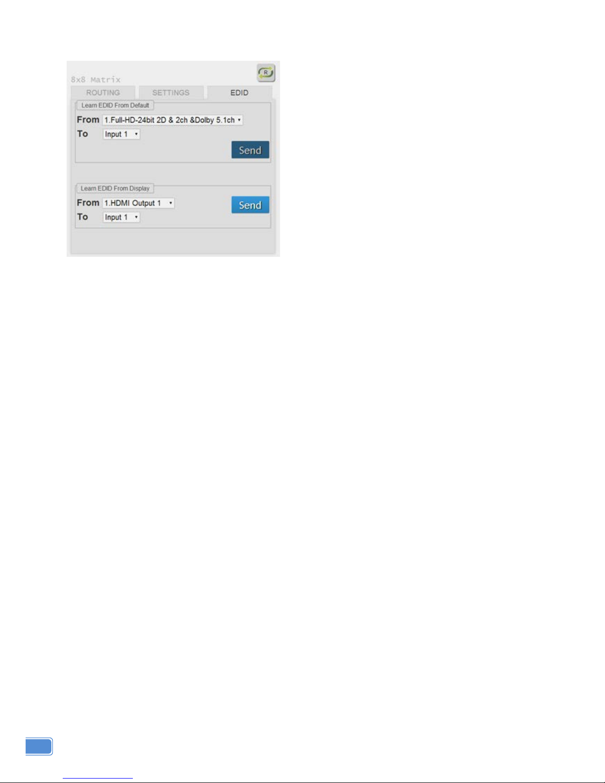
3. EDID Button
1) Learn EDID from Default
a) Select Default EDID(1-11 Default EDID)
b) Select Input
c) Click “Send” button t o learn default EDID
2) Learn EDID From Display
a) Select output
b) Select Input
c) Click “Send” button to learn display EDID
4. Refresh I/O Status Button
18
Page 21

EDID LEARNING
The EDID learning function is to resolve audio and video playing issues at HDMI output port.
Because the HDMI source devices and displays may have various level of capability in playing audio and
video, the general principle is that the source device will output the lowest standards in audio format and
video resolutions to be commonly acceptable among all HDMI displays. In this case, a 720p stereo HDMI
signal output would be probably the safest choice. Nevertheless, the user can force the matrix to learn the
EDID of the lowest capable HDMI display among others to make sure all displays are capable of playin g
the HDMI signals normally.
There are THREE methods to do EDID Learning as below,
1. IR Remote Control: Please refer to the Operation Approach\ Method B: IR Remote Control
2. Software Control: Please refer to the Operation Approach\ Method C: Software Control through
RS-232 port
3. Web Interface Control: Please refer to the Operation Approach\ Method D: Web Interface Control
There are eleven embedded default EDID as below,
1. 4k2k@30-24bit 2D & 2ch
2. 4k2k@30-24bit 2D & 7.1ch
3. Full-HD(1080p@60)-24bit 2D & 2ch
4. Full-HD(1080p@60)-24bit 2D & 7.1ch
5. Full-HD(1080p@60)-24bit 3D & 2ch
6. Full-HD(1080p@60)-24bit 3D & 7.1ch
7. HD(1080i@60)(720p@60)-24bit 2D & 2ch
8. HD(1080i@60)(720p@60)-24bit 2D & 7.1ch
9. Full-HD(1080p@60)-36bit 2D & 2ch [ONLY can be used via SW & Web control]
10. Full-HD(1080p@60)-36bit 2D & 7.1ch [ONLY can be used via SW & Web control]
11. Full-HD(1080p@60)-24bit 2D & 2ch & Dolby 5.1ch [ONLY can be used via SW & Web control]
19
Page 22

FAQ
Q
Can I use any kind of LAN cable?
A
Please check the NOTICE section for more information about how to pick up a suitable cable.
Q
Can every TV work with the HDMI matrix?
A
Basically, the answer is YES. But if your TV can not support 1080p, please refer the EDID
LEARNING section to learn EDID from your TV.
Q
What is EDID? Why do I need to learn EDID?
A
EDID contains the whole information of the display such as the resolution and audio setting which
this display can support. Therefore, based on the EDID information, media player will pick up the
most suitable resolution and audio setting to the display. In order to faithfully transmit the EDID
information from display to the media player, learning EDID from display to this device is
necessary.
Q
What should I do to learn EDID for the matrix?
A
Due to the limitation of HDMI, the source device can only output one format of video and audio. In
other words, the source device cannot output 720p and 1080p video at the same time, or output
stereo and surround sound at the same time. Therefore, you may need to manually setup each
HDMI input for desirable audio/video output format. The mechanism of EDID Learning is to pick up
the HDMI display with the lowest capability among the ones you would use for this input source.
For example, if user would like to play the Input-2 upon output-2, output-3 and output-4, and only
output-3 cannot support 1080p [support up to 720p only], please learn the EDID from the display
connected to the output-3 at the Input-2 port. Of course, if outpt-3 would get the HDMI signals from
every HDMI input, please learn EDID information from output3 to all four HDMI inputs. For more
information about EDID Learning, please refer to EDID LEARNING section.
Q
My TV can support 1080p, but why there is no audio?
A
The factory default EDID of this device is 1080p & 2ch audio. However, there would be a problem
after you change to use 1080p & 7.1ch if the TV cannot support 7.1ch audio. Please use the
default EDID, 1080p & 2ch audio.
Q
When I set an audio amplifier (AV receiver) between TV and the matrix to extract 7.1ch
audio, but why there is still no audio?
A
Basically, the default EDID of the chosen input can support 7.1ch audio, but the problem is that the
EDID of the amplifier still cannot match the default setting. Therefore, the best method is to learn
EDID from the amplifier direct ly. Please refer to EDID LEARNING section and follow the steps to
learn the EDID. When learning EDID from the amplifier, user just needs to connect the matrix and
amplifier. Please don't connect HDMI cable between amplifier and TV when the EDID
learning is proceeding.
Q
When I play the same content upon multi-displays, why only the TV equipped with amplifier
can have 7.1ch audio, and the others don't have 7.1ch audio even no stereo?
A
Due to the limitation of HDMI, the source only can choose one video and one audio format to play,
which can be either 1080p and 7.1ch or 1080p and stereo audio. It means when the user sets the
matrix at 1080p and 7.1ch, the source will only play the content under this format. Therefore if the
TV cannot decode 7.1ch audio, there is definitely no audio.
20
Page 23

NOTICE
1. If the DVI or HDMI device requires the EDID information, please use EDID Reader/Writer to retrieve
and provide DVI/HDMI EDID information.
2. All HDMI over Cat.X transmission distances are measured using Belden 1583A CAT5e 125MHz LAN
cable and ASTRODESIGN Video Signal Generator VG-859C & VG-870B.
3. EIA/TIA-568-B termination (T568B) for LAN cables is recommended for better performance.
4. To reduce the interference among the unshielded twisted pairs of wires in LAN cable, one can use
shielded LAN cables to improve EMI problems, which is worsen in long transmission.
5. Because the quality of the LAN cables has the major effect on how long the transmission limit can
achieve and how good is the received picture quality, the actual transmission range is subject to one’s
choice of LAN cables. For desired resolutions greater than 1080i or 1280x1024, a Cat-6 cable is
recommended.
6. If your HDMI display has multiple HDMI inputs, it is found that the first HDMI input [HDMI input #1]
generally can produce better transmission performance among all HDMI inputs.
7. Additional IR remote controls and IR blasters can be purchased as optional accessories to control the
HDMI sources located separately.
21
Page 24

WARRANTY
The SELLER warrants the
MA-5488V2 8x8 HDBaseT Lite Matrix with PoC, HDCP2.2 & 4K2K60
(YUV420)
f ree from defects in the material and workmanship for 1 year from the date of purchase from
the SELLER or an authorized dealer. Should this product fail to be in good working order within 1 year
warranty period, The SELLER, at its option, repair or replace the unit, provided that the unit has not been
subjected to accident, disaster, abuse or any unauthorized modifications including static discharge and
power surge. This warranty is offered by the SELLER for its BUYER with direct transaction only. This
warranty is void if the warranty seal on the metal housing is broken.
Unit that fails under conditions other than those covered will be repaired at the current price of parts
and labor in effect at the time of repair. Such repairs are warranted for 90 da ys from the day of reshipment
to the BUYER. If the unit is delivered by mail, customers agree to insure the unit or assume the risk of loss
or damage in transit. Under no circumstances will a unit be accepted without a return authorization
number.
The warranty is in lieu of all other warranties expressed or implied, including without limitations, any
other implied warranty or fitness or merchantability for any particular purpose, all of which are expressly
disclaimed.
Proof of sale may be required in order to claim warranty. Customers outside Taiwan are responsible
for shipping charges to and from the SELLER. Cables and power adapters are limited to a 30 day
warranty and must be free from any markings, scratches, and neatly coiled.
The content of this manual has been carefully checked and is believed to be accurate. However, The
SELLER assumes no responsibility for any inaccuracies that may be contained in this manual. The
SELLER will NOT be liable for direct, indirect, incidental, special, or consequential damages resulting
from any defect or omission in this manual, even if advised of the possibility of such damages.
Also, the
technical information contained herein regarding the MA-5488V2 features and specifications is
subject to change without further notice.
22
 Loading...