

Page 1
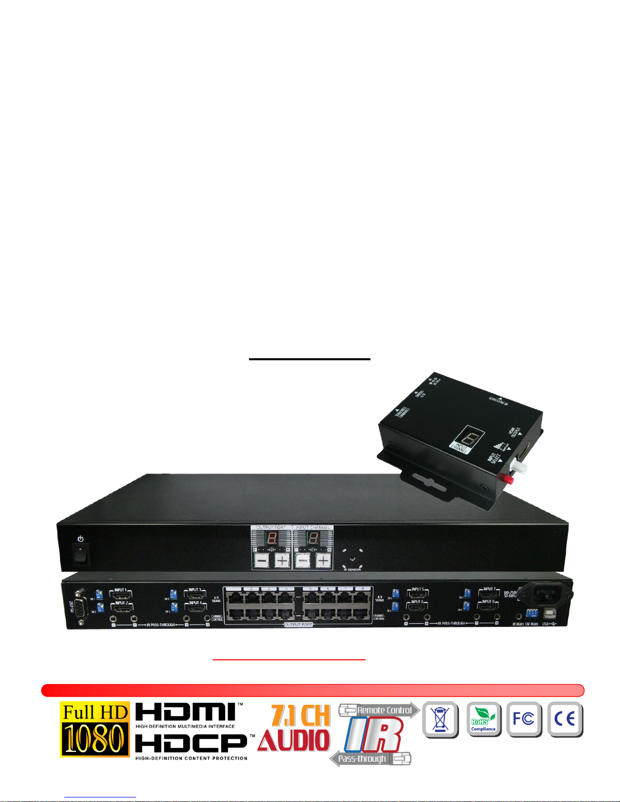
MA-5188C
8x8 HDMI over CAT5 Matrix with
IR Pass-through
User Manual
To avoid EMI issue, complete STP Cat6 cable is strongly recommended!
Made in Taiwan
Page 2
~ 1 ~
Safety and Notice
The MA-5188C v1.2/v1.3 8x8 HDMI over CAT5 Matrix with IR Pass-through has been tested for
conformance to safety regulations and requirements, and has been certified for international use. However,
like all electronic equipments, the MA-5188C should be used with care. Please read and follow the safety
instructions to protect yourself from possible injury and to minimize the risk of damage to the unit.
Follow all instructions and warnings marked on this unit.
Do not attempt to service this unit yourself, except where explained in this manual.
Provide proper ventilation and air circulation and do not use near water.
Keep objects that might damage the device and assure that the placement of this unit is on a stable
surface.
Use only the power adapter and power cords and connection cables designed for this unit.
Do not use liquid or aerosol cleaners to clean this unit. Always unplug the power to the device before
cleaning.
Page 3
~ 2 ~
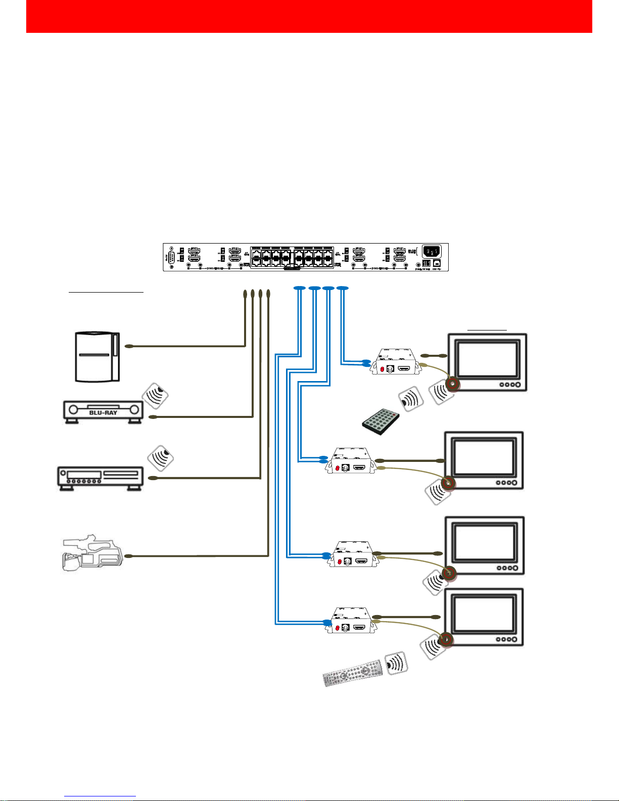
The MA-5188C 8x8 HDMI over CAT5 Matrix with IR Pass-through provides the most flexible and cost
effective solution in the market to route high definition video sources plus multi-channel (up to 7.1-channel)
digital audio from any of the eight HDMI source devices to the remote displays at the same time. Through low
cost Cat-5/5e/6 UTP/STP cables, not only high quality video and audio can be transmitted to the display sites,
but also users can switch among eight HDMI sources using the push-in button or remote control. With single
power design at the source site, each remote module is easily installed without power supply. Furthermore,
the built-in IR extension function let users can control the HDMI source devices such as the Blu-ray Disc
player or satellite receiver at display site directly!
Introduction
HDMI cable
2x CAT5e cable
8x HDTV
MA-5188RX
PS3
Blu-ray Disc Player
TiVo
HDMI Camera
IR receiver
MA-5188RX
MA-5188RX
MA-5188RX
8x HDMI Source
Matrix’s remote
control
Source device’s
remote control
IR receiver
IR receiver
IR receiver
Page 4
~ 3 ~
Features
State-of-the-art Silicon Image (Founder of HDMI) chipset embedded for upmost compatibility and
reliability
HDMI 1.2a/1.3c* compliant
HDCP compliant
Allows any source to be displayed on multiple displays at the same time
Allows any HDMI display to view any HDMI source at any time
Supports 7.1 channel digital audio
Supports default HDMI EDID and learns the EDID of displays
The matrix master can switch every output channels to any HDMI inputs by push-in button, IR remote
control, or RS-232 control
Allows controlling local HDMI sources such as DVD and TiVo by IR extender through control path at
remote receiver
Allows to control main matrix center through control line at remote receiver
Extends video signal up to 35m (115 feet) over CAT5e at 1080p and likely longer with better HDMI source
device, better grade HDMI display, and better quality solid CAT6 cable
Easy installation with rack-mounting and wall-mounting designs for master and receiver respectively
Fast response time – 2~5 seconds for channel switch
The length depends on the characteristics and quality of the cables. Higher resolutions and longer
transmission distances require low skew cables (<25ns/100m) for best performance. Unshielded
CAT6 with metal RJ-45 connectors is recommended.
Specifications & Package Contents
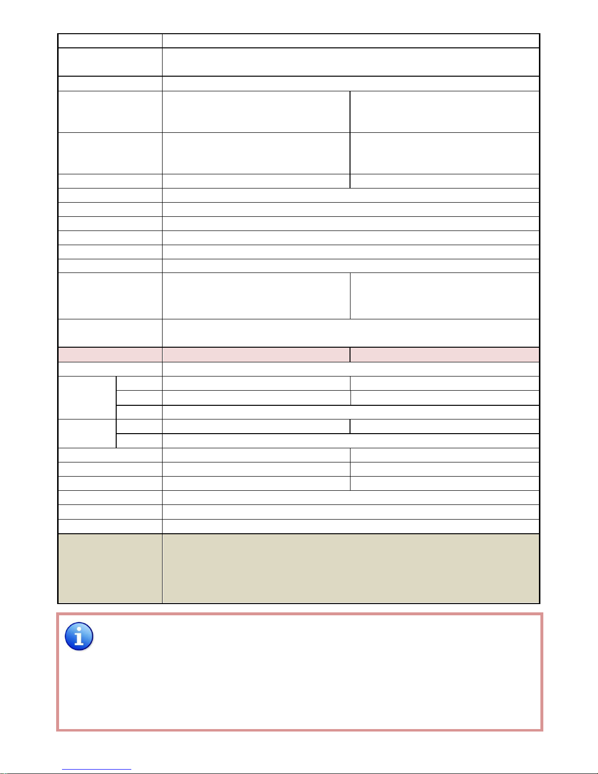
Model Name
MA-5188C v1.2 / MA-5188C v1.3
Technical
MA-5188
MA-5188RX
Role of usage
8x8 true matrix
Transmitter [TX]
Receiver [RX]
HDMI compliance
[MA-5188C v1.2] – HDMI 1.2a [MA-5188C v1.3] – HDMI 1.3c
HDCP compliance
Yes
Video bandwidth
[MA-5188C v1.2] – Single-link 165MHz [4.95Gbps]
[MA-5188C v1.3] – Single-link 225MHz [6.75Gpbs]
Video support
480i / 480p / 720p / 1080i / 1080p60
Audio support
Surround sound (up to 7.1ch) or stereo digital audio
HDMI over CAT5
transmission range
Full HD (1080p) – 35m (115ft) [CAT5e] / 40m (130ft) [CAT6]
HD (720p/1080i) – 50m (165ft) [CAT5e] / 55m (180ft) [CAT6]
HDMI equalization
N/A
8-level digital rotary control
Input TMDS signal
1.2 Volts [peak-to-peak]
*HDMI 1.2a for MA-5188C v1.2
HDMI 1.3c for MA-5188C v1.3
Page 5
~ 4 ~
Input DDC signal
5 Volts [peak-to-peak, TTL]
ESD protection
[1] Human body model — ±19kV [air-gap discharge] & ±12kV [contact discharge]
[2] Core chipset — ±8kV
PCB stack-up
4-layer board [impendence control — differential 100; single 50]
Input
8x HDMI
1x RS-232
1x RJ-45 [HDMI signal]
1x RJ-45 [Channel control]
1x IR socket for IR receiver
Output
8x RJ-45 [HDMI signal]
8x RJ-45 [Channel control]
9x IR socket for IR blaster
1x HDMI
HDMI Input selection
Push-in button / IR remote control / RS-232
Push-in button / IR remote control
HDMI source control
Controllable via IR pass-through from IR receiver at RX to IR blaster at TX
IR remote control
Electro-optical characteristics: = 25 / Carrier frequency: 38kHz
HDMI connector
Type A [19-pin female]
RJ-45 connector
WE/SS 8P8C with 2 LED indicators [TMDS & DDC channels]
RS-232 connector
DE-9 [9-pin D-sub female]
USB connector3
Standard type-B [square shape]
3.5mm connector
Earphone jack for IR blaster
[IR Main] IR control on all source devices
[IR PASS-THROUGH1~8] IR control on
individual source device
Earphone jack for IR receiver
[IR RECEIVER] Receives IR commands from
remote control
DIP switch
[MA-5188]
[SW1~SW8] 2-pin for EDID & audio mode
[SW Main] 4-pin for operation & firmware update
Mechanical
MA-5188
MA-5188RX
Enclosure
Metal case
Dimensions
(L x W x H)
Model
440 x 290 x 44mm [1’5” x 11.4” x 1.7”]
85 x 90 x 25mm [3.3” x 3.5” x 1”]
Package
528 x 398 x 130mm [1’9” x 1’4” x 5.1”]
90 x 85 x 25mm [3.5” x 3.3” x 1”]
Carton
585*242*565mm
Weight
Model
3250g [7.2 lbs]
180g [6.3oz]
Package
7.1 kg [15.6 lbs]
Fixedness
1U rack-mount with ears
Wall-mount with screws
Power supply
AC Power 100-240V
Not necessarily required1
Power consumption
60 Watts [max]
1.5 Watt [max] (provided by MA-5188)
Operation temperature
0~40C [32~104F]
Storage temperature
-20~60C [-4~140F]
Relative humidity
20~90% RH [no condensation]
Package Contents
1x MA-5188
1x IR blaster
2
2x 1U rack mounting-ear
1x IR remote control
2
1x User Manual
8x MA-5188RX
8x IR receiver
16x Wall-mounting screws
1x UL AC power cord
1
The MA-5188RX has been tested extensively and found that it doesn’t require external power supply. If
in rare situation you find it cannot work with the MA-5188, please use any +5V power adapter to plug in
the power jack and see if it can work. If not, please contact your technical support for further service.
2
Additional IR remote control and IR blaster cable can be purchased as optional accessories to control
the HDMI sources located separately.
3
USB or RS-232 control must be connected either one at a time. Connecting both types of cables may
cause command confusion.
Page 6
~ 5 ~
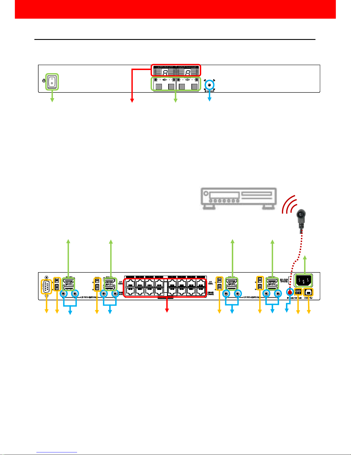
MA-5188
1. Power On/Off control switch
2. LED display for output ports and input channels
3. Front panel push buttons used to select the number of input source and display channel
4. IR SENSOR: IR sensor for receiving the IR commands from the IR remote
5. AC Power: 100-240V
6. RS-232: RS-232 control port
7. USB: USB control port
8. SW Main: DIP switches (see DIP Switch section in p.8)
9. SW 1–8: DIP switch (see DIP Switch section in p.8)
10. INPUT 1 –8: HDMI inputs
11. IR PASS-THROUGH 1–8: 3.5mm IR blaster socket for individual HDMI source control
12. OUPUT PORT 1–8: RJ-45 outputs for each output channel
13. IR Main: 3.5mm IR blaster socket for HDMI source control on all 8 inputs [default
socket for IR blaster]
Panel Descriptions
1 6 2 3 4 5 7
8 9 10
11
12
10
13
11
10 9 10
11
11 9 9
Page 7
~ 6 ~
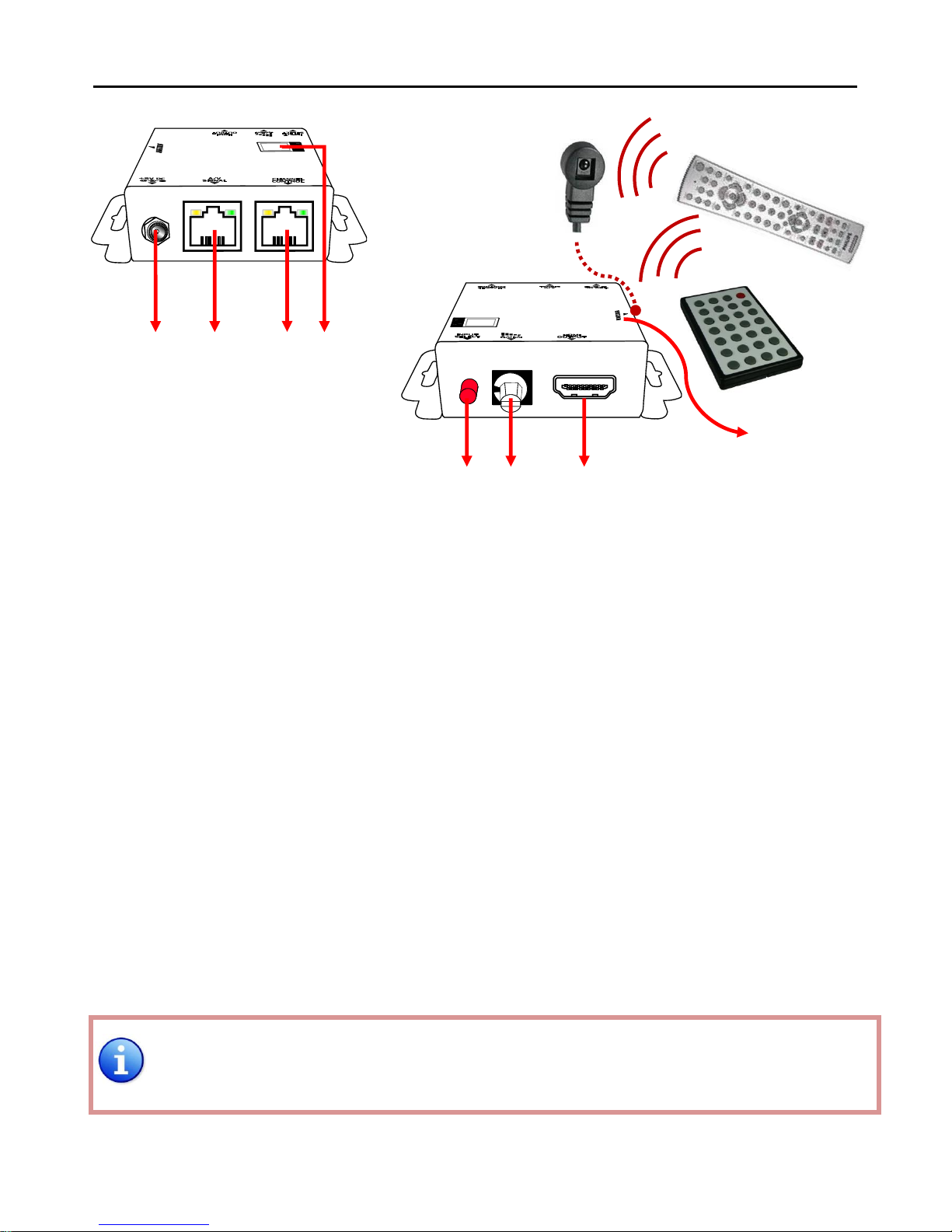
MA-5188RX
1. +5V DC: Spare power jack for over 60m transmission when the RX may need external power to
work*.
2. A/V SIGNAL: Plug in the CAT5 connected to the respective A/V SIGNAL port on the MA-5188
3. CHANNEL CONTROL: Plug in the CAT5 connected to the respective CHANNEL CONTROL port on the
MA-5188
4. INPUT CHANNEL: Display the current showing HDMI source channel
5. INPUT SELECT: Push button for switching input source channel in sequential order
6. Signal Level 0-7: Adjust the 8-level equalization control to the received HDMI signals. The HDMI
signal level varies from 0 (strongest) to 7 (weakest) for respective transmission
length from longest possible range to short distance. Please adjust the signal
level from 7 to 0 and stop turning the rotary switch whenever the audio/video is
playing normally. Inappropriate signal level setting may cause overpowering issue
that would shorten the product life significantly!
7. HDMI Output: Connect to HDTV with a HDMI cable
8. IR RECEIVER: Plug in IR receiver
*The MA-5188RX has been tested extensively and found that it doesn’t require external power supply.
If in rare situation you find it cannot work with the MA-5188, please use any +5V power adapter to
plug in the power jack and see if it can work. If not, please contact your technical support for further
service.
8
1
5
2
3
4
6
7
Page 8
~ 7 ~
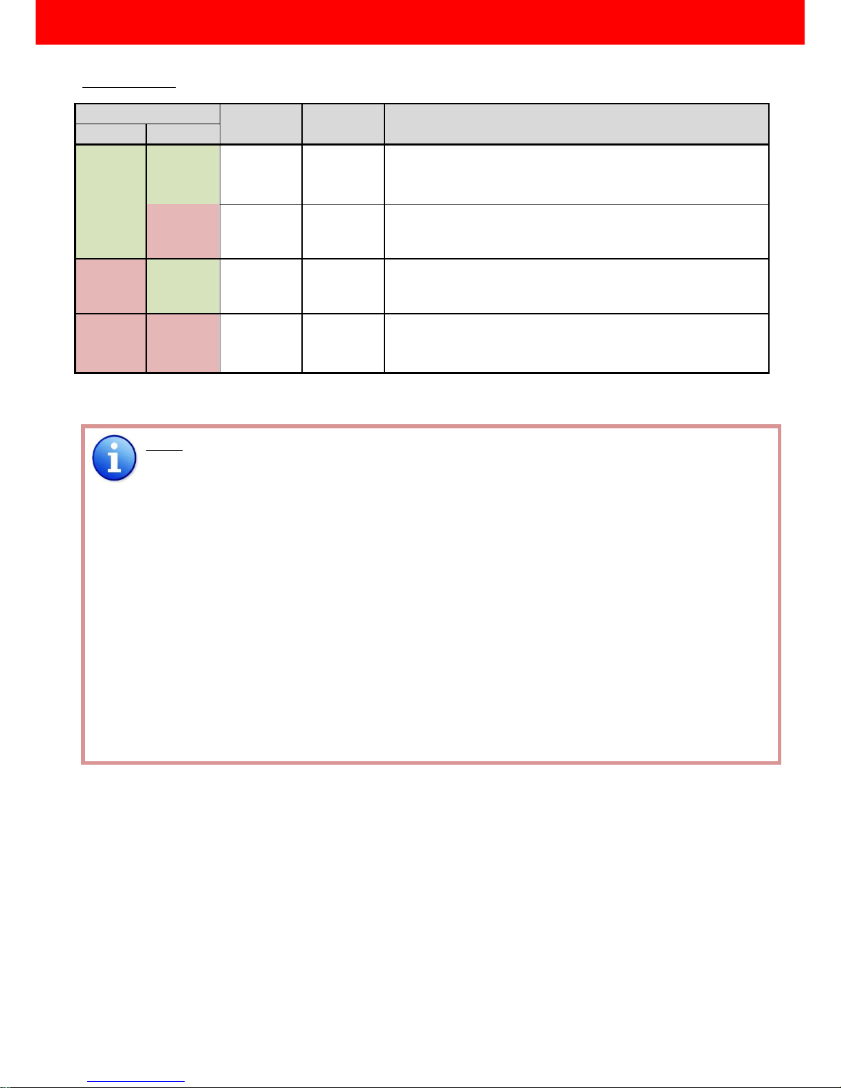
SW1-SW8 for EDID/Audio
Note
1
If the HDTV shows video but without audio, please try to set audio mode to stereo.
2 Factory default setting of [SW1]-[SW8] is pin-1 at OFF [] & pin-2 at OFF [] for 1080p video and
surround sound audio.
3 If you encounter any unsolved audio/video output problem during system installation, please turn
any [SW1]-[SW8] to pin-1 at OFF [] & pin-2 at ON [] for safe mode to enforce the system output
up to 1080p video and stereo audio for system check. However, the safe mode cannot be initiated
if your HDMI™ source is set to enforce 1080p output. In this case, please reconfigure your HDMI™
source to all resolution output for troubleshooting.
4
Bypass means the matrix will maintain playing the original format of HDMI signals in video and
perhaps audio. By setting at this mode, the users may encounter compatibility issue among different
kinds of HDMI sources and displays. If you cannot get the audio and/or video output normally at the
system installation, please change the DIP switch setting to default mode or even safe mode to
verify the functionality of the device.
5
To learn the EDID of HDMI display for respective HDMI source devices, please see the [EDID Learning]
section in the next page for more detail information.
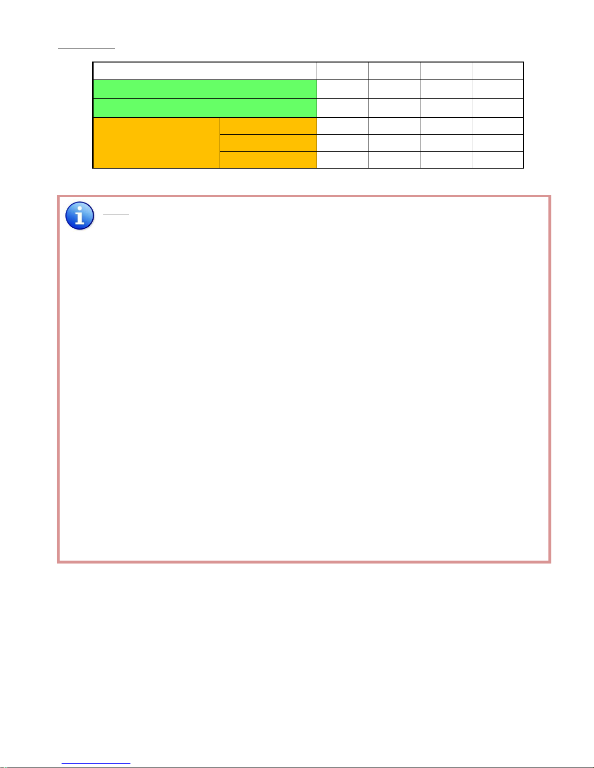
DIP Switch Position
Video
Audio
Description
Pin#1
Pin#2
OFF []
OFF []
Up to
1080p
Surround1
Default Mode2 – Up to 1080p video & surround sound
audio output up to 7.1ch (DTS-HD & Dolby TrueHD)
OFF []
ON []
Up to
1080p
Stereo
Safe Mode3 – Enforce the system output at 1080p video and
stereo audio for basic compatibility among HDTVs
ON []
OFF []
Bypass
4
Bypass4
EDID Learning Mode5 – for learning EDID from the display
while playing any received HDMI audio format
ON []
ON []
Bypass
Stereo
EDID Learning & Stereo Mode5 – for learning EDID from
the display while enforcing stereo output if any HDTV cannot
play surround sound normally
DIP Switch
Page 9
~ 8 ~
SW Main for firmware update (for technical support only)
DIP Switch Position
Pin#1
Pin#2
Pin#3
Pin#4
Normal Operation Mode [via RS-232 port]6
OFF[]
OFF[]
OFF[]
OFF[]
Normal Operation Mode [via USB port]7
OFF[]
OFF[]
OFF[]
ON[]
Firmware Update Mode8
Block A [main]
ON[]
OFF[]
OFF[]
OFF[]
Block B [remote]
ON[]
OFF[]
ON[]
OFF[]
Block C [HDMI]
ON[]
ON[]
OFF[]
OFF[]
Note
6
Factory default for SW Main is pin#1-OFF[], pin#2-OFF[], pin#3- OFF[], & pin#4-OFF[].
PLEASE MAINTAIN THIS SETTING AT ANYTIME FOR REGULAR USE VIA RS-232 CONTROL!
7
Factory default for SW Main is pin#1-OFF[], pin#2-OFF[], pin#3- OFF[], & pin#4- ON[].
PLEASE MAINTAIN THIS SETTING AT ANYTIME FOR REGULAR USE VIA USB CONTROL!
8
Sequence for firmware update
WARNING! [Firmware update only can be done via RS-232 port and connection to PC set at
COM1)
1. Power off the MA-5188. Execute the firmware update program on your PC via COM1 port
connection to the RS-232 port of the MA-5188.
2. Set the pin#1 of [SW Main] at ON[] for firmware update mode.
3. Set pin#2 and pin#3 at respective positions to assign which Block to be updated.
4. Power on the MA-5188. The firmware update program should begin this update sequence
automatically. If not, please check the RS-232 connection status between PC and MA-5188.
5. After the OK message shows up to indicate the firmware update sequence for designated
Block is complete, please turn off the MA-5188.
6. Repeat step 3 ~ step6 if you want to update the firmware of the remaining Blocks.
7. Set the [SW Main] switch position to Normal Operation Mode.
8. Power on the MA-5188.
Page 10
~ 9 ~
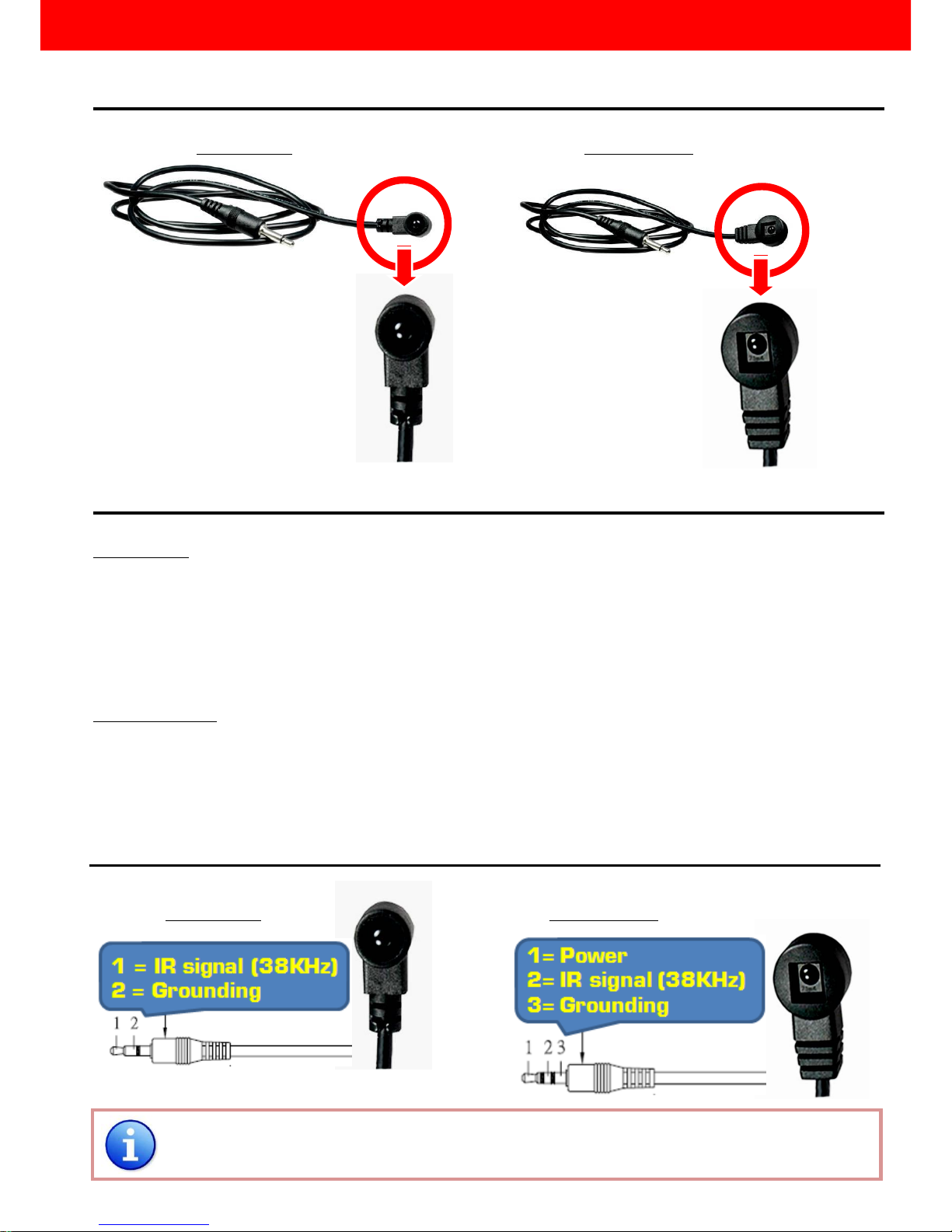
IR Extender
IR Blaster IR Receiver
IR Sockets
MA-5188
IR Main: The default location for IR blaster to transmit all IR command signals received from any of the eight
remote receivers to all of the HDMI sources.
IR PASS-THROUGH 1–8: IR blaster connected here can only transmit IR command signals from the remote
receivers that are setting at respective input channel from 1 to 8.
MA-5188RX
IR RECEIVER: IR receiver connected here can receive all IR command signals from the IR remote controls of
MA-5188C and all other HDMI source devices.
Definition of IR Earphone Jack
IR Blaster IR Receiver
You can buy any IR extension cables in the market that are compatible to the definition of the IR
sockets for the matrix if necessary for replacement use.
IR Pass-through
Page 11

~ 10 ~
Supported IR Data Format
Data Format
Suitable
Not Recommended
NEC
RC5
TOSHIBA MICOM CODE
GRUNDIG CODE
SONY 12 BIT CODE
SONY 15 BIT CODE
SONY 20 BIT CODE
RCA CODE
RCM CODE
MATSUSHITA CODE
MITSUBISHI CODE
ZENITH CODE
JVC CODE
M50560-001P
MN6125H
MN6125L
MN6014_C5D7
MN6014-C6D6
MC14457P
LC7464(AHEA)
GEMINI_CM
Page 12

~ 11 ~
MA-5188 as master
1. Connect all sources to HDMI Inputs on the 8x8 HDMI over CAT5 matrix master MA-5188
2. Connect each CHANNEL CONTROL output port on the MA-5188 to respective CHANNEL CONTROL port
on the remote receiver MA-5188RX
3. Connect each A/V SIGNAL output port on the MA-5188 to respective A/V SIGNAL input on the remote
receiver MA-5188RX
4. Connect IR blaster to the IR MAIN jack of MA-5188 and direct the IR blaster to the built-in IR receiver of
the sources
5. Connect the +5V 6A DC power supply to the MA-5188
6. Power on all HDMI sources
7. Power on the MA-5188
MA-5188RX as receiver
1. Connect each HDMI output to HDMI displays
2. Connect the A/V SIGNAL port on the MA-5188RX to the A/V SIGNAL port on the MA-5188
3. Connect the CHANNEL CONTROL port on the MA-5188RX to the CHANNEL CONTROL port on the
MA-5188
4. Connect IR receiver and place the IR receiver at the appropriate position that can receive the IR command
signals sent from the users
5. Dial the 8-level rotary control switch to adjust the HDMI signal level until the picture and sound are clear
Hardware Installation
Page 13
~ 12 ~
Source Side
Method A: Push Button
1. Use the “” or “—“ channel button on output port to select which port to be changed.
“”: change selected output port in ascending order
“—“: change selected output port in descending order
2. Push the “” or “—“ channel button on Input channel to select the HDMI input source you want to
display on this selected output port in step 1 in sequential order. Once you reach the desired input
channel you want to display on this selected output port, leave it and the setting will be effective in a few
seconds.
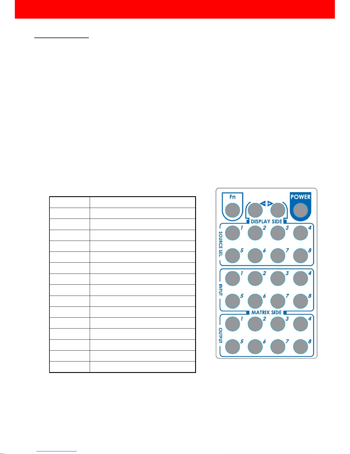
Method B: IR Remote Control
a. Firstly please push one of the INPUT buttons to choose which HDMI input source you are going to
setup. After that, you can have multiple outputs playing the same content from the selected INPUT
#1-#8 by pushing the corresponding OUTPUT buttons. The setting will be effective in a couple of
seconds.
INPUT & OUTPUT MAPPING
INPUT 1
HDMI input port #1
INPUT 2
HDMI input port #2
INPUT 3
HDMI input port #3
INPUT 4
HDMI input port #4
INPUT 5
HDMI input port #5
INPUT 6
HDMI input port #6
INPUT 7
HDMI input port #7
INPUT 8
HDMI input port #8
OUTPUT 1
HDMI output port #1
OUTPUT 2
HDMI output port #2
OUTPUT 3
HDMI output port #3
OUTPUT 4
HDMI output port #4
OUTPUT 5
HDMI output port #5
OUTPUT 6
HDMI output port #6
OUTPUT 7
HDMI output port #7
OUTPUT 8
HDMI output port #8
Channel Control
Page 14
~ 13 ~
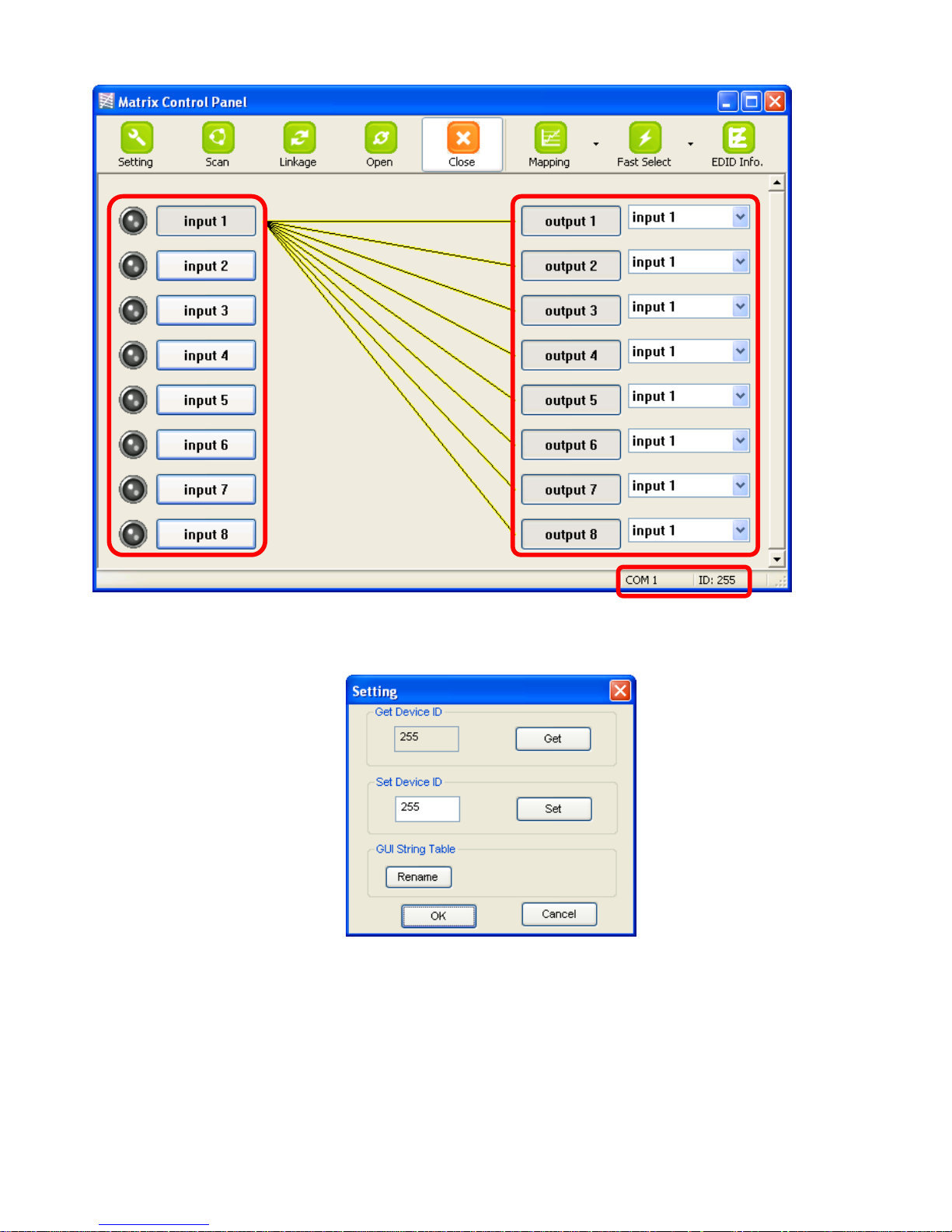
Method C: Software Control through RS-232 or USB port
Software Control Menu
1. Setting button:
Click Get button to read back device ID.
Click Set button to write device ID.
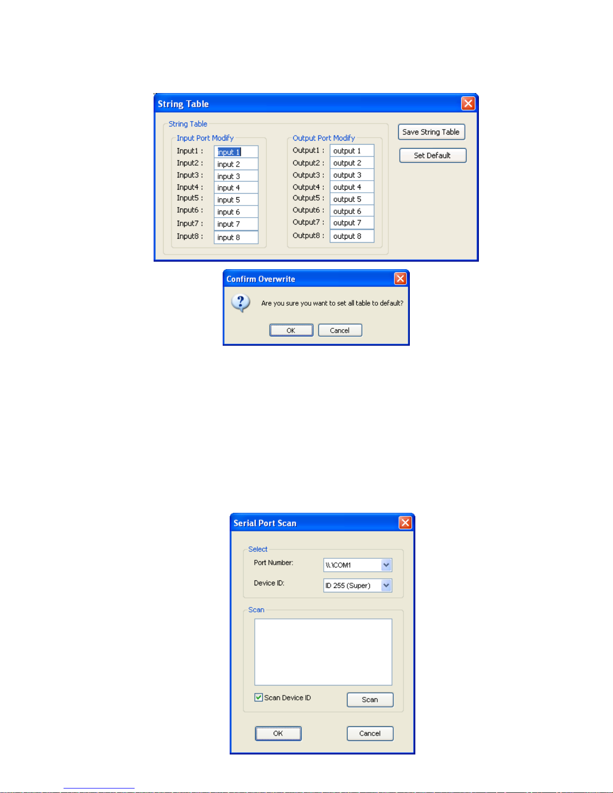
Click Rename button to open the String Table.
In the String Table, assign the captions for each input and output port for easy recognition.
For example
Rename the Input1 to “Blu-ray player”, Input2 to “Sat. receiver,” input3 to “Game console,” input4
to “AV receiver,” input5 to “HDMI camcorder,” … etc., and rename output1 to “Conf. RM1,”
output2 to “Conf. RM2,” output3 to “Lobby,” output4 to “Main projector,” … etc.
HDMI Input Source
Selection Mapping
Area
HDMI Output
Port Selection
Mapping Area
Status Indicator
Page 15
~ 14 ~
Click Save String Table to save the caption setting (turn effective after program restart).
Click Set Default to pop up the confirmation message below to erase the captions and reset the string
table back to default setting (turn effective after program restart).
2. Scan button:
Serial Port Scan
Click Scan button, the machine will scan the all COM port and show them.
Select the RS232 serial port connected to the Matrix switch.
And set device ID 255 is for all device.
Only the same device id or 255 can get the command you sent.
Click OK. Get the new status from the Matrix switch (the port you select.)
Page 16
~ 15 ~
3. Linkage button:
Click Linkage button to read back all status.
4. Open/Close button:
Click this button to close or open COM port.
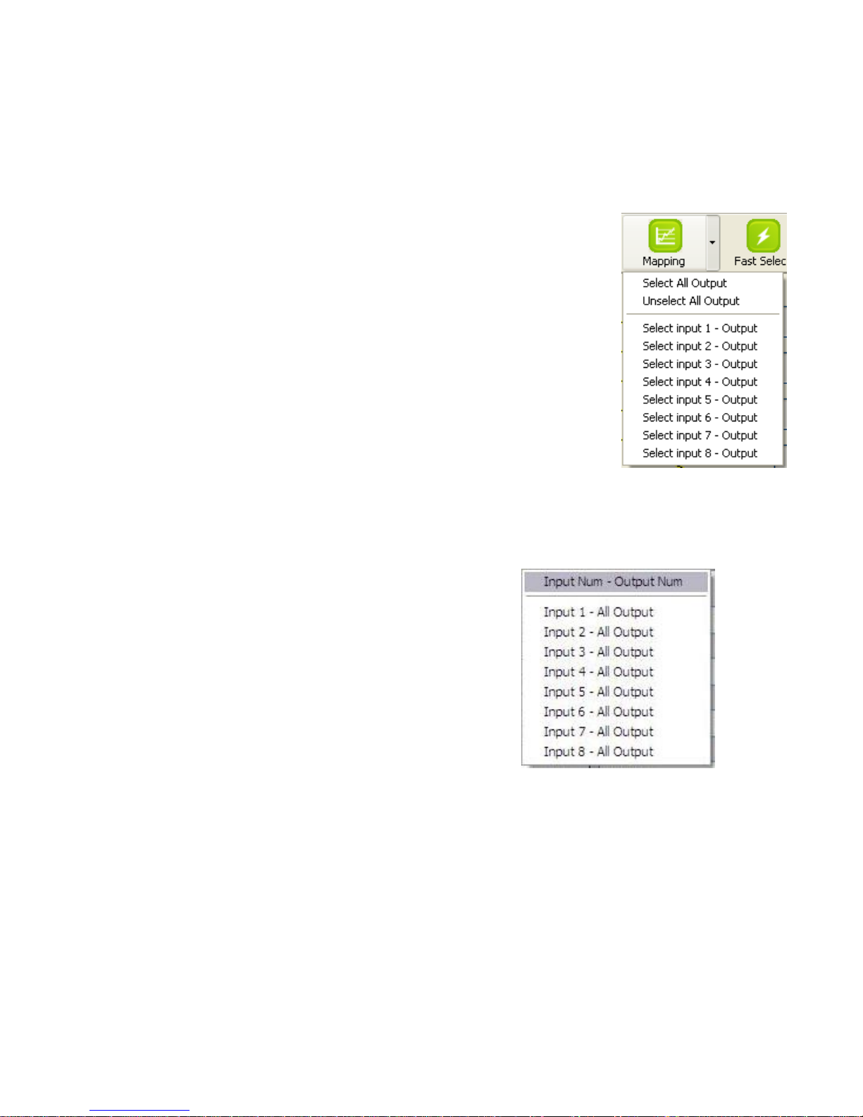
5. Mapping button:
Select All Output
Select “set all output”, and then select the source on main menu. You can
quickly set all output to the same source.
Unselect All Output
Release output selection.
Select Input1~8-Output
Select Input Source. Then select the output port icon.
For example
Select input source 1. Then select output ports one and two. The video
and audio will be sent to ports one and two.
6. Fast Select button:
Click Fast select button. Quick setting.
Input one > Output Port one
Input two > Output Port two
…..
Click Fast select pull down menu.
Select Input Num-Output Num
Input source #1 > Output port #1
Input source #2 > Output port #2 …..
Select Input* - All Output
Send the same source to all output.
Page 17
~ 16 ~
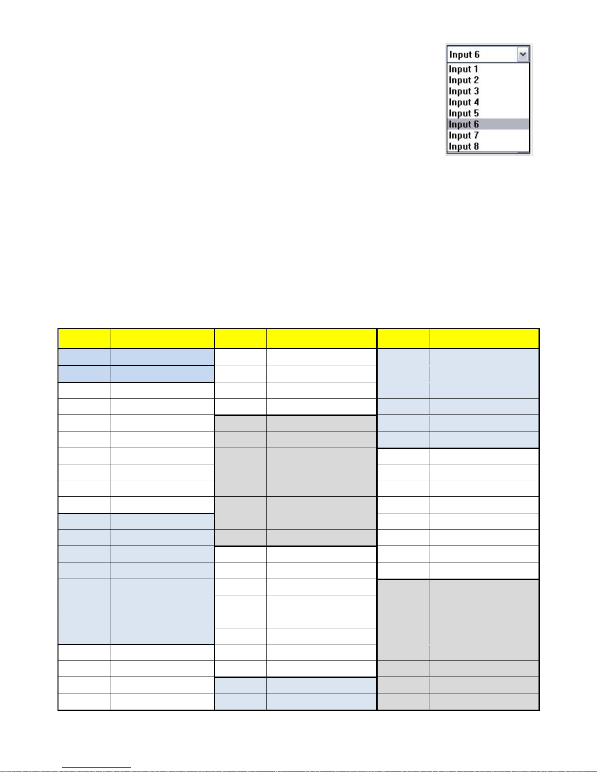
7. Output Port:
Pull down menu and select which source to be sent to this output port.
One by one setting
On main menu screen
First select input source. Then select the output ports which you want to send
the video and audio from this source. When you select the input source, the
source will change to gray. When you select the output port one by one, the
selected output port will change to gray.
The linking line will change to yellow.
Group setting
First select output ports one by one. Then select the input source. The selected output ports change the
setting at the same time.
By using Terminal:
Baud rate: 9600
Data length: 8bit
Parity check: No
Stop bit: 1
Command Set:
COMMAND
ACTION
COMMAND
ACTION
COMMAND
ACTION
ST
System Status
C5
Output C select Input 5
F3
Output F select Input 3
VR
Firmware Version
C6
Output C select Input 6
F4
Output F select Input 4
A1
Output A select Input 1
C7
Output C select Input 7
F5
Output F select Input 5
A2
Output A select Input 2
C8
Output C select Input 8
F6
Output F select Input 6
A3
Output A select Input 3
D1
Output D select Input 1
F7
Output F select Input 7
A4
Output A select Input 4
D2
Output D select Input 2
F8
Output F select Input 8
A5
Output A select Input 5
D3
Output D select Input 3
G1
Output G select Input 1
A6
Output A select Input 6
D4
Output D select Input 4
G2
Output G select Input 2
A7
Output A select Input 7
D5
Output D select Input 5
G3
Output G select Input 3
A8
Output A select Input 8
D6
Output D select Input 6
G4
Output G select Input 4
B1
Output B select Input 1
D7
Output D select Input 7
G5
Output G select Input 5
B2
Output B select Input 2
D8
Output D select Input 8
G6
Output G select Input 6
B3
Output B select Input 3
E1
Output E select Input 1
G7
Output G select Input 7
B4
Output B select Input 4
E2
Output E select Input 2
G8
Output G select Input 8
B5
Output B select Input 5
E3
Output E select Input 3
H1
Output H select Input 1
B6
Output B select Input 6
E4
Output E select Input 4
H2
Output H select Input 2
B7
Output B select Input 7
E5
Output E select Input 5
H3
Output H select Input 3
B8
Output B select Input 8
E6
Output E select Input 6
H4
Output H select Input 4
C1
Output C select Input 1
E7
Output E select Input 7
H5
Output H select Input 5
C2
Output C select Input 2
E8
Output E select Input 8
H6
Output H select Input 6
C3
Output C select Input 3
F1
Output F select Input 1
H7
Output H select Input 7
C4
Output C select Input 4
F2
Output F select Input 2
H8
Output H select Input 8
Page 18
~ 17 ~
Display Side
Method A: Push button for switching input channels
Press the INPUT SELECT push button to switch the input source on the respective output port connected to
the matrix receiver in sequential order. The selected input source will be displayed on the LED of INPUT
CHANNEL.
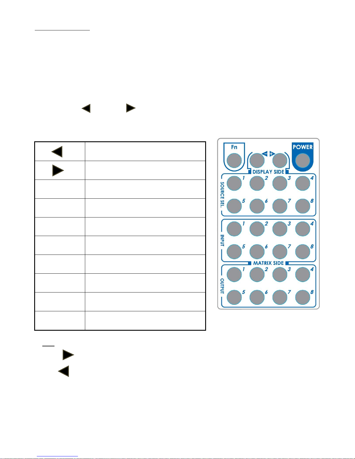
Method B1: IR remote control for switching input channels
Please decide which input channel to be selected by pressing Source Selection 1 to Source Selection 8. Or
you can use left — and right button to enter IR control mode and select the input channel in
ascending and descending order respectively. The setting will be effective in a couple of seconds.
Switch input port in descending order*
Switch input port in ascending order*
SOURCE SEL. 1
Switch the display channel at the remote
site to input port 1
SOURCE SEL. 2
Switch the display channel at the remote
site to input port 2
SOURCE SEL. 3
Switch the display channel at the remote
site to input port 3
SOURCE SEL. 4
Switch the display channel at the remote
site to input port 4
SOURCE SEL. 5
Switch the display channel at the remote
site to input port 5
SOURCE SEL. 6
Switch the display channel at the remote
site to input port 6
SOURCE SEL. 7
Switch the display channel at the remote
site to input port 7
SOURCE SEL. 8
Switch the display channel at the remote
site to input port 8
Note
Right ( ) button to switch input source in ascending order (1, 2, 3, 4, 5, 6, 7, 8, 1, 2, ......)
Left ( ) button to switch input source in descending order (1, 8, 7, 6, 5, 4, 3, 2, 1, 2, ......)
Method B2: IR remote control for controlling the HDMI sources
Users can use the corresponding IR remotes to control respective BD players, DVD players, or any HDMI
input devices including MA-5188C itself with IR control at any display site.
—
—
Page 19
~ 18 ~
The EDID learning function is only necessary whenever you encounter any display on the HDMI output
port that cannot play audio and video properly. Because the HDMI source devices and displays may have
various level of capability in playing audio and video, the general principle is that the source device will output
the lowest standards in audio format and video resolutions to be commonly acceptable among all HDMI
displays. In this case, a 720p stereo HDMI signal output would be probably the safest choice. Nevertheless,
the user can force the matrix to learn the EDID of the lowest capable HDMI display among others to make sure
all displays are capable to play the HDMI signals normally by performing the procedures stated below.
SW1-SW8 Pin#1 and Pin#2 must be set “ON” & “OFF” for EDID Learning Mode
Method 1: Manually connect HDMI displays to HDMI input ports
1. Power up the matrix master unit. Connect the HDMI display that its EDID needs to be learned to any of the
HDMI INPU1-INPU8 port where your source device has trouble to show the picture normally.
2. To learn the display’s EDID for source device connected to respective HDMI INPU1-INPUT8 port, pull
both pins of respective DIP switch SW1-SW8 up-and-down to stay at ON[]-OFF[] and wait for
about 5 seconds to complete the EDID learning process. You DON’T NEED to pull up the DIP switch again
unless you want to learn another display’s EDID by pulling both DIP switch pin-1 & pin-2 of SW1-SW8
up-and-down one more time.
3. Repeat step1 & step2 if you want to learn the EDID of this HDMI display on any other HDMI input ports
that have same trouble playing the audio/video properly.
DIP Switch Position
Video
Audio
Description
Pin#1
Pin#2
ON []
OFF []
Bypass
Bypass
EDID Learning – for learning EDID from the receiver
EDID Learning
Page 20

~ 19 ~
Method 2: Use the front panel of the master unit
Button
Function
Output Port
EDID will be read from display via the connected receiver unit from the
respective output port
Input Channel
The EDID will be sent to the input source connected to respective
HDMI input port
One by One learning
1. Select the desired Output Port and Input Channel that you want the EDID of the display
connected to this specified output port can be learned for the specified input channel.
2. Press the “+” button of the Output Port and “−” button of the Input Channel” at the same time
for 2 seconds.
3. Release these two buttons. The EDID will be read from the receiver unit connected to the display
and sent the Output Port then written to the chosen Input Channel.
4. If the operation is successful, the Input Channel will show “O” (OK). If the operation is not
successful, it will show “F” (failure).
One to All learning
1. Press the “” button of the Output Port and the “” button of the Input Channel” at the same
time for 2 seconds.
2. Release these two buttons. . The EDID will be read from the receiver unit connected to the display
and sent the Output Port then written to all eight Input Channels.
3. If the operation is successful, the Input Channels will show “O” (OK). If the operation is not
successful, it will show “F” (failure).
Page 21
~ 20 ~
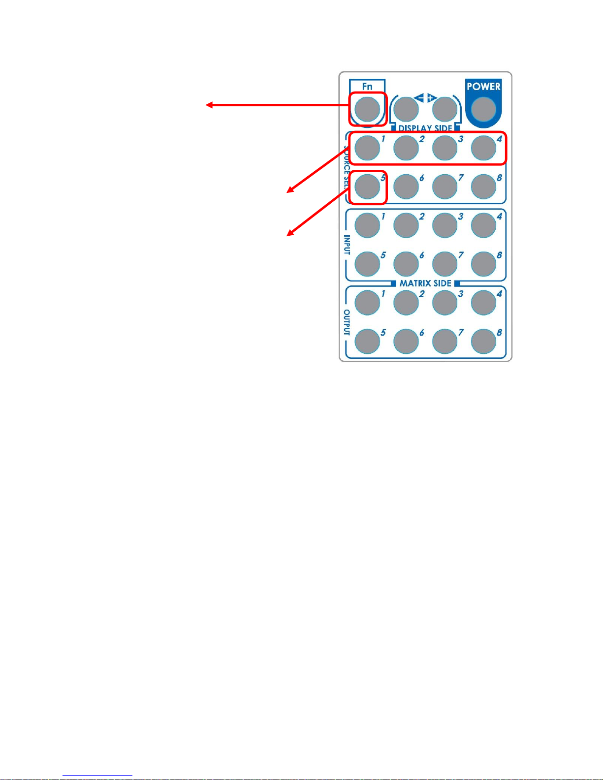
Method 3: Via IR remote control in the receiver side
Step1. Press FN key first
Step2. Wait until the LED on the
receiver showing “U”
Step3. Then press the button
“1” Default A(1080P ,7.1ch audio),
“2” Default B(1080P, stereo audio),
“3” Default C(720P, stereo audio)
“4” Default D(DVI Mode),
“5” Learning EDID from this display to
the selected input
Step4. If the procedure is successful,
the LED of will show “0”, otherwise it
will be “F” to indicate failure
Page 22
~ 21 ~
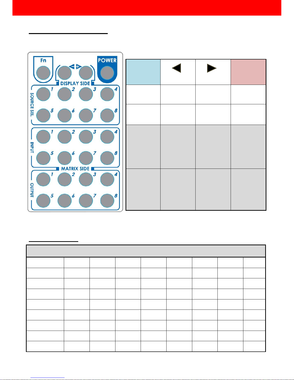
Default Custom Code — IR2 Code: 00 FF
Custom Code — IR3 Code: 0x12 0x21
Custom Code: 0x12 0x21
Output 1
Output 2
Output 3
Output 4
Output 5
Output 6
Output 7
Output 8
Source 1
0xA1
0xB1
0xC1
0xD1
0xE1
0xF1
0x11
0x21
Source 2
0xA2
0xB2
0xC2
0xD2
0xE2
0xF2
0x12
0x22
Source 3
0xA3
0xB3
0xC3
0xD3
0xE3
0xF3
0x13
0x23
Source 4
0xA4
0xB4
0xC4
0xD4
0xE4
0xF4
0x14
0x24
Source 5
0xA5
0xB5
0xC5
0xD5
0xE5
0xF5
0x15
0x25
Source 6
0xA6
0xB6
0xC6
0xD6
0xE6
0xF6
0x16
0x26
Source 7
0xA7
0xB7
0xC7
0xD7
0xE7
0xF7
0x17
0x27
Source 8
0xA8
0xB8
0xC8
0xD8
0xE8
0xF8
0x18
0x28
Function
0x17
0x0A
0x0C
POWER
0x02
SOURCE SEL. 1
0x54
SOURCE SEL. 2
0x55
SOURCE SEL 3
0x56
SOURCE SEL. 4
0x01
SOURCE SEL. 5
0x57
SOURCE SEL. 6
0x58
SOURCE SEL. 7
0x59
SOURCE SEL. 8
0x06
INPUT 1
0x18
INPUT 2
0x5B
INPUT 3
0x19
INPUT 4
0x07
INPUT 5
0x1B
INPUT 6
0x5A
INPUT 7
0x1A
INPUT 8
0x04
OUTPUT 1
0x0E
OUTPUT 2
0x0D
OUTPUT 3
0x12
OUTPUT 4
0x05
OUTPUT 5
0x1C
OUTPUT 6
0x1D
OUTPUT 7
0x1F
OUTPUT 8
0x1E
IR Discrete Code
—
Page 23
~ 22 ~
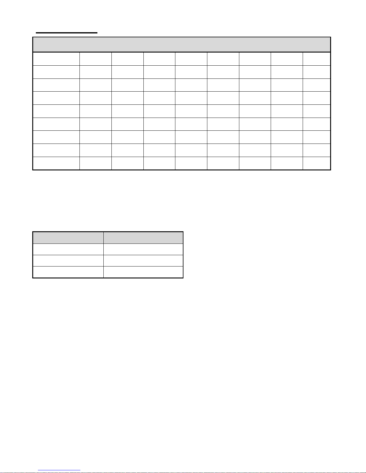
Custom Code — IR4 Code: 0x13 0x31
Custom Code: 0x13 0x31
Output 1
Output 2
Output 3
Output 4
Output 5
Output 6
Output 7
Output 8
Source 1
0xAE
0xBE
0xCE
0xDE
0xEE
0xFE
0x1E
0x2E
Source 2
0xAD
0xBD
0xCD
0xDD
0xED
0xFD
0x1D
0x2D
Source 3
0xAC
0xBC
0xCC
0xDC
0xEC
0xFC
0x1C
0x2C
Source 4
0xAB
0xBB
0xCB
0xDB
0xEB
0xFB
0x1B
0x2B
Source 5
0xAA
0xBA
0xCA
0xDA
0xEA
0xFA
0x1A
0x2A
Source 6
0xA9
0xB9
0xC9
0xD9
0xE9
0xF9
0x19
0x29
Source 7
0xA8
0xB8
0xC8
0xD8
0xE8
0xF8
0x18
0x28
Source 8
0xA7
0xB7
0xC7
0xD7
0xE7
0xF7
0x17
0x27
Note: Using terminal to set Custom Code
Example: Set custom code from 0x01 0xEE to 0x13 0x31
>>IR4 -------------- command (using RS-232 terminal command mode)
>>IR4 -------------- echo
Command
Custom Code
IR2
0x00 0xFF
IR3
0x12 0x21
IR4
0x13 0x31
For further information, please check the installation CD.
Page 24
~ 23 ~
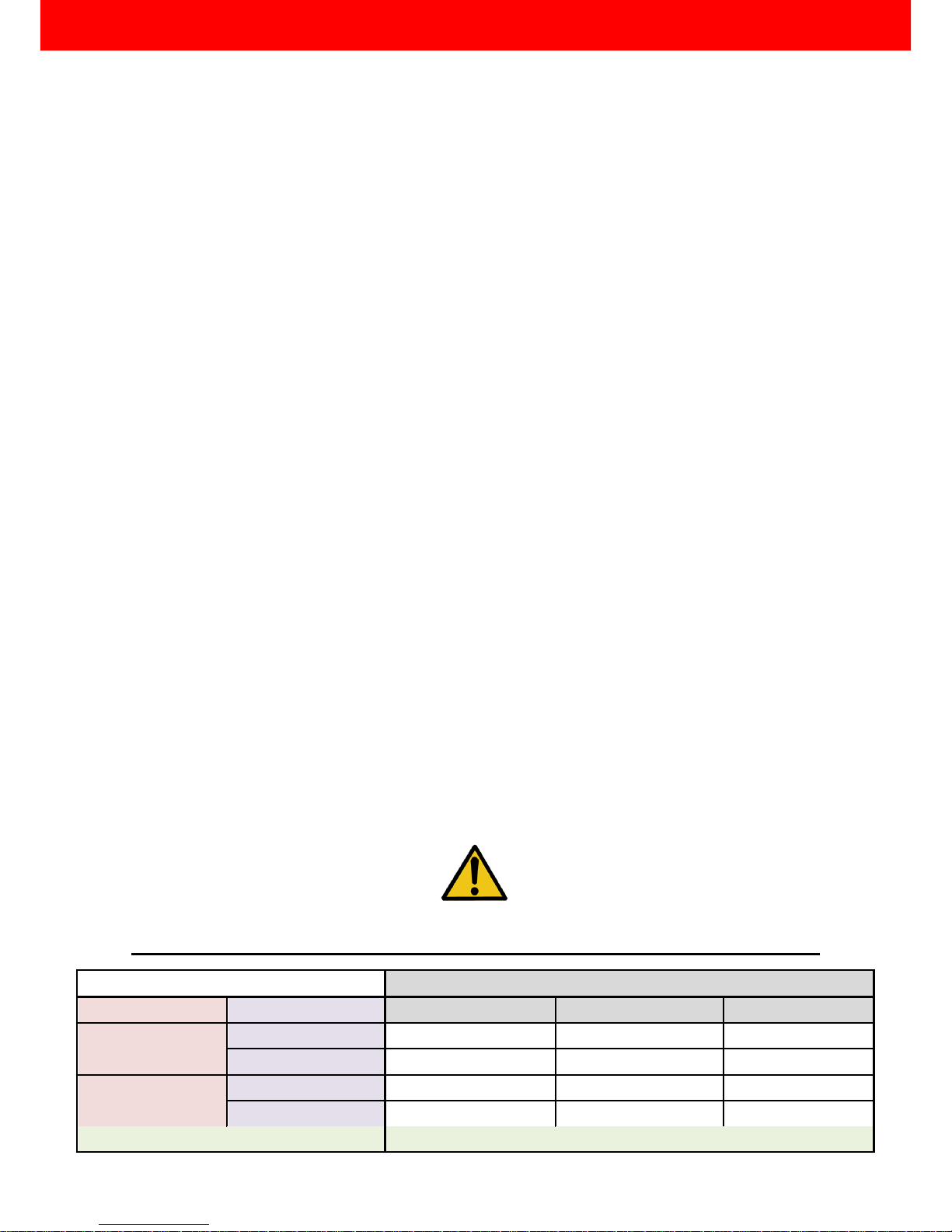
1. When adjusting the signal level on the receiver unit, please dial the rotary control switch from 7 to 0
and stop turning the rotary switch whenever the audio/video is playing normally. Inappropriate signal
level setting may cause overpowering issue that would shorten the product life significantly!
2. If the DVI or HDMI device requires the EDID information, please use EDID Reader/Writer to retrieve and
provide DVI or HDMI display EDID information.
3. All HDMI over CAT5 transmission distances are measured using Belden 1583A CAT5e 125MHz UTP
cable and ASTRODESIGN Video Signal Generator VG-859C.
4. The transmission length is largely affected by the type of Cat-5/5e/6 cables, the type of HDMI sources,
and the type of HDMI display. The testing result shows solid UTP cables (usually in the form of 300m
[1,000ft] bulk cables) can transmit a lot longer signals than stranded UTP cables (usually in the form of
fixed length patch cords). Shielded STP cables are better suited than unshielded UTP cables. A solid
UTP Cat-5e cable shows longer transmission range than stranded STP Cat-6 cable. For long extension
applications, solid UTP/STP cables are the only viable choice.
5. EIA/TIA-568-B termination (T568B) for Cat-5/5e/6 cables is recommended for better performance.
6. To reduce the interference among the unshielded twisted pairs of wires in Cat-5/5e/6 cable, one can
use shielded STP cables to improve EMI problems, which is worsen in long transmission.
7. Because the quality of the CAT5/6 cables has the major effect on how long the transmission limit can
achieve and how good is the received picture quality, the actual transmission range is subject to one’s
choice of Cat-5/5e/6 cables. For desired resolutions greater than 1080i or 1280x1024, a Cat-6 cable is
recommended.
8. If your HDMI display has multiple HDMI inputs, it is found that the first HDMI input [HDMI input #1]
generally can produce better transmission performance among all HDMI inputs.
9. The MA-5188RX has been tested extensively and found that it doesn’t require external power supply. If
in rare situation you find it cannot work with the MA-5188, please use any +5V power adapter to plug
in the power jack and see if it can work. If not, please contact your technical support for further service.
10. Additional IR remote controls and IR blaster cables can be purchased as optional accessories to
control the HDMI sources located separately.
Performance Guide for HDMI over CAT5/6 Cable Transmission
Performance rating
Type of CAT5/6 cable
Wiring
Shielding
CAT5
CAT5e
CAT6
Solid
Unshielded (UTP)
Shielded (STP)
Stranded
Unshielded (UTP)
Shielded (STP)
Termination
Please use EIA/TIA-568-B termination (T568B) at any time
Notice
Page 25

~ 24 ~
1. The quality of output video is not good enough, how can I do?
Please adjust the 8-level equalization on the receiver units. The HDMI signal level varies from 0 (strongest)
to 7 (weakest) for respective transmission length from longest possible range to short distance. It is
recommended to switch from 7 to 0 to find the optimal visual experience.
2. Can I use any kind of LAN cable?
Please check the NOTICE section for more information about how to pick up a suitable cable.
3. Can every TV work with the HDMI matrix?
Basically, the answer is YES. But if your TV can not support 1080p, please refer the EDID LEARNING
section to learn EDID from your TV.
4. What is EDID? Why do I need to learn EDID?
EDID contains the whole information of the display such as the resolution and audio setting which this
display can support. Therefore, based on the EDID information, media player will pick up the most
suitable resolution and audio setting to the display. In order to faithfully transmit the EDID information
from display to the media player, learning EDID from display to this device is necessary.
5. What should I do to learn EDID for the matrix?
Due to the limitation of HDMI, the source device can only output one format of video and audio. In other
words, the source device cannot output 720p and 1080p video at the same time, or output stereo and
surround sound at the same time. Therefore, you may need to manually setup the DIP switch for each
HDMI input for desirable audio/video output format. The mechanism of EDID Learning is to pick up the
HDMI display with the lowest capability among the ones you would use for this input source. For example,
if user would like to play the Input-2 upon output-3, output-5 and output-8, and only output-5 cannot
support 1080p [support up to 720p only], please learn the EDID from the display connected to the
output-5 at the Input-2 port. Of course, if outpt-5 could get the HDMI signals from every HDMI input,
please learn EDID information from output5 to all eight HDMI inputs. For more information about EDID
Learning, please refer to EDID LEARNING section.
6. My TV can support 1080p, but why there is no audio?
The default setting of this device is 1080p & 7.1ch audio, so there would be a problem if the TV cannot
support 7.1ch audio. Please change the DIP switch of the chosen input from Default Mode to Safe Mode.
FAQ
Page 26
~ 25 ~
7. When I set an audio amplifier (AV receiver) between TV and the matrix to extract 7.1ch audio, but why
there is still no audio?
Basically, the default DIP switch setting of the chosen input can support 7.1ch audio, but the problem is
that the EDID of the amplifier still cannot match the default setting. Therefore, the best method is to learn
EDID from the amplifier directly. Please refer to EDID LEARNING section and follow the steps to learn the
EDID. When learning EDID from the amplifier, user just needs to connect the matrix and amplifier. Please
don’t connect HDMI cable between amplifier and TV when the EDID learning is proceeding.
8. When I play the same content upon multi-displays, why only the TV equipped with amplifier can have
7.1ch audio, and the others don’t have 7.1ch audio even no stereo?
Due to the limitation of HDMI, the source only can choose one video and one audio format to play, which
can be either 1080p and 7.1ch or 1080p and stereo audio. It means when the user sets the matrix at
1080p and 7.1ch, the source will only play the content under this format. Therefore if the TV cannot
decode 7.1ch audio, there is definitely no audio.
9. Is there an easier method that can allow this matrix switcher to work properly?
Please refer to the third method of EDID learning to switch among different default EDID profiles at the
remote side. Through the switching from 1st to 5th default EDID profile, stay with the one that can get the
audio and video as you wish.
10. I have tried every method above, why there is still no audio anyway?
It is because the media player cannot recognize the EDID of the display. Therefore please adjust the DIP
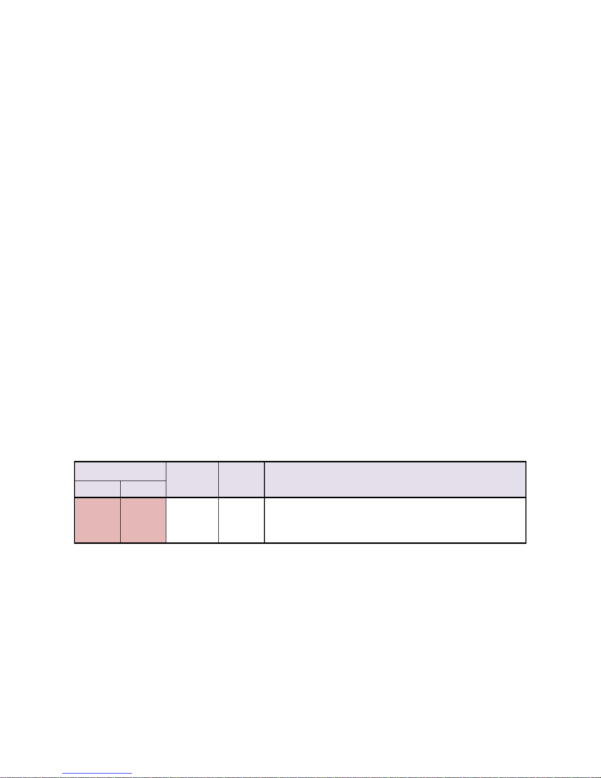
switch of this input to EDID Learning & Stereo Mode to have audio properly.
SW1-8 Position
Video
Audio
Description
Pin 1
Pin 2
ON []
ON []
Bypass
Stereo
EDID Learning & Stereo Mode – for learning EDID from
the display while enforcing stereo output if any HDTV
cannot play surround sound normally
Page 27
~ 26 ~
The SELLER warrants the MA-5188C v1.2/v1.3 8x8 HDMI over CAT5 Matrix with IR Pass-through to be
free from defects in the material and workmanship for 1 year from the date of purchase from the SELLER or an
authorized dealer. Should this product fail to be in good working order within 1 year warranty period, the
SELLER, at its option, repair or replace the unit, provided that the unit has not been subjected to accident,
disaster, abuse or any unauthorized modifications including static discharge and power surge. This warranty is
offered by the SELLER for its BUYER with direct transaction only. This warranty is void if the warranty seal on
the metal housing is broken.
Unit that fails under conditions other than those covered will be repaired at the current price of parts and
labor in effect at the time of repair. Such repairs are warranted for 90 days from the day of reshipment to the
BUYER. If the unit is delivered by mail, customers agree to insure the unit or assume the risk of loss or
damage in transit. Under no circumstances will a unit be accepted without a return authorization number.
The warranty is in lieu of all other warranties expressed or implied, including without limitations, any
other implied warranty or fitness or merchantability for any particular purpose, all of which are expressly
disclaimed.
Proof of sale may be required in order to claim warranty. Customers outside Taiwan are responsible for
shipping charges to and from the SELLER. Cables and power adapters are limited to a 30 day warranty and
must be free from any markings, scratches, and neatly coiled.
The content of this manual has been carefully checked and is believed to be accurate. However, The
SELLER assumes no responsibility for any inaccuracies that may be contained in this manual. The SELLER will
NOT be liable for direct, indirect, incidental, special, or consequential damages resulting from any defect or
omission in this manual, even if advised of the possibility of such damages. Also, the technical information
contained herein regarding the MA-5188C v1.2/v1.3 features and specifications is subject to change without
further notice.
Limited Warranty
 Loading...