

Golze Engineering ADL150 Installation Manual
ADL150 User and Installation Manual 1 / 12 Revision 1.01 - 28.03.2018
ADL150
User and Installation Manual
Version 1.01
28.03.2018

ADL150 User and Installation Manual 2 / 12 Revision 1.01 - 28.03.2018
1 Version History
Version 1.00 published 15.02.2017
Version 1.01 published 28.03.2018
2 Page Index
This manual contains numbered pages 1 to 12.
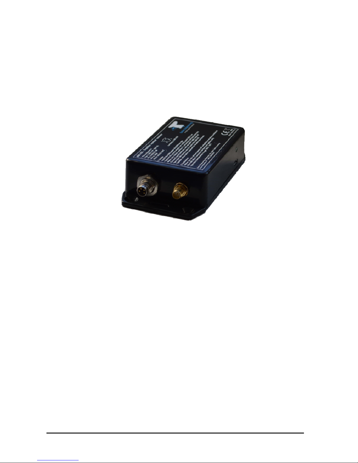
3 General Description
The ADL150 is a satellite weather receiver for permanent installation with separate
antenna.
4 Emergency procedures
If you suspect any malfunction of the ADL150 or interference with other aircraft
systems, deactivate the device by pulling / deactivating the aircraft circuit breaker for
the device or pulling the cigarette lighter plug whichever is applicable. Do not reactivate
the device until the problem has been investigated and resolved on the ground.
In case of a generator failure or similar situation requiring electric load shedding,
deactivate the ADL150 by pulling / deactivating the aircraft circuit breaker for the device
or pulling the cigarette lighter plug whichever is applicable.
5 Certification ADL150
The ADL150 can be installed permanently in certified aircraft if a suitable minor change
is used. The device itself does not come with any certification. Please consult the minor
change documentation for details.
6 Disclaimer
The ADL150 is provided as a non certified component. The only basis on witch it can
be installed is an appropriate minor change. It is the sole responsibility of the user and
installer that is installed and used in a legal way. The device may stop working at any
time. Do not undertake flights you would not undertake without the ADL150.
7 Warning!
While we do everything we can to ensure quality the ADL150 devices might not work at
any time. In addition they may display false information. Never penetrate weather
based on the information provided by the ADL150. This information is for situational
awareness only. The device features a GPS moving map system. This system is
designed to display the aircraft position in relation to the weather data. It is not
designed as a means of primary navigation. Especially the build in database is not
updated in a regular aviation cycle. It is also not maintained to the standards of certified
aviation databases.
ADL150 User and Installation Manual 3 / 12 Revision 1.01 - 28.03.2018
8 The Iridium satellite service
Before you can use the ADL150 you have to subscribe to one of our Iridium satellite
service plans. Please login to the ADL customer portal to order the different service
plans:
https://www.ing-golze.de/login.jsp
If you have no login yet please contact us by email at adl@ing-golze.de.
PLEASE NOTE: The ADL150 will show satellite signal even without an active satellite
service plan and will be able to transmit data. But this data will not be processed and
the device will receive no answer.
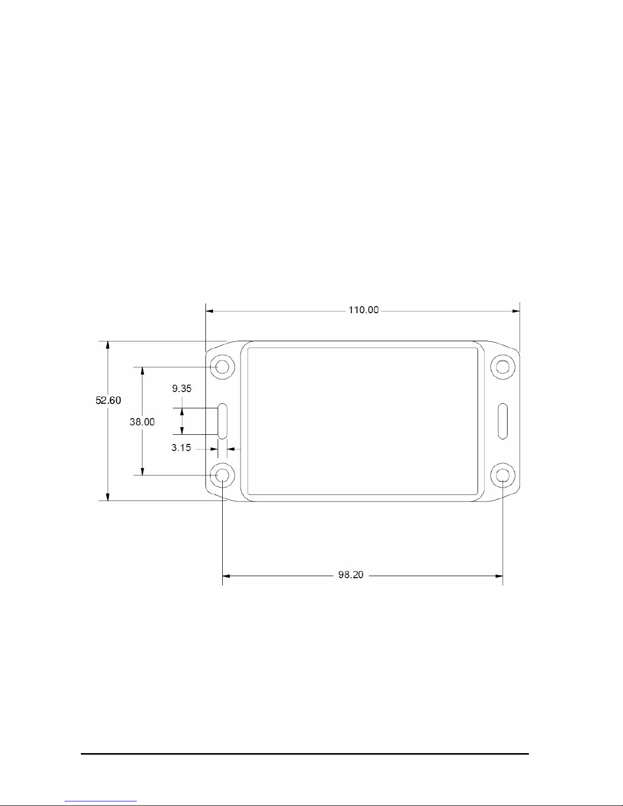
9 Dimensions and mounting details
Figure 1 ADL150 footprint (all measurements are given millimeters)
ADL150 User and Installation Manual 4 / 12 Revision 1.01 - 28.03.2018
Figure 2 ADL150 side view
Attach the ADL150 with four M4 screws or similar imperial mounting hardware. Provide
enough clearance so the Micro USB port can be reached for later firmware updates.
Pay attention not to interfere with any other aircraft systems like steering, wiring etc.
Make sure the device is sufficiently attached so it can not become lose in flight.
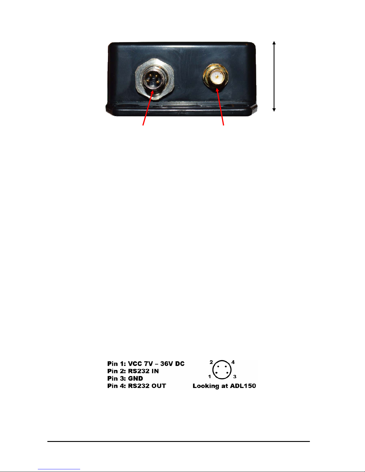
10 Power connector
The USB micro socket on the side of the ADL150 will not power up the device. It
is used for firmware updates only. Connecting a device through the USB port will
deactivate the ADL150 WiFi and it will enter the update mode.
The ADL150 requires two connections. First the device has to be connected to a
continuous power source. It will accept 7-36 Volt and consumes about 1 Watt. The
ADL150 has got an internal emergency fuse but it should be protected externally
typically by a 1 Amp circuit breaker. This circuit breaker should also be accessible in
flight so the crew can deactivate the ADL150 if any malfunction is suspected.
As an alternative a portable cigarette lighter power cable in available. Those power
cables are identical to ADL140 power cables.
The green LED on the side of the ADL150 enclosure will illuminate if power is supplied.
Figure 3 ADL150 power connector pins
As an option the ADL150 can be supplied with RS232 Aviation data or NMEA data from
an on board navigation system. If "FPL IN" in activated in the ADLConnect app the
26mm
Antenna
Power
 Loading...