

Page 1
KB300 / KB350 with FS560
Translation of the original operating instruction and spare parts list
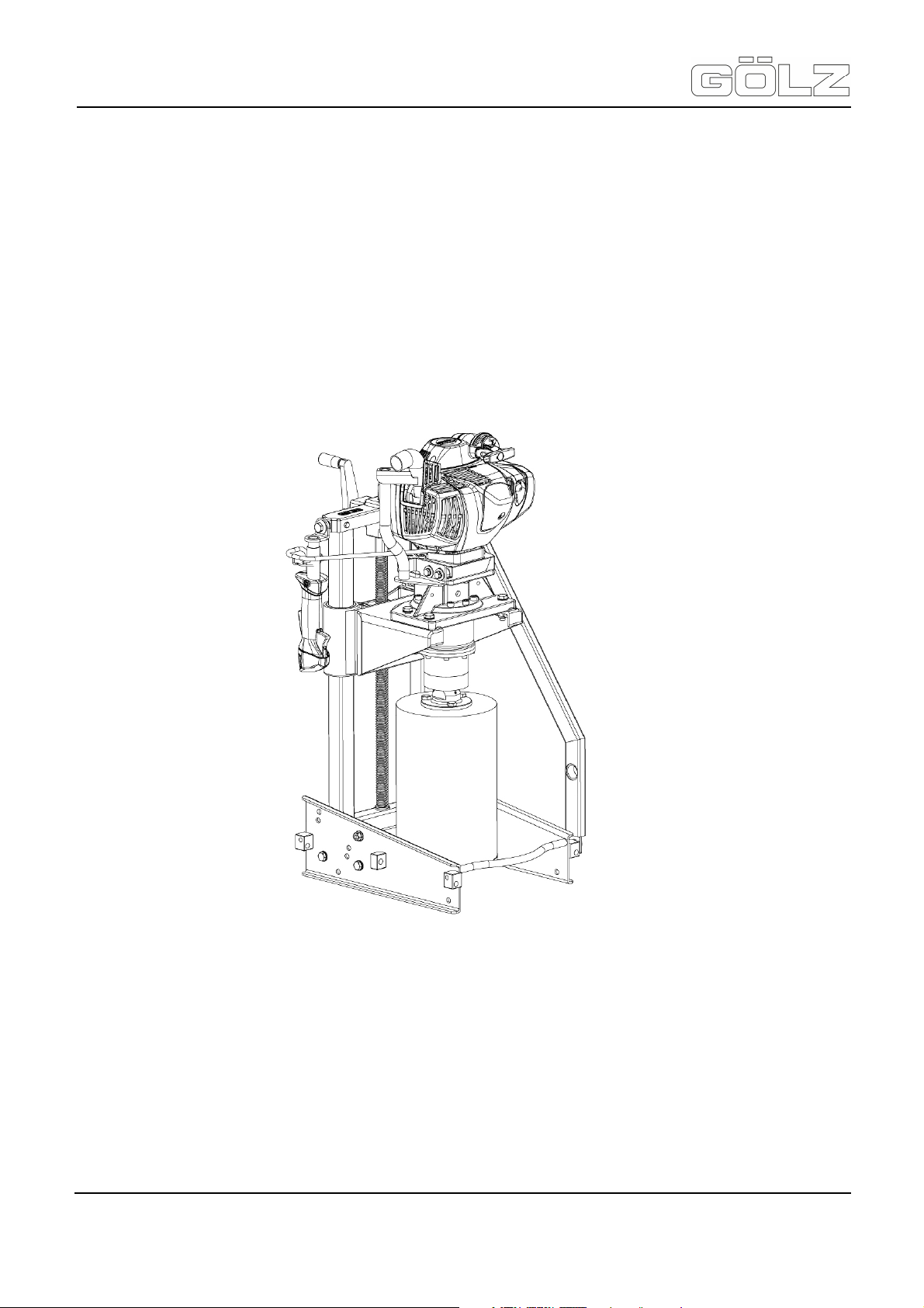
Drill rig
KB 300 - KB 350
with STIHL® Petrol-Engine
FS 560
ZN der Bedienungsanleitung: 5006892-01
Erstellt am: 05 / 2014
Erstellt von: Sabrina Linden
Datei: K:\KDV\5006xxx\5006892-Bedienungsanleitung\
5006892-01-Bedienungsanleitung-E.doc
GÖLZ® GmbH
Dommersbach 51
D-53940 Hellenthal
Telefon: +49 (0) 2482 12 200 / Telefax: +49 (0) 2482 12 222
E-Mail: info@goelz.de / Internet: www.goelz.de
®
- 1-
5006892-01
BA-E
Page 2

KB300 / KB350 with FS560
Translation of the original operating instruction and spare parts list
®
- 2-
5006892-01
BA-E
Page 3

KB300 / KB350 with FS560
shall not be liable for errors in this document (manual instruction and spare parts list) or for
Translation of the original operating instruction and spare parts list
All rights reserved according to DIN ISO 16016.
No part of this document (instruction manual and spare parts list) may be reproduced, adapted, transmitted,
transcribed, stored on a data medium or be translated into another language without prior written approval of
GÖLZ® GmbH
Dommersbach 51
D-53940 Hellenthal
Guarantee
We reserve the right to amend any information included in this document (manual instruction and spare parts
list) at any time and without prior notice.
GÖLZ® assumes no warranty for these documents.
®
GÖLZ
any collateral or consequential damage in connection with shipment, performance or use of the material.
®
- 3-
5006892-01
BA-E
Page 4

KB300 / KB350 with FS560
H. Schulte
Translation of the original operating instruction and spare parts list
EC-DECLARATION OF CONFORMITY
Manufacturer
GÖLZ® GmbH
Dommersbach 51, D-53940 Hellenthal
Tel.: (02482) 12 200 / Fax: (02482) 12 222
Declare hereby certifies on its sole responsibility that the following product:
KB 300 / KB 350
Drill rig
with
FS560
STIHL® Petrol-Engine
Serial number:____________________
which is explicitly referred to by this declaration meet the following directives:
2006/42/EG Safety and health requirement
2004/108/EG Electromagnetic compatibility
97/68/EG i.d.F. 2002/88/EG Exhaust emission directive
2000/14/EG Noise emission
meet the following standards:
EN 12100-1 / EN 12100-2, EN 12348:2000, EN 13309:2000, EN 61000, DIN EN ISO 3744-1995
Documented evidence conforming to the requirements of the directives is kept available for inspection at the
above manufacturer’s address.
Hellenthal, den 08.05.2014 ……………………………………….. ………………………………………..
General Manager
B. Schmitz
Chief of Design
®
- 4-
5006892-01
BA-E
Page 5

KB300 / KB350 with FS560
Translation of the original operating instruction and spare parts list
Contents
®
Preface ................................................................................................................................... 8
General description ............................................................................................................... 8
1.
Technical data and accessory ................................................................................... 9
1.1 Technical data of the machine .............................................................................................. 9
1.1.1
KB300 / KB350 .............................................................................................................................. 9
1.1.2
Motor STIHL® ................................................................................................................................. 9
1.2 Provided accessory ............................................................................................................ 10
1.3 Optional accessory ............................................................................................................. 10
2.
Description ................................................................................................................ 11
2.1 Main parts .......................................................................................................................... 11
2.2 Functional description ........................................................................................................ 11
3.
Basic safety instructions ......................................................................................... 13
3.1 Intended use ...................................................................................................................... 13
3.2 Operating range ................................................................................................................. 13
3.3 Organisational measures .................................................................................................... 14
3.4 Selection and qualification of person .................................................................................. 15
3.5 Safety instructions governing specific operational phases .................................................. 15
3.6 Special work related to the maintenance and repair of the machine ................................... 16
3.7 Information about special risks with electrical energy ......................................................... 17
3.8 Gas, dust, steam, smoke .................................................................................................... 17
3.9 Noise .................................................................................................................................. 17
3.10 Illumination ......................................................................................................................... 18
3.11 Oils, greases and other chemical substances ..................................................................... 18
3.12 Transport ............................................................................................................................ 18
3.13 Store .................................................................................................................................. 19
4.
Bringing into service ................................................................................................ 20
4.1 Export checking .................................................................................................................. 20
4.2 Petrol drill motor FS560 ...................................................................................................... 20
4.2.1
M-Tronic ....................................................................................................................................... 20
4.2.2
Fuel .............................................................................................................................................. 21
4.2.3
Air filter ......................................................................................................................................... 22
4.2.4
Winter operation .......................................................................................................................... 22
4.2.5
Spark plug .................................................................................................................................... 23
4.2.6
Adjusting the throttle cable .......................................................................................................... 23
4.3 Fixing the machine ............................................................................................................. 24
4.3.1
Placed on the ground secured by spikes..................................................................................... 24
4.3.2
By strap and ratchet at exposed pipe .......................................................................................... 25
4.3.3
Combination of ground spikes and strap ..................................................................................... 25
4.3.4
Fixing with dowels ........................................................................................................................ 26
4.3.5
Fixing with vacuum hold down ..................................................................................................... 26
4.3.6
Frame extension .......................................................................................................................... 27
4.4 Assembling a drill motor ..................................................................................................... 27
- 5-
5006892-01
BA-E
Page 6

KB300 / KB350 with FS560
Translation of the original operating instruction and spare parts list
4.4.1
Assembling a drill motor with gear box ........................................................................................ 27
4.4.2
Changing a drill motor with gear box ........................................................................................... 28
4.5 Water supply ...................................................................................................................... 28
4.5.1
With water tank-pressurzied type ................................................................................................ 28
4.5.2
Public water mains ....................................................................................................................... 29
4.6 Angle-drilling ...................................................................................................................... 29
4.7 Drill bit ................................................................................................................................ 30
4.7.1
With UNC-Adapter ....................................................................................................................... 30
4.7.2
With 3-hole flange ........................................................................................................................ 30
5.
Operation ................................................................................................................... 31
5.1 Before starting .................................................................................................................... 31
5.2 Starting the engine ............................................................................................................. 31
5.3 Operating instructions engine ............................................................................................. 33
5.4 Start drilling ........................................................................................................................ 33
5.5 Stop drilling ........................................................................................................................ 34
5.6 Changing the drill bit ........................................................................................................... 34
6.
Maintenance and care .............................................................................................. 35
6.1 Drill rig ................................................................................................................................ 35
6.2 Drill bit ................................................................................................................................ 35
6.3 Replacing the air filter ......................................................................................................... 35
6.4 Cleaning the air filter .......................................................................................................... 36
6.5 Changing the spark plug ..................................................................................................... 36
6.6 Replacing the starter rope and rewind spring ..................................................................... 37
6.7 Fuel pickup body in tank ..................................................................................................... 40
6.8 Spark arrestor in muffler and spacer................................................................................... 40
6.9 Maintenance and care engine ............................................................................................ 40
7.
Troubleshooting ....................................................................................................... 42
8.
Spare parts list .......................................................................................................... 44
8.1 Using the spare parts list .................................................................................................... 44
8.1.1
Safety regulation .......................................................................................................................... 44
8.1.2
Ordering information .................................................................................................................... 44
8.1.3
Distribution agencies ................................................................................................................... 45
8.2 Wearing parts ..................................................................................................................... 46
9.
Exploded view and spare parts list ......................................................................... 47
9.1 Drill rig ................................................................................................................................ 49
9.1.1
Drill rig KB300 .............................................................................................................................. 49
9.1.2
Drill rig KB350 .............................................................................................................................. 53
9.1.3
Carriage ....................................................................................................................................... 57
9.1.4
Crankcase .................................................................................................................................... 58
9.2 Gear box carrier ................................................................................................................. 59
9.3 Planetary gear .................................................................................................................... 60
9.4 Drive motor ......................................................................................................................... 61
9.5 Tool acceptance ................................................................................................................. 63
9.6 Motor .................................................................................................................................. 65
®
- 6-
5006892-01
BA-E
Page 7

KB300 / KB350 with FS560
Translation of the original operating instruction and spare parts list
9.6.1
Motor - Crankcase, Cylinder ........................................................................................................ 65
9.6.2
Motor - Rewind starter ................................................................................................................. 67
9.6.3
Motor - Muffler, Shroud ................................................................................................................ 69
9.6.4
Motor - Fuel tank .......................................................................................................................... 71
9.6.5
Motor - Spacer flange, Air filter, Filter housing ............................................................................ 73
9.6.6
Motor - Carburetor ....................................................................................................................... 75
9.6.7
Motor - Ignition system ................................................................................................................ 77
9.6.8
Motor - Clutch, Clutch housing .................................................................................................... 79
9.6.9
Motor - Handlebar ........................................................................................................................ 81
®
- 7-
5006892-01
BA-E
Page 8

KB300 / KB350 with FS560
Translation of the original operating instruction and spare parts list
Preface
This operating manual is designed to familiarize the user with drill rig, hereinafter referred to as the machine,
and to use its intended applications.
The operating manual contains important information on how to operate the machine safely, properly and most
efficiently. Observing these instructions helps to avoid danger, to reduce repair costs and downtimes and to
increase the reliability and the life of the machine.
This operating manual is to be supplemented by the respective national rules and regulations for accident
prevention and environmental protection.
The operating manual must always be available wherever the machine is in use.
It is to be read and applied by any person in charge of work with or on the machine, such as:
• Operation including setting up, troubleshooting in the course of work, elimination of manufacturing waste,
care and disposal of fuels and consumables.
• Servicing (maintenance, inspection, repair) and/or
• Transport
In addition to the operating manual and to the mandatory rules and regulations for accident prevention of the
country and place of use of the machine, the recognized technical rules for safe and proper working conditions
and procedures are also to be observed.
In this manual all the information required for the intended use of the unit is included. If though you have any
specific questions, please refer to your representative, to one of our sales representatives or directly to us:
GÖLZ® GmbH
Dommersbach 51, D-53940 Hellenthal
Telefon: +49 (0) 2482 12 200 / Telefax: +49 (0) 2482 12 222
E-Mail: info@goelz.de / Internet: www.goelz.de
General description
Wear safety glasses!
Wear hard hat!
Wear ear muffs!
®
Wear safety boots!
Wear protective gloves!
Never touch!
Danger exists to cut oneself!
Wear safety clothes!
Read owner’s manual
before first initiation!
General danger!
With water spraying forbidden!
- 8-
Wear dust protection!
Important advice!
Warning! Hot surface!
Risk of injuries !
5006892-01
BA-E
Page 9

KB300 / KB350 with FS560
Translation of the original operating instruction and spare parts list
1. Technical data and accessory
1.1 Technical data of the machine
1.1.1 KB300 / KB350
Type KB 300 KB 350
Stroke 450 - 17.7 450 - 17.7 mm - in.
Feed Manual Manual
Angle drilling up to 45° up to 45°
Weight 21 - 46.3 24 - 53 kg - lbs.
Weight with motor 41 - 90.4 44 - 97 kg - lbs.
Length 440 - 17.3 550 - 21.6 mm - in.
Breadth 340 - 13.4 410 - 16.1 mm - in.
Height 800 - 31.5 800 - 31.5 mm - in.
Drilling range
Ø 110 - Ø 290
Ø 4.4 - Ø 11.4
Ø 110 - Ø 354
Ø 4.4 - Ø 13.9
1.1.2 Motor STIHL®
Type FS560
mm - in.
®
Driving mechanism STIHL® - single cylinder - two-stroke-engine
Capacity 57,1 cm³
Cylinder bore 47 - 1.85 mm - in.
Piston stroke 32,9 - 1.3 mm - in.
Power 2,8 (3,8) kW (PS)
Max. operating speed of the spindle 100 / 300 / 600 RPM
Weight with drilling gear 20 - 44.1 kg - lbs.
Continuous sound level Lpeq 101 dB(A) according to ISO 22868
Sound power level Lweq 114 dB(A) according to ISO 22868
Vibration measurement a 3,3 m/s² according to ISO 22867
Ignition system (with electronic speed limit)
Principle Electronically controlled magneto
Spark plug
Electrode gap 0,5 - 0,02 mm - in.
Fuel system
Carburettor
Air filter Paper
(interference-suppressed)
NGK BPMR7A
Non position sensitive diaphragm carburettor with
integrated fuel pump
Fuel tank capacity 0,99 (990) L (cm³)
- 9-
5006892-01
BA-E
Page 10

KB300 / KB350 with FS560
Fine dust vacuum cleaner, dry vacuum cleaner, wet vacuum
Translation of the original operating instruction and spare parts list
Mixing ratio
with STIHL® 1:50 two-stroke engine oil 1:50 = 1 part oil + 50 parts petrol
®
with other branded two-stroke engine oils
classification TC
1:25 = 1 part oil + 25 parts petrol
1.2 Provided accessory
• Strap; 2,1 m, Clamping ratchet, Linch pin
• Ground spike
• Exhaust hose; 4 m
• Pressure tank 10l with hose
• 3-hole-flange or UNC-adapter
• Tool kit
• Wrench SW 17
• Wrench
• Operating instruction
• Spare parts list
1.3 Optional accessory
KB 300 KB 350
Work with electric motor
Work with pneumatic motor
Work with hydraulic motor
Suction plate kit (Suction of smooth pipes)
Vacuum pump C10
Base plate kit (sample coring)
Roller guide kit (base plates)
Frame extension (pipes < Ø 300)
Support (drill holes in the pipe Ø 1000 or more)
Dowel plate kit (dowels and screws)
Backhoe attachment kit
Sharpening plate (drill bits)
cleaner
For the item number of accessories, please refer to the current catalogue of GÖLZ®
If accessories are used which do not correspond to GÖLZ® specifications, no liability is assumed for any
damage resulting hereof.
For details regarding the selection of the right GÖLZ® diamond drill bits, please refer to the current GÖLZ
catalogue for diamond tools.
xxxx
®
- 10-
5006892-01
BA-E
Page 11
KB300 / KB350 with FS560
Translation of the original operating instruction and spare parts list
2. Description
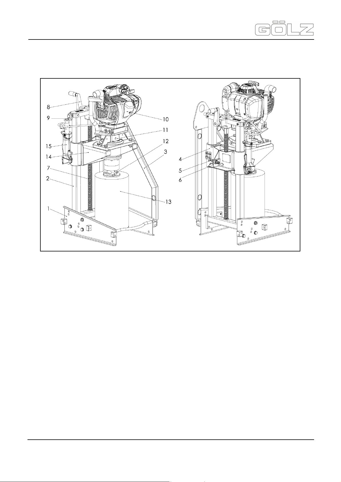
2.1 Main parts
2.2 Functional description
Due to its compact design and its lightweight construction, the KB300/350 unit with FS560 offers a practiceoriented use in a tight space. The proven STIHL®-Drive and the GÖLZ®-System-Technology ensure highest
operational safety and economic efficiency.
The KB300/350 with FS560 is used as a channel core drill for drills up to Ø 300 respectively Ø 350 mm for
manufacturing sewer pipes and manholes, for manufacturing new channels on the construction site as well as
for manufacturing later channel house connections.
Due to the fact that this unit is operated by the STIHL® FS560 gasoline-combustion engine the unit can be used
independently of power supply networks and irrespectively of its position.
To be able to operate this combustion engine also in a tight space, the supplied exhaust gas hose is fixed to the
motor so that exhaust gases can be discharged.
1) Pipe base 6) Water coupler 11) Planetary gear
2) Column 7) Spindle 12) 3-hole-flange
3) Floor frame with 8) Handle 13) Drill bit
lifting eye
4) Carriage 9) Control holder 14) Gear box carrier
5) Water tap 10) Petrol engine 15) Handlebar
®
- 11-
5006892-01
BA-E
Page 12

KB300 / KB350 with FS560
Translation of the original operating instruction and spare parts list
The exhaust of the motor as well as the exhaust gas hose were fitted with a protection against accidental
contact in order to avoid direct skin contact with hot surfaces.
The operating handle of the motor can be kept in the hand but also be positioned via the grip-adaption to the
unit.
On the gear box, either a drill bit flange or an adapter for the different tool sizes can be fitted. The
assembly of the tool is simple and easy. Regarding the flange the drill bit is fixed via a screw connection,
regarding the adapter via a threaded bolt.
The safe and easy assembly allows a quick exchange of the tools.
Water is supplied either via the supplied pressurized water container or via an external water connection. The
water hose of the pressurized water container is fitted via a coupling on the connection of the drill carriage. Thus
the water is directly routed via the gearbox into the drill bit and provides a sufficient cooling of the tool and binds
the cutting material.
The drill carriage moves on a double-guide column by means of a trapezoidal spindle. The trapezoidal spindle
allows an easy and smooth movement of the drill carriage on the column.
The drive is provided manually by default via the hand crank which can be fixed to the unit in two different ways.
Due to its special form, the pipe base can be set up with sewer junctions having different pipe diameters but
also at ground level. The base frame is fitted on the left by default, but can also be fitted on the right side. The
base frame provides the optimal support for working with the unit sidewise.
The KB300/350 offers the possibility of angle adjustment. Via the guide column, drill cuttings can be adjusted at
angles of 90°, 55° and 45°. This requires only a few screws to be loosened and the base frame to be rotated.
Due to its variable tension belt fastening or by using pegs, the unit can be used in different operative positions.
The wide range of accessories allows opening up additional working areas and additional drive systems.
Due to its compact design, the unit is easy to transport. The motor with gearbox can be easily and quickly
removed for transport. Via the crane eye which is attached to the base frame the KB300/350 with FS560 can
also be lifted with a crane.
The operator's station is behind the guide column or on the left or right next to it.
For working with this unit we recommend GÖLZ® diamond tools.
®
- 12-
5006892-01
BA-E
Page 13

KB300 / KB350 with FS560
Translation of the original operating instruction and spare parts list
3. Basic safety instructions
In this manual the following terms and symbols are used for particular important information:
Important text passages are highlighted in italics or bold or can be found in a grey highlighted text field.
3.1 Intended use
The machine has been built in accordance with state-of-the-art standards and the recognized safety rules.
Nevertheless, its use may constitute a risk to life and limb of the user or of third parties, or cause damage to the
machine and to other material property.
The machine must only be used in technical perfect condition in accordance with its designated use and the
instructions set out in the operating manual, and only by safety-conscious persons who are fully aware of the
risks involved in operating the machine. Any functional disorders, especially those affecting the safety of the
machine, should therefore be rectified immediately!
The machine is designed exclusively for drilling in concrete, reinforced concrete, natural stone, cast stone and
brickwork. Using the machine for purposes other than mentioned above (such as drilling in wood and so on) is
considered contrary to its designated use. The GÖLZ® GmbH cannot be held liable for any damage resulting
from such use. The risk of such misuse lies entirely with the user.
Only use gear drives and motors, which are provided by GÖLZ® GmbH. Also attend those operating manuals.
Operating the machine within the limits of its designated use also involves observing the instructions set out in
the operating manual and complying with the inspection and maintenance directives.
3.2 Operating range
The operating range of the unit can be extended due its wide range of accessories allowing easy retrofitting
which can be carried out by the operating personnel themselves.
Do not modify, add components to or retrofit the unit in a way which could affect its safety and do not use nonofficial accessories! This is not allowed without prior approval of GÖLZ® GmbH!
Note / Important: Contains important information which stands out from the other text!
Attention: Contains instructions which must be strictly observed to prevent damage from
the unit and the operator!
Attention: Read and observe all the operating instructions which belong to this unit!
Note: Read and observe the operating instructions to the accessories!
®
- 13-
5006892-01
BA-E
Page 14
KB300 / KB350 with FS560
Translation of the original operating instruction and spare parts list
3.3 Organisational measures
This operating manual must always be at hand at the place of use of the machine and must be accessible to the
person operating the machine!
In addition to this operating manual, all other generally applicable legal and other mandatory regulations
relevant to accident prevention and environmental protection must be observed! Such obligations may also
comprise the handling of hazardous materials, provisioning and/ or wearing of personal protective equipment, or
road traffic regulations.
This operating manual must be supplemented by instructions covering the duties involved in supervising and
notifying special organizational features, such as job organization, work flows or the person entrusted with the
work. Person entrusted with work on the machine must have read the operating manual prior to taking up work.
This applies especially to persons working only occasionally on the machine, e.g. during set-up or maintenance
activities.
Check - at least from time to time - whether the personnel is carrying out the work in compliance with the
operating manual and paying attention to risks and safety-relevant factors.
For reasons of safety, long hair must be tied back or otherwise secured, garments must be close-fitting and no
jewellery - including rings - may be worn.
Severe injury may result from being caught by moving parts of the machine. Personal protective equipment
must be used wherever required by the circumstances or by law (e.g. safety glasses, ear protectors, safety
boots, suitable safety clothing). Observe the regulations for prevention of accidents! Observe all safety
precautions and warnings attached to the machine and always keep them in good and perfectly legible
condition.
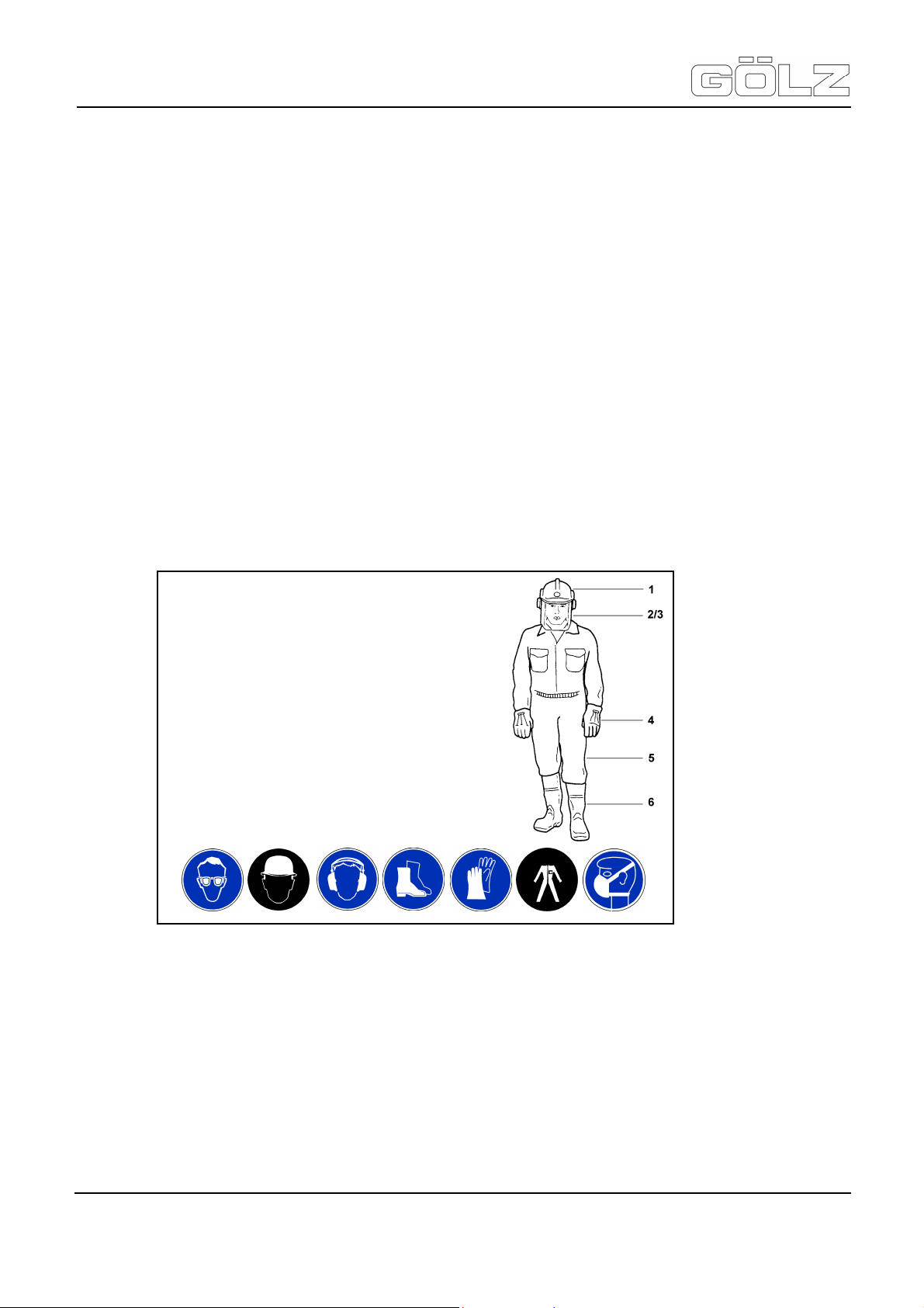
The personal protection equipment should consist of the following parts:
1) Hard hat with ear muff
2) Visor or safety glasses
3) Dust mask
4) Protective gloves
5) Safety clothes
6) Safety boots
®
In case event of safety-relevant modifications or changes in the behaviour of the machine, stop the machine
immediately and report the malfunction to the competent authority/ person. Do not remove or make inoperative
any safety devices the machine is equipped with.
Never make any modifications, additions or conversions which might affect safety without GÖLZ® GmbH prior
approval! This also applies to the installation and adjustment of safety devices as well as to welding and drilling
work on supporting structures.
Damaged or worn parts of the product must be replaced immediately. Use genuine spare parts only.
All spare parts and tools must comply with the technical requirements specified by the GÖLZ® GmbH. Adhere to
the legally prescribed preventive maintenance and inspection intervals or those specified in this operating
manual!
All maintenance and repair activities must be performed by qualified personnel using suitable tools and other
suitable workshop equipment.
- 14-
5006892-01
BA-E
Page 15

KB300 / KB350 with FS560
Translation of the original operating instruction and spare parts list
Observe the fire alarm and fire fighting measures. The personnel must be made familiar with the location and
handling of fire extinguishers!
3.4 Selection and qualification of person
Only permitted personnel is allowed to work on and with the machine! The legal minimum age is to be observed!
Only assign trained and instructed personnel! Clearly define the responsibilites of the personnel with regard to
operating, setting-up, maintaining and repairing the machine! The GÖLZ® GmbH can assist you in training your
personnel.
Make sure that only instructed and competent personnel works on the machine. Define the responsibility of the
machine operator, also in terms of traffic regulations and enable him to refuse instructions of third parties which
breach safety regulations.
Personnel that is to be trained or to be instructed or that is serving a general training is only to be permitted to
operate the machine under the supervision of an experienced person.
To operate the machine you must be rested, in good physical condition and mental health. If you have any
condition that might be aggravated by strenuous work, check with your doctor before operating with the
machine. Do not operate the machine if you are under the influence of any substance (drugs, alcohol) which
might impair vision, dexterity or judgment.
Works on electrical, pneumatic, combustion and hydraulic fittings and equipment are only to be carried out by
qualified personnel or instructed people being directed and supervised by qualified personnel in compliance with
the respective rules!
3.5 Safety instructions governing specific operational phases
Before work
Avoid any operational mode that might be prejudicial to safety!
Before beginning work, familiarize yourself with the surroundings and circumstances of the site, such as
obstacles in the working and travelling area, the soil bearing capacity and any barriers separating the
construction site from public roads.
Take the necessary precautions to ensure that the machine is used only when in a safe and reliable state.
Operate the machine only if all protective and safety-oriented devices, such as removable safety devices,
emergency shut-off equipment, sound-proofing elements and exhausters, are in place and fully functional.
Regard all safety specifications!
Check the machine at least once per working shift for obvious damage and defects. Report any changes (incl.
changes in the machine’s working behaviour) to the competent organization/ person immediately. If necessary,
stop the machine immediately and lock it. Have any defects rectified immediately.
At any time, ensure the operator has sufficient view to his working area, in order to have intervention to the
working process.
Wet drilling is to be accomplished while working. This prevents the appearance of particulate matter and
increases the life-time of the diamond tool.
During start-up and shut-down procedures always watch the indicators in accordance with the operating
instructions!
Before starting or setting the machine in motion, make sure that nobody is at risk. Keep children and
unauthorized persons away from the work area.
Noise protection equipment on the unit must be in protective position during operation. Wear the required
individual ear protection!
Attention: Persons with pacemakers only: The ignition system of your machine produces
an electromagnetic field of a very low intensity. This field may interfere with some
pacemakers. GÖLZ® recommends that persons with pacemakers consult their physician
and the pacemaker’s manufacturer to reduce any health risk.
®
- 15-
5006892-01
BA-E
Page 16

KB300 / KB350 with FS560
Translation of the original operating instruction and spare parts list
Always keep at a distance from the edges of building pits and slopes. Avoid any operation that might be a risk to
machine stability! Keep the work area clean. Cluttered areas and benches invite injuries! Do not operate when
you are tired! Watch what you are doing! Risk of stumpling! Cables and hoses must complete rolling up. After
assembly do not leave any tools, a wrench for example, on the unit.
Check to see that the tools are removed from the drill rig before operating! Damaged drill bits have to be
changed immediately. Use only recommended drill bits from the GÖLZ® GmbH.
Control the working area for water-, gas- and electrical lines!
During work
Make sure, that the drill rig is well fastened before and while drilling!
Never touch rotating parts like drill spindle or drill bit!
After work
Before leaving the machine always secure it against unauthorized use!
3.6 Special work related to the maintenance and repair of the machine
Observe the adjustment, maintenance and inspection activities and intervals set out in the operating
instructions, including information on the replacement of parts and equipment! These activities may be executed
by skilled personnel only. Brief operating personnel before beginning special operations or maintenance work,
and appoint a person to supervise the activities.
In any work concerning the operation, conversion or adjustment of the machine and it’s safety-oriented devices
or any work related to maintenance, inspection and repair, always observe the start-up and shut-down
procedures described in the operating instructions and the information on maintenance work. Ensure that the
maintenance area is adequately secured.
Carry out maintenance and repair work only of the machine is positioned on stable and level ground and has
been secured against inadvertent movement and buckling. If the machine is completely shut down for
maintenance and repair work, it must be secured against inadvertent starting.
To avoid the risk of accidents, individual parts and large assemblies being moved for replacement purposes
should be carefully attached to lifting tackle and secured. Use only suitable and technically perfect lifting gear
and suspension systems with adequate lifting capacity. Never work or stand under suspended loads.
The fastening of loads and the instructing of crane operators should be entrusted to experienced persons only.
The marshaller giving the instructions must be within sight or sound of the operator.
For carrying out overhead assembly work always use specially designed or otherwise safety-oriented ladders
and working platforms. Never use machine parts as a climbing aid. Wear safety harness when carrying out
maintenance work at greater heights.
Clean the machine, especially connections and threaded unions, of any traces of oil, fuel or preservatives
before carrying out maintenance / repair. Never use aggressive detergents. Use lint-free cleaning rags.
Before cleaning the machine with water, steam jet or detergents, cover or tape up all openings which -for safety
and functional reasons - must be protected against water, steam or detergent penetration.
Do not clean the machine with a high-pressure cleaner. The hard water jet can put damage to parts of the
machine. After cleaning, remove all covers and tapes applied for that purpose.
After cleaning check the machine for loose connections, chafe marks and damage! Have identified defects
repaired immediately!
Always tighten any screwed connections that have been loosened during maintenance and repair.
Any safety devices removed for set-up, maintenance or repair purposes must be refitted and checked
immediately upon completion of the maintenance and repair work. Ensure that all consumables and replaced
parts are disposed of safely and with minimum environmental impact.
Important: Wet drilling is to be accomplished while working! This prevents the appearance
of particulate matter and increases the life-time of the diamond tool!
Attention: Do not clean with high-pressure / splash water! Water / Dirt must not attain into
the exhaust system - engine damage!
®
- 16-
5006892-01
BA-E
Page 17

KB300 / KB350 with FS560
Translation of the original operating instruction and spare parts list
3.7 Information about special risks with electrical energy
Observe the relevant national regulations or standards. Electrical connections must always be kept free from dirt
and moisture.
Use only original fuses with the specified rating! Switch off the machine immediately, if trouble occurs in the
electric power supply!
If your machine comes into contact with a live wire:
• warn others against approaching and touching the machine
• have the live wire de-energized
When working with the machine, maintain a safe distance from overhead electric lines. If work is to be carried
out close to overhead lines, the working equipment must be kept well away from them. Caution, danger to life!
• Check out the prescribed safety distances.
• Work on the electrical system or equipment may only be carried out by a skilled electrician himself or by
specially instructed personnel under the control and supervision of such electrician and in accordance with
the applicable engineering rules.
• If provided for in the regulations, the power supply to parts of machines and plants, on which inspection,
maintenance and repair work is to be carried out must be cut off.
• Before starting work, check the de-energized parts for the presence of power and ground or short-circuit
them in addition to insulating adjacent live parts and elements.
The electrical equipment of machines is to be inspected and checked at regular intervals. Defects such as loose
connections or scorched cables must be rectified immediately.
Necessary work on live parts and elements must be carried out only in the presence of a second person who
can cut off the power supply in case of danger by actuating the emergency shut-off or main power switch.
Secure the working area with a red-and white safety chain and a warning sign. Use insulated tools only.
If mobile electrical equipment, connecting cables and/ or extension/ appliance cords with plug connectors are
used, ensure that such equipment, cables and cords are checked for correct function at least once every six
months by a qualified electrician or - if suitable testing equipment is available - by a properly instructed person.
Protective installations with fault-current protection units used in non-stationary equipment must be checked for
correct operation at least once a month by a properly instructed person.
Fault-current and fault-voltage protection units must be checked for correct operation by actuating the testing
facility:
• once on every working day in the case of mobile equipment,
• at least once every six months in the case of stationary equipment.
3.8 Gas, dust, steam, smoke
Operate combustion engines only in well-ventilated rooms! Before starting the unit in closed rooms, make sure
that the room is sufficiently ventilated and use the exhaust gas hose!
Welding, burning and grinding operations on the machine are only to be carried out if this is explicitly authorized
(there is the danger of fire and explosion)!
Before welding, burning and grinding operations clean the machine and its surrounding area from dust and
flammable substances and care for sufficient ventilation (danger of explosion)!
When working in confined spaces observe any existing national regulations!
3.9 Noise
During operation sound protection devices on the machine must be in safe position. Wear the prescribed
personal ear protection! (UVV 29 § 10, Article 29 of the Accident Prevention regulations).
The use of noise emitting machines may be restricted to certain times by national or local regulations.
®
- 17-
5006892-01
BA-E
Page 18

KB300 / KB350 with FS560
Translation of the original operating instruction and spare parts list
3.10 Illumination
The machine is designed for use in daylight! The machine operator / owner must ensure sufficient workplace
lighting for non-illuminated work sites!
3.11 Oils, greases and other chemical substances
When handling hydraulic fluids, lubricants, greases or preservatives (referred to hereinafter as fuels and
lubricants), the safety regulations which apply to the respective machine are to be observed!
Avoid long contact of the fuels and lubricants with your skin! Careful cleaning of the skin from adhering fuels and
lubricants is necessary.
Be careful when handling hot consumables (risk of burning or scalding) particularly at liquid temperatures above
60°C, avoid any skin contact with these liquids!
If you get fuels or lubricants in your eyes, rinse them immediately and carefully with potable water. Then consult
a doctor.
Remove flown out fuels and lubricants immediately! Therefore use a binder.
Fuels and lubricants must not seep into the soil or into the public sewage system! Fuels and lubricants which
can no longer be used are to be collected, properly stored and to be properly disposed of.
The respective regulations and laws for handling fuels and lubricants which are valid in the country of use are to
be observed and adhered to. This also applies to the disposal of such fuels and lubricants. To inform yourself
turn to the responsible authorities.
3.12 Transport
Use only suitable means of transport and lifting gear of sufficient capacity when loading or transporting the
machine! Appoint an experienced instructor for the lifting operation!
Always observe the instructions given in the operating manual when lifting the machine (use only the prescribed
lifting eyes for attaching the lifting gear)!
Use only suitable transport vehicles with sufficient load capacity! Secure the load carefully. Use suitable
fastening points for securing!
Before loading the machine or parts of it, secure the machine against inadvertent movement! Attach a suitable
warning sign!
The drill bit must be removed for transport. Even in case of a minor change of location, the engine must be
stopped!
Before using the machine again, make sure that such protection material or devices are properly removed!
Parts which had to be removed for transporting of the machine must be refitted and secured carefully before the
machine is used again!
Before setting the machine in motion always check that all accessories are safely stowed.
The recommissioning procedure must be strictly in accordance with the operating instruction! Observe the
instructions given in the operating instruction when reassembling and operating the machine.
Lifting eye
Attention: Check that all parts of the machine are well fastened
before transporting.
Before transport the drill bit must be removed!
For loading only, use lifting gear and tackle of sufficient capacity.
Lift the machine using the lifting eye.
- 18-
5006892-01
BA-E
®
Page 19

KB300 / KB350 with FS560
Translation of the original operating instruction and spare parts list
3.13 Store
Store the machine in a dry, high or locked place, out of the reach of children or unauthorized persons. Clean
and preserve the machine with corrosion preventive if storing over a longer time like winter time!
Note: store not mounted drill bits in a dry, high or locked place, out of the reach of children or unauthorized
persons!
Drill bits with a small diameter are only to be stored in a horizontal position, drill bits with a large diameter only in
a vertical position. Do not place any other parts or components on the drill bits.
®
- 19-
5006892-01
BA-E
Page 20
KB300 / KB350 with FS560
Translation of the original operating instruction and spare parts list
4. Bringing into service
4.1 Export checking
Remove the transport packaging and place the unit vertically on a horizontal, flat and stable surface.
Dispose of the transport packaging according to environmental regulations. Since the unit is delivered
completely assembled, you need only check if it is complete and intact.
For the scope of delivery, see "Technical Data and Accessories". In addition, check the travel path of the drill
carriage for proper movement.
4.2 Petrol drill motor FS560
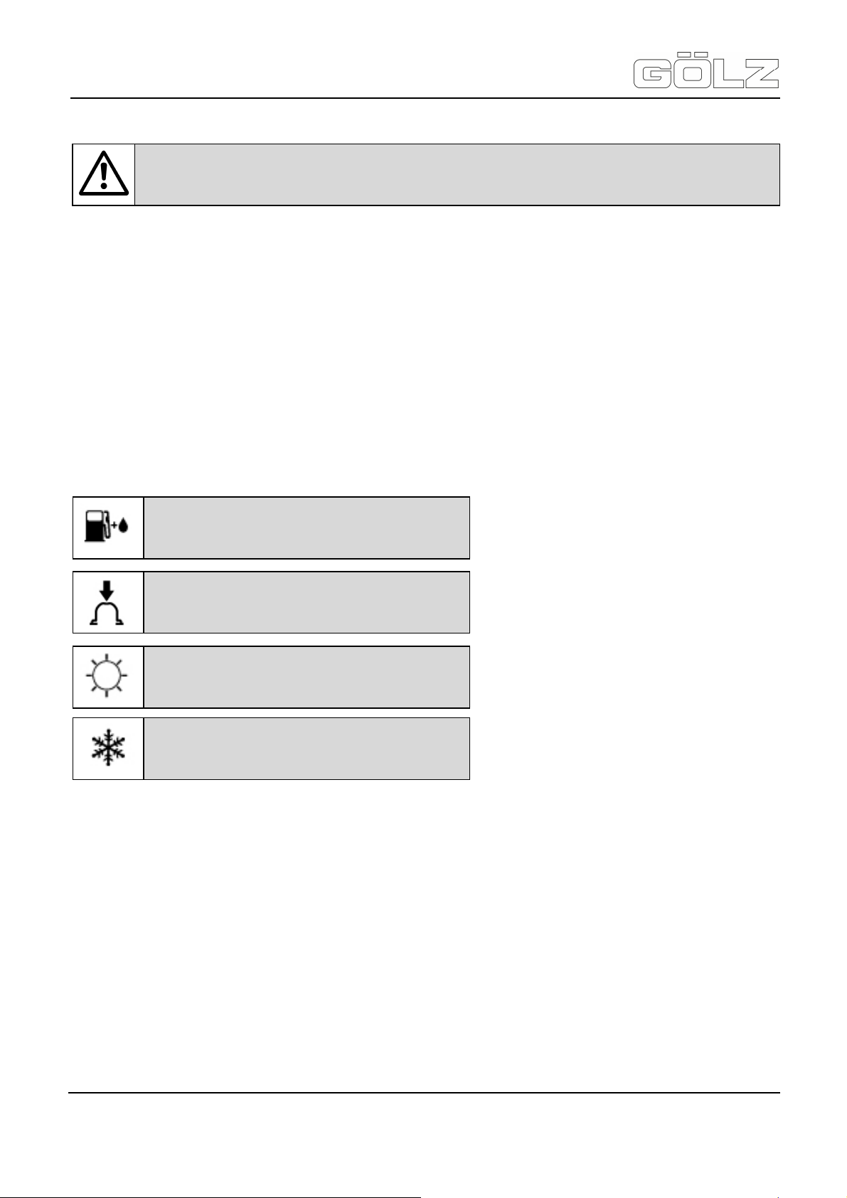
The meanings of the pictrograms attached to the machine:
4.2.1 M-Tronic
The M-Tronic controls fuel feed and ignition timing electronically in all operating conditions. M-Tronic guarantees
simple and fast starts. The engine is started in the Start ▲ position irrespective of climatic conditions or engine
temperature.
After starting, the Start ▲ position can be maintained until the engine runs smoothly. M-Tronic ensures optimum
engine power at all times, very good acceleration and automatic adjustment to suit changing conditions. For this
reason there is no need to change the carburetor setting - the carburetor has no adjusting screws.
If the usual good running behavior and engine power are not reached after an extreme change in operating
conditions, contact your servicing dealer for assistance. GÖLZ® recommends that you have servicing and repair
work carried out exclusively by an authorized GÖLZ® servicing dealer.
Attention: Do not yet turn the engine on! The following work is to be done with the drill
motor being stopped!
Fuel tank
Fuel mixture of gasoline and engine oil
Operate manual fuel pump
Intake air for summer operation
Intake air for winter operation
®
- 20-
5006892-01
BA-E
Page 21

KB300 / KB350 with FS560
Translation of the original operating instruction and spare parts list
4.2.2 Fuel
The engine requires a mixture of gasoline and engine oil. Unsuitable fuels or a mixing ratio that deviates from
the specification can lead to severe engine damage. The engine, seals, fuel lines and fuel tank may be
damaged if poor quality gasoline or engine oil is used. Use only high-quality gasoline with an octane rating of at
least 90 ROC - leaded or unleaded.
For reasons of health and for environmental reasons unleaded petrol is to be preferred. If fuel with an octane
number below 90 RON is used, glow ignition (causing "pinging" in the engine) and a rise of temperature may be
the result. This in turn can lead to damage to the driving mechanism on account of "piston jamming".
Mixing fuel
For preparing the fuel mixture only branded two-stroke engine oils are allowed! We particularly recommend the
STIHL-two-stroke engine oil 1:50; this oil is specifically blended for use in STIHL-engines. Mixing ratio: with
STIHL 1:50 two-stroke engine oil: 1:50, 1 part oil + 50 parts petrol, with other branded two-stroke engine oils
classification TC: 1:25, 1 part oil + 25 parts petrol.
When preparing the mixture, first fill in oil, then petrol.
Storing fuel mixture
Fuel mixture ages! Mix only as much as needed for a few weeks! Store in approved safety fuel canisters only in
a dry, cool and secure place protected against light and sunlight.
Do not store fuel mixture for longer than three months. The fuel mixture can become unusable faster if exposed
to light, sunlight or low or high temperatures. Fuel mixture that stagnates for a longer time unmixes. Therefore
shake the can containing the fuel mixture well before you fill it up again.
The fuel tank and the canister in which fuel mixture is stored should be cleaned thoroughly from time to time.
Residual fuel and the liquid used for cleaning must be disposed of in accordance with regulations and without
harming the environment!
Refuelling
Before refuelling stop the engine. Do not refuel as long as the engine is hot - fuel can overflow - fire hazard!
Open the fuel cap carefully so that overpressure is slowly reduced and no fuel spurts out.
Refuel only at well-ventilated places. If some fuel was spilled, immediately clean the motorized equipment - let
no fuel get in contact with your clothing, otherwise change your clothes immediately.
Thus the risk is reduced that the fuel cap unscrews on account of the vibration of the engine and fuel runs out.
Pay attention to leaks - if fuel runs out, do not start the engine - Danger to life on account of burns!
Attention: Avoid direct skin contact with and breathing in of gasoline fumes!
Attention: Pressure can build up insie the canister - open carefully!
Attention: Petrol is extremely flammable - keep it away from open fire - do not spill any fuel
- do not smoke!
Attention: After re-fuelling tighten the screw cap as tightly as possible.
- 21-
5006892-01
BA-E
®
Page 22
KB300 / KB350 with FS560
Translation of the original operating instruction and spare parts list
Filling up with fuel
Take care not to spill fuel while fueling and do not overfill the tank!
4.2.3 Air filter
The filter has a very long service life.
Dirty air filters reduce engine power, increase fuel consumption and make starting more difficult.
Replacing the air filter: Only if there is a noticeable loss of engine power!
4.2.4 Winter operation
At temperatures below +10°C
Preheating the carburettor. Repositioning a shutter allows heated air to be drawn in from around the cylinder
and mixed with cold air. This helps prevent carburettor icing.
Fuelling
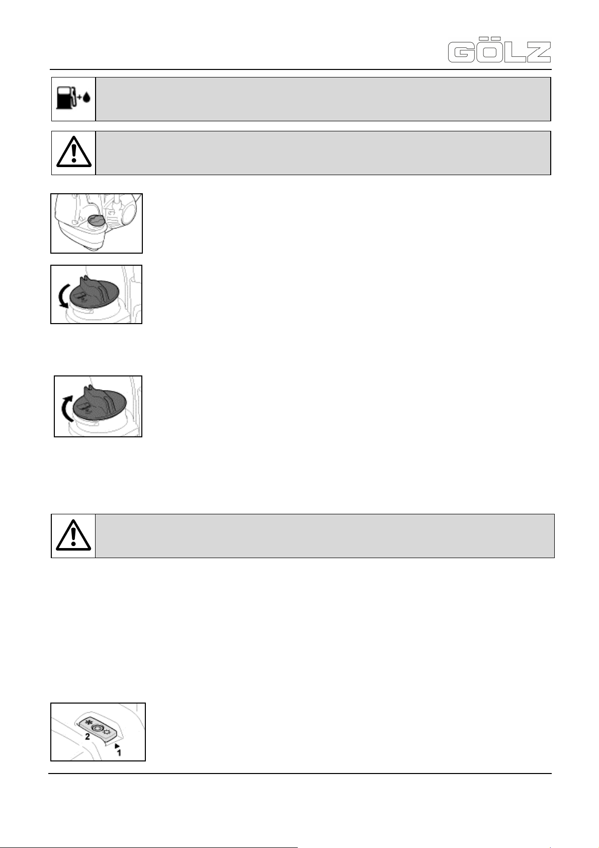
Attention: When fuelling on a slope, always position the machine with the filler cap facing
uphill!
Preparations
On level ground, position the machine so that the filler cap is facing up. Before fueling,
clean the filler cap and the area around it to ensure that no dirt falls into the tank.
Opening screw-type tank cap
Turn the cap counterclockwise until it can be removed from the tank opening.
Remove the cap.
Cosing screw-type tank cap
Place the cap in the opening.
Turn the cap clockwise as far as stop and tighten it down as firmly as possible by hand.
Attention: Do not remove the filter cover or replace the air filter as long as there is no
noticeable loss of power!
An arrow (Pos. 1) on the shroud indicates the setting of the shutter (Pos. 2) for summer
or winter operation.
Symbol sun = summer operation
Symbol snowflake = winter operation
- 22-
5006892-01
BA-E
®
Page 23
KB300 / KB350 with FS560
Translation of the original operating instruction and spare parts list
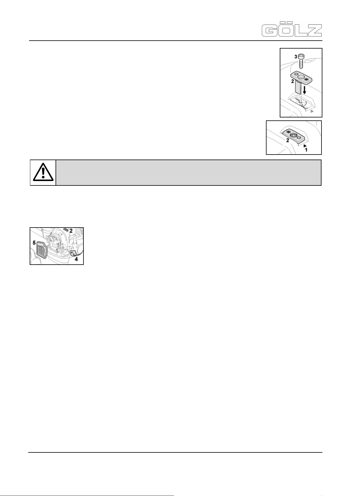
• Remove the screw (Pos. 3) from the shutter (Pos. 2).
• Pull the shutter (Pos. 2) out of the shroud.
• Rotate the shutter (Pos. 2) from the summer position to the winter position and refit it.
• Secure the shutter in position with the screw (Pos. 3).
At temperatures between +10°C and +20°C
The machine can normally be operated in this temperature range with the shutter (Pos. 2) in
the summer position. Change the position of the shutter if necessary.
At temperatuers above +20°C
Always return the shutter (Pos.2) to the summer position.
At temperatures below -10°C
In extreme wintry conditions:
• Temperatures below -10°C
• Powder or drifting snow
After installing the cover plate kit set the shutter (Pos. 2) to the winter position.
At temperatures above -10°C
Remove the parts of the cover plate kit and refit the standard parts for summer operation. Depending on the
ambient temperature set the shutter (Pos. 2) to the summer or winter position.
4.2.5 Spark plug
If the engine is down on power, difficult to start or runs poorly at idle speed, first check the spark plug. Fit a new
spark plug after about 100 operating hours or sooner if the electrodes are badly eroded. Install only suppressed
spark plugs of the type approved “specifications”.
4.2.6 Adjusting the throttle cable
Correct adjustment of the throttle cable is a precondition for correct operation of the machine in all modes, from
starting to full throttle. It may be necessary to readjust the throttle cable after assembling the machine or after a
prolonged period of operation.
Check the adjustment of throttle cable
The control handle must be in the normal operating position.
In the following adjustments do not produce the required result, have your servicing dealer repair the machine.
Attention: Do not operate the machine in the winter position at temperatures above +20°C
because there is otherwise a risk of engine running problems and overheating!
It is advisable to use the optional ”cover plate kit“.
The cover plate kit contains the following parts for converting the machine:
• Pos. 4: cover plate partially blanks off the slots in the starter housing.
• Pos. 5: Synthetic fabric filter element for the air filter.
- 23-
5006892-01
BA-E
®
Page 24
KB300 / KB350 with FS560
Translation of the original operating instruction and spare parts list
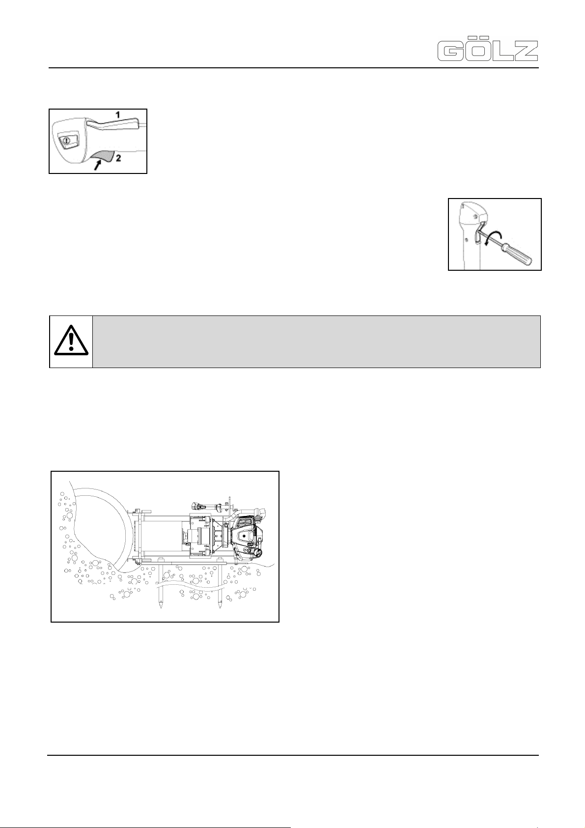
Error: Engine speed increases when only the throttle trigger is depressed.
• Starting the engine.
• Depress the throttle trigger (Pos. 2). Do not press down the throttle trigger lockout
(Pos. 1).
If the engine speed increases or if the cutting attachment rotates, the throttle cable has
to be adjusted.
• Stopping the engine
Adjusting the throttle cable
Depress the throttle trigger lockout (Pos. 1) and the throttles trigger (Pos. 2) as far as
stop and hold them in that position.
Apply only sufficient pressure to hold the levers against their stops.
• Rotate screw in throttle trigger ½ turn counter clockwise.
• Release the throttle trigger and throttle trigger lockout.
• Start the engine and check the adjustment.
• Shut down the engine and repeat adjustment if necessary.
Have the muffler checked by a servicing dealer for contamination!
4.3 Fixing the machine
4.3.1 Placed on the ground secured by spikes
Place the machine so that pipe base fits tight to the pipe. Back fill or remove material underneath the frame if
necessary.
The pipe base is centering the machine automatically. Secure the ground frame with minimum two ground
frame.
Attention: Attention: If engine running behaviour is still unsatisfactory after servicing the air
filter and adjusting the throttle cable, teh cause may be the muffler.
®
- 24-
5006892-01
BA-E
Page 25
KB300 / KB350 with FS560
Translation of the original operating instruction and spare parts list
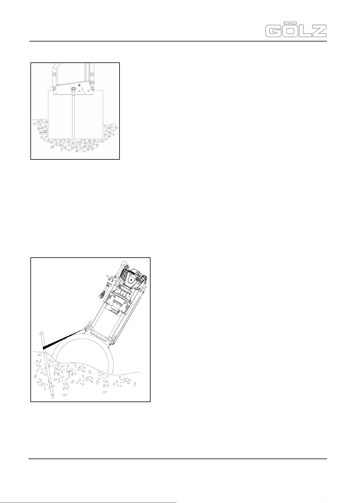
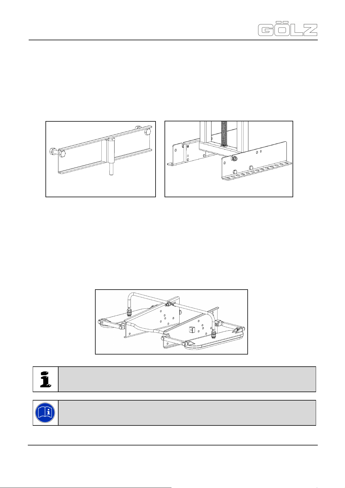
4.3.2 By strap and ratchet at exposed pipe
This application is only possible, if the pipe is completely exposed, so that the strap can be wrapped around the
pipe.
The end of the strap that has an „eye“ is attached to the holder by means of a shackle to the notch at the pipe
base. Attach the ratchet to the notch. Pull the strap through the split in the ratchet and stretch the strap by
moving the flap of the ratchet. Pull strap under the pipe. Do not twist the strap!
Releasing the ratchet: Pull up the pawl in the ratchet tensioner. Stretch the ratchet to the point the handle
engages.
4.3.3 Combination of ground spikes and strap
If the ground-condition at the drill-hole side are not convenient you can try a combination of Spikes and Strap as
follows:
• Hit one or two ground spikes on other side of pipe into the ground and wrap the strap around it (them) and
mount the shackle and the ratchet in the two outer notches on the pipe-base and stretch the strap.
• While drilling the operator’s weight should hold the machine down against the pipe. Reduced feed-pressure
should be obtained during this way of operation!
- 25-
5006892-01
BA-E
®
Page 26
KB300 / KB350 with FS560
Translation of the original operating instruction and spare parts list
4.3.4 Fixing with dowels
Set up of the machine on walls or flat surfaces one can choose two ways: Dowel plates or dowel base.
• Dowel plates are attached with bolts to the pipe base.
• Drill dowel holes, mount the dowel and set up the machine with bolts into the dowels. Please follow the
instructions of the dowel-producer!
• Use screws with a minimum length of 140 mm (51/2") when using dowel plates.
• Dowel base is consisting of 2 L-formed plates. The dowel base is attached into the holes of the pipe base,
so first the pipe-base has to be removed and then the two dowel base-plates are mounted instead of the
pipe base.
4.3.5 Fixing with vacuum hold down
• Remove the ground frame and place the machine with the pipe base onto the pipe.
• Attach the vacuum pads to the left and to the right of the pipe-frame, but do not tighten the bolts yet!
• Start the vacuum pump and wait until gauge on vacuum pump shows a minimum of 0,7 bar (10 PSi).
• Connect one male coupler of the vacuum system to one of the vacuum pads and wait until vacuum is built-
up.
• Repeat this operation to the second vacuum pad. Tighten all the bolts that connect the pads to pipe frame.
Fixing with dowel plates
Fixing with dowel base
Note: Vacuum is built up faster and safer if the pipe-surface is wetted with water before
attaching a pad.
Note: Read and observe the operating instructions to the vacuum suction plates!
®
- 26-
5006892-01
BA-E
Page 27

KB300 / KB350 with FS560
Translation of the original operating instruction and spare parts list
4.3.6 Frame extension
The frame extension is used to attach the machine on pipes less than 380mm (15 in.).
Fasten the frame extension with the added screws at the drill rig. Attach the drill rig as described with strap and
spikes.
®
Frame extension Ø 270 - 180 mm
Frame extension Ø 380 - 270 mm
4.4 Assembling a drill motor
4.4.1 Assembling a drill motor with gear box
The gear carrier is fitted to the drill carriage by default.
Place the motor via the gear box onto the gear carrier and screw the
components with four M10x45 screws, SW17, as well as eight washers
and four nuts.
Provide the water supply to the gear box. The water supply is ensured via a
plug connection between the gear carrier and the gear box.
Attention: The following work is to be done with the drill motor being stopped!
With the combustion engine FS560 you can attach the operating handle to the support of the
operating handle and secure with the clip splint.
- 27-
5006892-01
BA-E
Page 28

KB300 / KB350 with FS560
Translation of the original operating instruction and spare parts list
4.4.2 Changing a drill motor with gear box
Loosen the connection of the water supply to the gear box. The water supply
is ensured via a plug connection between the gear carrier and the gear box.
Loosen the plug connector on the gear box and pull out the water hose.
Loosen the four M10x45 screws, SW17, between the gear box and the
gear carrier.
Remove the four screws as well as the eight washers and the four nuts.
You can remove the drill motor with the gear box from the gear carrier.
With the combustion engine FS560 make sure that the operating handle
is no longer attached to the support of the operating handle.
Assembling a drill motor with gear box
Fit the new drill motor as described under „Assembling a drill motor with
gear box".
4.5 Water supply
The water supply at the interface ensures that the tool is cooled, the dust of the material is bound and the drill
hole is rinsed out.
4.5.1 With water tank-pressurzied type
New delivery: mount first the pressure-hose into the bottom-side-hole and tighten well.
Operation:
• Always make sure that there is no pressure left in the tank before you open the water-filling hole - so lift
• Depress pump-handle and turn handle left (anticlockwise).
• Fill approx. 10 litres (2.64 US gallons) but do not fill up completely. Put back hand pump and tighten
• Pump up a pressure of approx. 2 bar (29 PSI).
• During drilling a constant pressure of minimum 0,5 bar (7 PSI) is needed to guarantee a frequent water
Important: Wet drilling is to be accomplished while working! This prevents the appearance
of particulate matter and increases the life-time of the diamond tool!
Attention: Tools which are only designed for wet cutting, are never to be used without
water supply! Always ensure sufficient water supply!
Attention: For cutting only use water which is free from coarse impurities! Do not use salt
water!
red button on top-lock and release eventual existing pressure.
clockwise.
flow.
- 28-
5006892-01
BA-E
®
Page 29
KB300 / KB350 with FS560
Translation of the original operating instruction and spare parts list
Connection to core drilling machine
Connect Female Coupler on pressure hose to Male Nipple at the water-tap of the core drilling machine. The
water flow is increased or reduced by the water tap.
Release the female-coupler
The water hose is disconnected by pulling the outer sleeve of the female-coupler backwards and pulling off the
connection of the nipple
Safety regulations
Check periodically the pressure-relief-valve for proper function!
The maximum pressure is 6 bar (87 PSI). If the pressure is not released at max., pressure automatically, the
valve has to be replaced immediately. Any sort of damage on the tank (bottle) cracks or bumps, the bottle must
be changed and taken out of operation.
No repairs on the tank are permitted.
Do not expose the filled water tank to sun for a longer time, increased water temperature results in increased
internal pressure! Store water tank empty and protect against freezing!
4.5.2 Public water mains
Connect a 1/2" water hose to the water tap of the core drilling machine. The flow of water is to be regulated by
the tap.
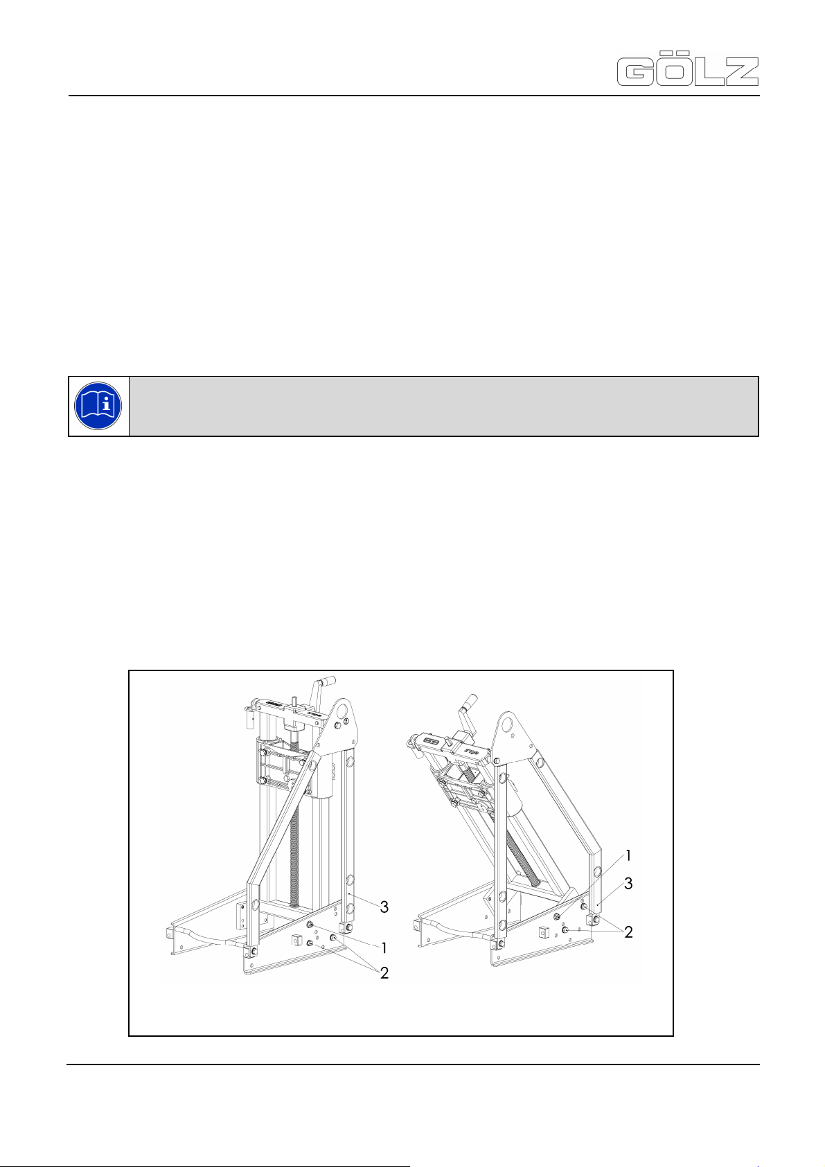
4.6 Angle-drilling
Upon delivery the unit is in the 90°-position. Do the angle adjustment as follows:
Note: Read and observe the operating instructions to the pressurized water container!
Ground frame in delivery position
90°-position
Ground frame turned 180° around
55°-position
®
- 29-
5006892-01
BA-E
Page 30

KB300 / KB350 with FS560
Translation of the original operating instruction and spare parts list
• Remove the bolts holding the ground frame (3) and remove frame
• Loosen the Nuts (1), left and right of pipe-base, but do not remove!
• Remove 4 Bolts (2) (2 on each side)
• Holding column, to base and tilt the column into required angle
• Secure 4 Bolts by hand
• Turn the ground-frame (3) around the other way and tighten bolts and nuts well.
4.7 Drill bit
The drill bits must meet the specifications of GÖLZ® GmbH. Use the appropriate bits depending on the material
to be processed, the working process and the type of work to be carried out! In case of non-intended use, no
liability is assumed for any damage resulting thereof.
All the bits which are used must, as far as their maximum admissible cutting speed is concerned, be designed
for the maximum drive speed of the unit. For units with a variable drive speed use drill bits which, as far as their
maximum admissible cutting speed is concerned, correspond to the respective drive speed. Ensure the right
rotational direction of the drill motor and of the drill bit!
Check the drill bits for proper fit. Defective drill bits must be immediately replaced!
Each time a drill bit is fitted or changed, the drill motor is to be stopped first. After assembly do not leave any
tools, a wrench for example, on the unit.
4.7.1 With UNC-Adapter
Fit the UNC-Adapter firmly to the gear box. Fit the adapter to the gearshaft in such a way that the serration
meshes and screw the two set screws in the adapter into the gearshaft.
Now wind the drill carriage up, but only to such point that the drill bit easily fits under the adapter.
When fitting the drill bit, please observe the following order:
• first the brass disc
• then the O-ring
• finally the drill bit
4.7.2 With 3-hole flange
Important: Before fitting the drill bit, carefully clean all the fastening elements!
Important: The connection threads must be clean!
Important: The connection flanges must be clean!
®
Fit the 3-hole flange to the gear box. Fit the flange to the gearshaft in such a way that the serration meshes and
screw the two set screws in the flange into the gearshaft. Now wind the drill carriage up, but only to such point
that the drill bit easily fits under the flange.
Then, with a wrench SW 17, screw the three screws M 10 x 20 through the flange into the holes of the drill bit.
Lock the flange with a SW 41 wrench.
- 30-
5006892-01
BA-E
Page 31
KB300 / KB350 with FS560
Translation of the original operating instruction and spare parts list
5. Operation
5.1 Before starting
Check that your machine is properly assembled and in good condition:
• All parts must be assembled properly and securely.
• The stop switch must move freely.
• Smooth action of choke knob, throttle trigger lockout and throttle trigger - the throttle trigger must return
• Check that the spark plug boot is secure - a loose boot may cause arcing that could ignite combustible
• Never attempt to modify the controls or safety devices in any way.
Do not operate your machine if it is damaged or not properly assembled!
Pay attention to the whereabouts of the cooling and rinsing water as well as of cutting slurries. Cutting slurries
must be collected, filtered and disposed of. Attach the unit according to the drilling problem. Move the drill bit
with the hand crank to 5mm to the drilling surface.
5.2 Starting the engine
Start the engine at least 3 meters from the fuelling spot. When work in closed or below
ground level it is absolutely necessary to use the exhaust hose!
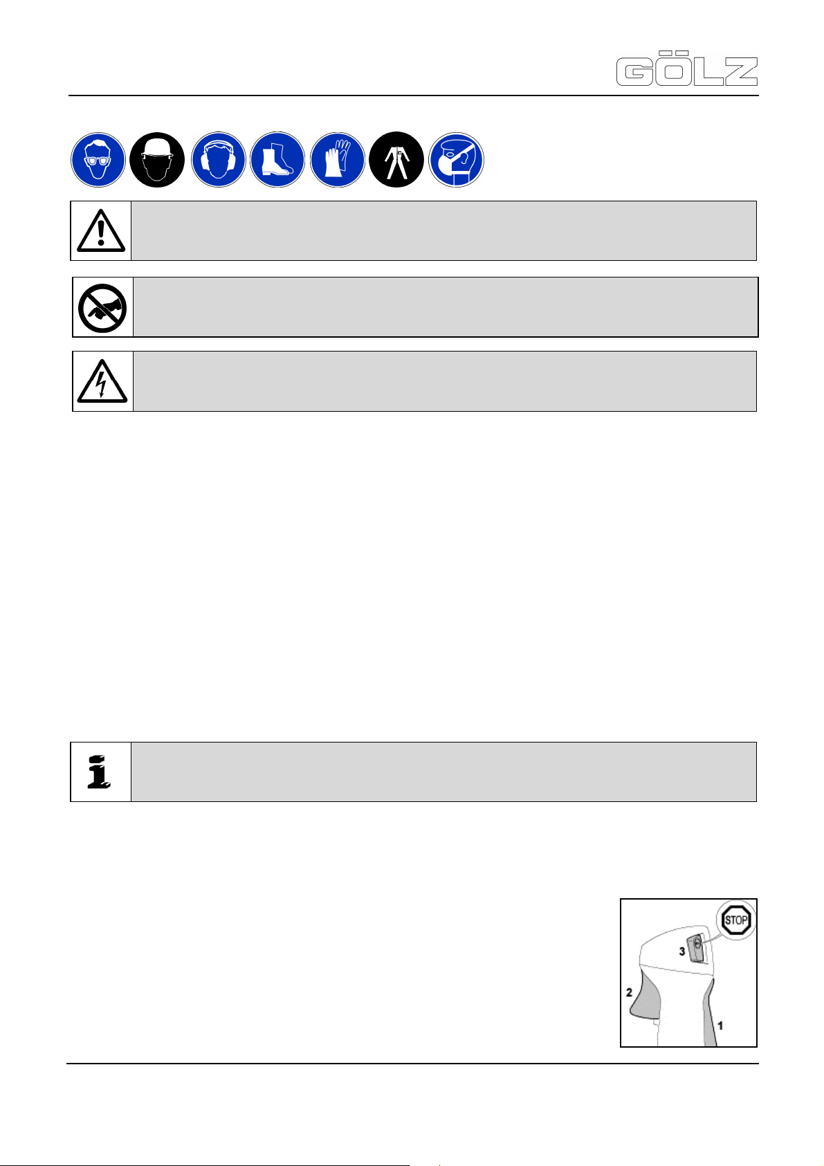
1. Throttle trigger lockout
2. Throttle trigger
3. Stop switch - with run and stop positions. Press the momentary contact stop switch
to switch off the ignition.
Attention: Make the site free of parts that might obstruct the operation! Make sure, the drill
bit is well mounted! Make sure, only authorized personnel is in the working area!
Warning: Never touch rotating parts like drill spindle and drill bit!
Attention: Make sure, that there are no mains in the material and location of the hole to be
drilled!
automatically to the idle position. The choke knob must spring back from the ▲ position to the run position I
when the throttle trigger lockout and throttle trigger are squeezed.
fumes and cause a fire!
Important: Fit the exhaust gas hose when working in closed rooms or below ground level!
- 31-
5006892-01
BA-E
®
Page 32

KB300 / KB350 with FS560
Translation of the original operating instruction and spare parts list
Function of stop switch and ignition system
The stop switch is normally in the run position: Ignition is on in this position - the engine is ready to start and
may be started. The ignition is switched off when the stop switch is depressed. It is automatically switched on
again after the engine comes to a standstill.
Symbols on choke knob
• Start ▲: the engine is started in this position.
• Normal run position I : engine runs or can fire.
Start the engine
• Press the fuel pump bulb (Pos. 4) at least five times. Even if the bulb is filled with fuel.
• Depress in the outer edge (arrows) of the choke knob (Pos. 5) and then turn it to start
▲.
• Hold the starter grip with your hand.
• Do not pull out the starter rope all the way - it might otherwise break!
• Do not let the starter grip snap back. Guide it slowly back into the housing so that the
starter rope can rewind properly.
• Continue cranking until the engine runs.
As soon as the engine runs: Make sure the engine runs smoothly.
If the engine stalls: continue cranking until the engine runs.
As soon as the engine runs smoothly
After a cold start, allow the engine to warm up in the start ▲ position.
If you have started the machine for the first time, refer to the notes on “starting for first time”.
• Depress throttle trigger lockout and pull the throttle trigger - the choke knob moves
to the run I position.
If the spindle rotates when the engine is idling, refer to notes in chapter “adjusting the throttle cable” or have the
machine serviced by your dealer.
Starting for first time
Attention: The spindle must not rotate in the run I position with the engine at idling speed!
• Depress the throttle trigger - do not press down the throttle trigger lockout.
If engine speed increases or the cutting attachment rotates:
• Go to section “stopping the engine“.
• Go to chapter ”adjusting the throttle cable“.
If the engine speed does not increase, your machine is ready for operation.
®
- 32-
5006892-01
BA-E
Page 33

KB300 / KB350 with FS560
Translation of the original operating instruction and spare parts list
At very low outside temperatures
• Set the engine to winter operation if necessary.
• If the machine is very cold (frost on machine), allow the engine to warm up in the start ▲ position after
starting until normal operating temperature is reached. Warning: the spindle rotates in this position!
At very high outside temperatures
• If the engine does not start after 10 pulls in the start ▲ position:
• Start the engine in the run I position.
If the engine does not start
• Check that all settings are correct.
• Check that there is fuel in the tank and refuel if necessary.
• Check that the spark plug boot is properly connected.
• Repeat the starting procedure.
Fuel tank runs until completely dry
• After refuelling, press the fuel pump bulb at least five times. Even if the bulb is filled with fuel.
• Start the engine.
5.3 Operating instructions engine
During break-in period
A factory-new machine should not be run at high revs (full throttle off load) for the first three tank fillings. This
avoids unnecessary high loads during the break-in period. As all moving parts have to bed in during the break-in
period, the frictional resistances in the engine are greater during this period. The engine develops its maximum
power after about 5 to 15 tank fillings.
During operation
After a long period of full throttle operation, allow the engine to run for a short while at idle speed so that engine
heat can be dissipated by the flow of cooling air. This protects engine-mounted components (ignition,
carburettor) from thermal overload.
After finishing work
Storing for a short period: Wait for the engine to cools down. Empty the fuel tank and keep the machine in a dry
place, well away from sources of ignition, until you need it again.
• For longer out-of-service periods: For periods of 3 months or longer:
• Drain and clean the fuel tank in a well-ventilated area.
• Dispose of fuel properly in accordance with local environmental requirements.
• Run the engine until the carburettor is dry. This helps prevent the carburettor diaphragms sticking together!
• Remove, clean and inspect the machine!
• Store the machine in a dry and secure location - out of the reach of children and other unauthorized
persons.
5.4 Start drilling
Important: Observe all the previous chapters in this manual, in particular the safety and
warning instructions!
Warning: Never touch rotating parts like drill spindle and drill bit!
®
- 33-
5006892-01
BA-E
Page 34

KB300 / KB350 with FS560
Translation of the original operating instruction and spare parts list
Care for safety clearance regarding third persons and take the operator's station behind the unit or slightly right
or left of it.
First provide the water supply as described in the chapter "water supply". The drill bit is about 5mm above the
material which is to be drilled. Then start the motor as described in the chapter "Start the motor". When you start
drilling first use a moderate feed pressure - turn the hand crank slowly to make the first cut.
After start of drilling you should care for an even drill feed (drill bit pressure). The drill feed must be adapted to
the material to be drilled!
5.5 Stop drilling
When winding the crank in the opposite direction, you move the drill bit out of the drill section. As soon as the
drill bit has left the section, stop the motor.
Stopping the engine
Next, block the water supply. If no further drilling is done, the drill bit is to be removed. Carry out the
maintenance and care work according to the chapter "maintenance and care".
5.6 Changing the drill bit
The drill bit is changed if:
• the diamond segments of the drill bit are completely worn
• the material to be cut changes
• the drill bit turns irregularly
• the diamond segments are damaged or broken
For fitting a new drill bit, proceed as described in the chapter 4.7 "drill bits".
Attention: Transport the unit only when the engine is stopped! This applies also to a short
change of location!
Attention: Wear appropriate individual protective equipment!
Feed too high - Motor overload!
Feed too low - Blunt segments!
• Depress the momentary contact stop switch.
• The engine stops.
• Release the stop switch.
• The stop switch springs back to the run position.
®
- 34-
5006892-01
BA-E
Page 35

KB300 / KB350 with FS560
Before starting
Visual inspection
Translation of the original operating instruction and spare parts list
6. Maintenance and care
Spare parts must comply with the technical requirements specified by the manufacturer. Spare parts from
GÖLZ® can be relied to do so! Observe the following indications:
In accordance to the given cycles, the subsequently described maintenance work has to be enforced. Also the
wearing parts subject to no certain maintenance-intervals have to be checked regularly for wear and to adjust if
necessary or to exchange. With I.C. engines, the maintenance work has to be enforced in accordance with the
separate maintenance-instruction of the engine manufacturer.
Machine
Attention: All maintenance, repair and care work is only to be done with the motor being
stopped!
In the event of
a malfunction
x x
If damaged
work
Clean
x
After work Weekly
x
®
Threaded spindle Grease
Column
Drill bit
Spray with sliding
spray
Check
Clean thread
Repair
x x
x
x
x
x
x
6.1 Drill rig
Clean the machine and also the carriage well after each duty and check all functions. Replace all necessary
parts that are out of order or worn out immediately. Spray in the column with commercial sliding spray.
6.2 Drill bit
When ending a drill job - check drill bit as follows:
Check segments for cracks or break-outs, Cracks between segment and core barrel, Deformation and
out of round wear.
In case of doubt, send the drill bit for repair (retip). Blunt drill bits should be re-sharpened.
6.3 Replacing the air filter
Important: Only if there is a noticeable loss of engine power!
• Set the choke knob to ▲.
• Loosen the screws (Pos. 1).
- 35-
5006892-01
BA-E
Page 36

KB300 / KB350 with FS560
Translation of the original operating instruction and spare parts list
• Remove the filter cover (Pos. 2).
• Clean away loose dirt from around the filter (Pos. 3) and inside the filter cover.
The air filter (Pos. 3) is a pleated paper filter element.
• Remove and check the filter element (Pos. 3) and replace if paper or frame is dirty or damaged.
• Unpack the new filter.
Do not bend or twist the filter before installation as it might otherwise be damaged. Do not use damaged filters!
• Fit the filter in the filter housing and fit the filter cover
Use only high quality air filters to ensure the engine is protected from abrasive dust. We recommend you use
only original STIHL® air filters. The high quality standard of these parts guarantees trouble-free operation, a long
engine life and very long filter service life. Maintenance and care of the special filter element for winter operation
are described in the chapter on “winter operation”.
6.4 Cleaning the air filter
• Loosen filter cover mounting screws.
• Remove the filter cover (Pos. 5).
• Clean away loose dirt from around the filter (Pos. 5) and inside the filter cover.
• Knock the filter (Pos. 5) out on the palm of your hand or blow it clear with
compressed air from the inside outwards.
In case of stubborn dirt or sticky filter fabric:
Wash the filter in a clean, non-flammable solution (e.g. warm soapy water) and then dry. Always replace a
damaged filter!
6.5 Changing the spark plug
Removing the spark plug
• Rotate the screw (Pos. 1) in the cap (Pos. 2) until the screw head projects from it.
®
• Lift the front of the cap (Pos. 2) and push it to the rear to disengage.
• Put the cap to one side.
• Remove the spark plug boot (Pos. 3).
• Unscrew the spark plug.
Checking the spark pug
• Clean dirty spark plug
• Check electrode gap A and readjust if necessary. See „specifications“.
• Rectify the problems which have caused fouling of the spark plug.
Possible causes are:
• too much oil in fuel mix,
• dirty air filter,
• unfavourable running conditions.
- 36-
5006892-01
BA-E
Page 37

KB300 / KB350 with FS560
Translation of the original operating instruction and spare parts list
Installing the spark plug
6.6 Replacing the starter rope and rewind spring
Replacing the starter rope and rewind spring
If either the starter rope or rewind spring is broken, continue with “removing the rope rotor”. If either the starter
rope or rewind spring are being replaced as a precautionary measure, continue with the following chapter.
Releasing tension on rewind spring
Use the tensioning wrench (Pos. 6). It is available as a special accessory.
• Use starter grip to pull out the starter rope as far as stop.
• Hold the tensioning wrench and the starter mechanism steady so that the rope
• Grip the rope inside the housing, pull it out to its full length and make a loop.
• Allow tensioning wrench to rotate slowly and thus release spring tension. The
• Remove the tensioning wrench from the carrier.
Attention: If the spark plug comes with a detachable adapter nut (Pos. 1) screw the adapter
onto the thread and tighten it down firmly to reduce the risk of arcing and fire!
• Screw the spark plug into the cylinder.
• Press the spark plug boot firmly onto the spark plug
• Fit the cap on the shroud from the rear and push the lug (Pos. 2) into the
opening (Pos. 3) in the shroud at the same time.
• Swing the cap forwards onto the shroud, insert and tighten down the screw
firmly.
• Take out the screws (Pos. 1).
• Lift away the rewind starter.
• If necessary, swing the pawls (Pos. 2) inwards.
• Rotate the spring clip (Pos. 3) out of the recesses (Pos. 4) in the carrier (Pos. 5).
• Position the tensioning wrench in the carrier so that the peg (Pos. 6) engages one of
the recesses (Pos. 4).
does not rewind onto the rope rotor.
rope winds itself around the tensioning wrench in this process until the spring is
no longer under tension.
®
- 37-
5006892-01
BA-E
Page 38
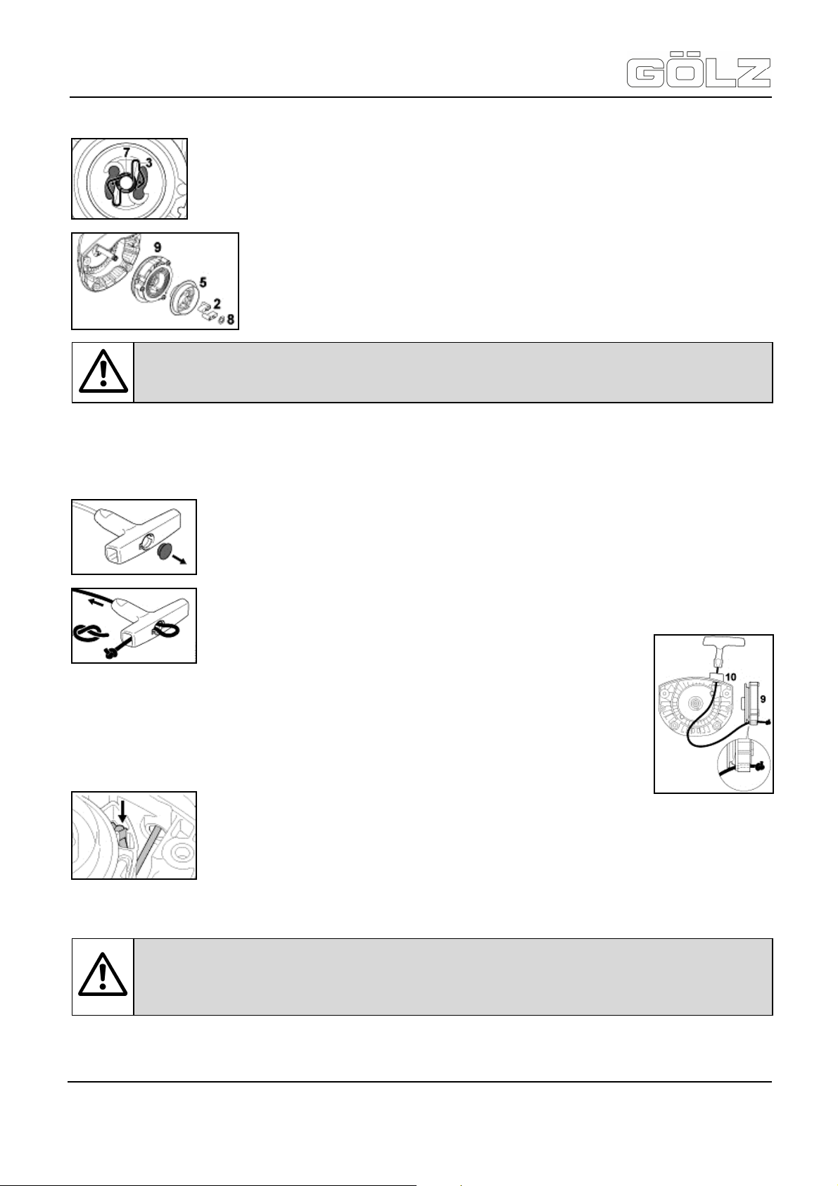
KB300 / KB350 with FS560
Translation of the original operating instruction and spare parts list
Removing the rope rotor
• Use a screwdriver or suitable pliers to remove the spring clip (Pos. 3) from the starter
post.
• Carefully remove the E-clip (Pos. 7).
• Carefully remove the carrier (Pos. 5) with pawls (Pos. 2) and washer (Pos. 8)
and put them to one side so that the pawls and washer cannot fall out.
• Pull the rope rotor (Pos. 9) off the starter post.
If the rewind spring needs to be replaced, continue with “replacing the rewind spring”. If the starter rope needs
to be replaced, continue with the following chapter.
Replacing the starter rope
• Thread the rope through the top of the guide bushing (Pos. 10) and rope rotor (Pos.
9).
• Tie a simple overhand knot in the end of the rope.
Attention: The pressure spring may pop out and uncoil during this operation. Take care to
avoid the risk of injury!
• Pry the cap out of the starter grip.
• Remove worn rope or remaining rope from the rotor and starter grip.
• Thread the new rope through the starter grip and tie a simple overhand knot in its
end as shown.
• Pull the knot back into the grip.
• Refit the cap in the grip.
®
• Pull the knot into the rope rotor. If necessary, push the knot into the rotor’s recess.
Go to “installing the rope rotor”.
Replacing the rewind spring
Attention: The bits of the spring may still be under tension and could fly apart when you
remove the rope rotor and spring housing. To reduce the risk of injury, wear face protection
and work gloves!
- 38-
5006892-01
BA-E
Page 39

KB300 / KB350 with FS560
Translation of the original operating instruction and spare parts list
• Take out the screws (Pos. 11).
• Remove the spring housing and spring or bits of the spring.
• Lubricate the new, ready-to-fit replacement spring in the new spring housing with a
few drops of resin-free oil.
• Fit the replacement spring with spring housing - the bottom plate must face up.
• Fit the screws.
Installing the rope rotor
• Coat the whole starter post uniformly - including the grooves (arrow) - with gear lubricant (special
assessor).
• Slip the rotor over the starter post - turn it back and forth to engage the anchor
loop of the rewind spring.
• Slip the carrier with pawls and washer over the starter post - turn it back and
forth to engage the anchor loop of the rewind spring in the carrier.
Attention: If the spring pops out of the housing during installation: wear face protection and
work gloves and refit the spring in the spring housing - clockwise - from the outside
inwards!
®
• Fit the E-clip (Pos. 7) in the grooves in the starter post.
• Push the spring clip (Pos. 3) into position - it must point counter clockwise as shown
and engage the pawls peg.
Tensioning the rewind spring
• Pull the starter rope out of the housing as far as stop and make a loop.
• Fit the tensioning wrench on the carrier.
• Use the tensioning wrench to rotate the rotor six
full turns counter clockwise - the rope winds itself around the tensioning
wrench in this process.
• Hold the tensioning wrench steady and unwind the rope.
• Pull out and straighten the twisted rope at the starter grip.
• Hold the rope steady with the starter grip.
• Release the tensioning wrench and rope slowly so that it winds onto the rotor.
• Remove the tensioning wrench.
The starter grip must locate firmly in the guide bushing. If the grip droops to one side: add one more turn on the
rope rotor to increase spring tension.
- 39-
5006892-01
BA-E
Page 40

KB300 / KB350 with FS560
Translation of the original operating instruction and spare parts list
• Take one turn of the rope off the rotor.
Installing the rewind starter
6.7 Fuel pickup body in tank
6.8 Spark arrestor in muffler and spacer
• The spark arrestor is country-specific.
• If the engine power decreases, check the spark arrestor in the silencer.
6.9 Maintenance and care engine
The following intervals apply to normal operating conditions only. If your daily working time is longer or operating
conditions are difficult (very dusty work area, etc.) shorten the specified intervals accordingly.
Attention: When the starter rope is fully extended it must still be possible to rotate the rotor
at least one more turn. If this is not the case, the spring is overtensioned and could break!
• Position and line up the rewind starter on the engine
• Insert the screws (Pos. 1) and tighten them down firmly.
• Check the pickup body in the fuel tank every year and have it replaced if
necessary.
The pickup body should be positioned in the area of the tank shown in the illustration.
®
Visual inspection (condition,
leaks)
Complete machine
Control handle Check operation
Air filter, paper filter Visual inspection
clean
Replace any damaged parts
X X
X
X
X X
X X
- 40-
5006892-01
BA-E
Page 41

KB300 / KB350 with FS560
Translation of the original operating instruction and spare parts list
®
Air filter, paper filter replace 1)
Visual inspection
Air filter, synthetic fabric
filter
clean
replace
Fuel tank clean
check 2)
Pickup body in fuel tank
replace 2)
Check - the spindle / the tool
Engine idle speed
must not turn
If the tool turns when the
engine is idling, have machine
repaired by servicing dealer
Readjust electrode gap
Spark plug
Replace after every 100
operating hours
Visual inspection
Cooling inlets
clean
X
X X
X
X X
X
X
X X X
X X
X
X
X
X
Cylinder fins clean 2)
Spark arrestor3) in
muffler
All accessible screws
and nuts 4)
check 2)
clean or replace
retighten
Visual inspection
X
X
X
X
X X
Antivibration elements
X
X X
X
X X
Tool
replace 2)
Visual inspection
replace
Check tightness
Decoke after first 139 hours of
Exhaust port
operation, then every 150
X
hours of operation
Safety labels replace
1)
Only if there is a noticeable loss of engine power
2)
by servicing dealer
3)
country-specific
4)
tighten down the muffler mounting screws firmly after first 10 to 20 hours of operation
X
- 41-
5006892-01
BA-E
Page 42

KB300 / KB350 with FS560
Translation of the original operating instruction and spare parts list
7. Troubleshooting
Cause Remedy
Blunt drill bit
®
Hard bonded segment!
Segment too big surface
Too fast RPM!
Drilling in steel!
Drill bit worn out!
Diamond grains pressed into the binding!
Segment surface is daubed with material sludge
Segment surface is daubed with steel chips
No free cut because of side wards wear-out of
segments!
Use segments one class softer bonded
Attach a drill bit with less segments or reduce the rpm
an increase the feed compression.
Use lower RPM.
Use lower gear and reduce feed and increase water
flow.
Replace with a new one.
Sharpen drill bit in sharpening plate, work with low feed.
Increase the water flow, re-sharp the segments
Reduce the speed, increase the water flow, re-sharp
the segments
Replace the drill bit and have the drill motor spindle
checked.
Soft bonded segments!
Segments to narrow!
Too low RPM!
Drill bit is deformed!
Drill bit out of true!
Abrasive material!
Water supply low!
Excessive wear of segments
Use segments one class harder bonded or increase
rpm and reduce the feed compression
Use drill bit with wider segments or reduce feed.
Shift the higher gear.
Change drill bit for a new one and bring worn drill bit for
rebalancing. Check drill stem and adjust or replace it.
Do not use deformed drill bits - it is also wearing out the
drill motor.
Change drill bit and bring worn drill bit for re-balancing.
Use segments one class harder bonded. Increase the
water flow and the speed.
Water supply raising.
- 42-
5006892-01
BA-E
Page 43

KB300 / KB350 with FS560
Translation of the original operating instruction and spare parts list
Cause Remedy
Drill bit is stuck
®
Loose material (cut steel or aggregate is
blocking the drill bit or between drill hole and
drill bit!
Drill rig was displaced during drilling (loose
fastening)!
Misaligned drill hole guidance of drill rig has too
much clearance!
Apply wrench and rotate drill bit in both directions while
drill bit is under tension. Disconnect drill bit from the drill
motor and drill over with a larger sized drill bit.
Disconnect drill bit and remove. Break and pull the core.
Start again with improved fastening of the drill rig. If drill
hole is misaligned, drill over with a larger sized drill bit.
Disconnect the drill rig, adjust guidance. Start with a
new hole or wash over. Do not enter the old drill hole.
- 43-
5006892-01
BA-E
Page 44

KB300 / KB350 with FS560
XXXXX
20XX
XXXXX
XX
Translation of the original operating instruction and spare parts list
8. Spare parts list
8.1 Using the spare parts list
The spare parts list is not a mounting or dismounting instruction. The only purpose of the spare parts list is to
easily and quickly find spare parts which can be ordered with distribution agencies, see chapter 8.1.3
"Distribution agencies".
8.1.1 Safety regulation
Using this spare parts list for mounting or dismounting purposes is not permitted. For assembly and
disassembly work exclusively the corresponding descriptions in this operating manual are to be followed.
8.1.2 Ordering information
Danger: Mounting or dismounting assembly groups can give rise to risks which are not
mentioned in the spare parts list!
Danger: Non-observance of this instruction can result in injury which, in the worst case, can
result in death!
Note: In order to avoid wrong deliveries the information the ordering information should be
checked for accuracy and completeness before sending it! Completely indicate the delivery
address!
®
D - 53940 Hellenthal Tel. (02482) 120
Typ
KB 300
Baujahr Maschinen-Nr.
Gew. kg kW
GÖLZ® GmbH
- 44-
5006892-01
BA-E
Page 45

KB300 / KB350 with FS560
Translation of the original operating instruction and spare parts list
®
So bekommen Sie schnell und
richtig Ihr Ersatzteil
• Maschinentyp gemäß
• machine type according to
Typenschild
• Baujahr gemäß Typenschild
• year of manufacture according
• Artikelnummer gemäß
• order number according to
Ersatzteilliste
• Maschinennummer gemäß
• serial number according to
Typenschild
Für Bestellungen, Fragen und Infor-
mationen wenden Sie sich bitte an
die zuständigen Stellen
8.1.3 Distribution agencies
Deutschland - Germany - Allemagne
GÖLZ® GmbH
Dommersbach 51
DE-53940 Hellenthal
Tel: +49 (0)2482-12 200
Fax: +49 (0)2482-12 222
E-Mail: info@goelz.de / Internet: www.goelz.de
Always indicate
nameplate
to nameplate
spare part list
nameplate
For orders, questions and
information, please contact the
competent departments.
Pour obtenir rapidement les
pièces de rechange indiquer
• type de la machine conforme de
plaque d'identification
• Année de construction selon
plaque d'identification
• Numéro de l'article selon la liste
des pièces de rechange
• numéro de la machine conforme
de plaque d'identification
Pour les commandes, questions et
informations, veuillez-vous
adresser aux points de ventes
correspondants.
Österreich - Austria - Autriche
GÖLZ® Ges.m.b.H
Samstraße 52
A-5020 Salzburg
Tel: +43 (0) 662 - 43 81 75
Fax: +43 (0) 662 - 43 07 34
E-Mail: info@goelz.at / Internet: www.goelz.at
Großbritannien - Great Britain - Grande-Bretagne
GÖLZ® (UK) Ltd.
Unit A5, Springhead, Enterprise Park
Northfleet
Kent DA11 8HB
Tel: +44 1 474321679
Fax: +44 1 474321477
E-Mail: info@goelz.co.uk / Internet: www.goelz.co.uk
Australien - Australia - Australie
GOLZ® Pty Ltd.
44 Stanley Street
Peakhurst, NSW 2210
Tel: +61 (0) 2 9534 5599
Fax: +61 (0) 2 9534 5588
E-mail: info@golz.com.au / Internet: www.golz.com.au
Frankreich - France - France
GÖLZ® S.A.S.
1, rue de la Mairie
F-67370 Berstett
Tel: +33 (0)3.88.59.43.00
Fax: +33 (0)3.88.59.47.77
E-Mail: info@golz.fr / Internet: www.golz.fr
Benelux
GÖLZ® Benelux
Eupener Straße 61
BE-4731 Raeren-Eynatten
Tel: +49 (0)2482-12 200
Fax: +49 (0)2482-12 222
E-Mail: benelux@goelz.de / Internet: www.goelz-online.com
USA
GOLZ® L.L.C.
5860 East Osage Ridge Lane
Columbia MO 65203-6018
Tel: +1 573 474 4961
E-Mail: info@golzusa.com / Internet: www.goelz-online.com
- 45-
5006892-01
BA-E
Page 46

KB300 / KB350 with FS560
Translation of the original operating instruction and spare parts list
8.2 Wearing parts
Wearing parts for construction devices mentioned in the operating manual such as drilling and sawing
machines.
Wearing parts are the parts subject to operation-related (natural) wear during proper use of the device. The
wearing time cannot be uniformly defined, and differs according to the intensity of use. The wearing parts must
be adjusted, maintained and, if necessary, replaced for the specific device in accordance with the
manufacturer’s operating manual. Operation-related wear is not a reason for defect claims.
Wearing parts of this machine are grey marked in the spare parts list.
• Feed and drive elements such as toothed racks, gearwheels, pinions, spindles, spindle nuts, spindle
bearings, cables, chains, sprockets, belts
• Seals, cables, hoses, packings, connectors, couplings and switches for pneumatic, hydraulic, water,
electrical and fuel systems
• Guide elements such as guide strips, guide bushes, guide rails, rollers, bearings, sliding
protection supports
• Clamping elements for quick-separating systems
• Flushing head seals
• Slide and roller bearings that do not run in an oil bath
• Shaft oil seals and sealing elements
• Friction and safety clutches, braking devices
• Carbon brushes, commutators / armatures
• Easy-release rings
• Control potentiometers and manual switching elements
• Securing elements such as plugs, anchors, screws and bolts
• Fuses and lamps
• Auxiliary and operating materials
• Bowden cables
• Discs
• Diaphragms
• Spark plugs, glow plugs
• Parts of the reversing starter such as the starting rope, starting pawl, starting roller and
starting spring
• Sealing brushes, rubber seals, splash protection cloths
• Filters of all kinds
• Drive rollers, deflection rollers and bandages
• Cable anti-twist elements
• Running and drive wheels
• Water pumps
• Cut-material transport rollers
• Drilling, parting and cutting tools
• Energy storage
- 46-
5006892-01
BA-E
®
Page 47
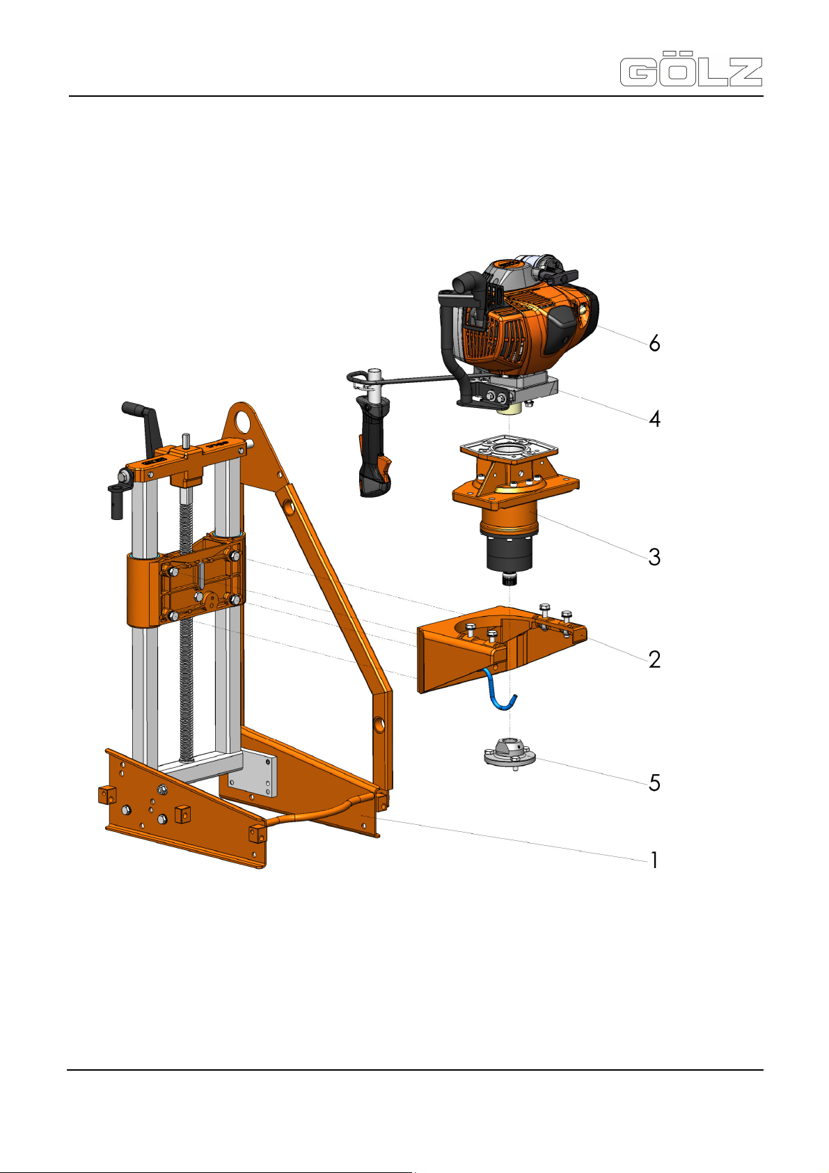
KB300 / KB350 with FS560
Translation of the original operating instruction and spare parts list
9. Exploded view and spare parts list
®
- 47-
5006892-01
BA-E
Page 48

KB300 / KB350 with FS560
Translation of the original operating instruction and spare parts list
Pos. Artikelnummer Menge Norm Info Bezeichnung Description Désignation
®
0295 302 2000
-
0295 352 2000
-
0295 301 0001
1
0295 352 0001
2
0295 002 0016
3
0295 003 0005
0295 003 0003
4
0295 003 0004
5
0295 003 0000
0295 003 0009
6
0295 003 0010
1
1
1
1
-
-
-
1 Getriebeträger Gear box carrier Support engrenage
1 Planetengetriebe kpl. Planetary gear complete
1
1
1
1 Flansch
1 UNC
1
1
1
KB 300
KB 350
EUROPA
USA
KANADA
EUROPA
USA
KANADA
KB 300 mit FS560 KB 300 with FS560 KB 300 avec FS560
KB 350 mit FS560 KB 350 with FS560 KB 350 avec FS560
Bohrständer kpl. Drill rig complete
Antriebsmotor kpl. Drive motor complete
Werkzeugaufnahme Tool acceptance Levé outillage
Motor Motor Moteur
Foreuse carotteuse
complète
Engrenage planétaire
complète
Moteur commande
complète
- 48-
5006892-01
BA-E
Page 49

KB300 / KB350 with FS560
Translation of the original operating instruction and spare parts list
9.1 Drill rig
9.1.1 Drill rig KB300
®
- 49-
5006892-01
BA-E
Page 50

KB300 / KB350 with FS560
Translation of the original operating instruction and spare parts list
Pos. Artikelnummer Menge Norm Info Bezeichnung Description Désignation
0295 301 0001
-
1 KB 300 Bohrständer kpl. Drill rig assy. Foreuse carotteuse compl.
®
0295 000 0071
1
0295 000 0047
2
0286 570 0047
3
0295 000 0187
4
0295 000 0410
5
0295 000 0175
6
0295 000 0745
7
0295 600 1043
8
0295 000 0742
9
0295 000 0081
10
0295 000 0293
11
0295 000 0074
12
0295 000 0076
13
0295 000 0092
14
0295 000 0411
15
0281 045 0027
16
0295 000 0069
17
1
1
DIN EN
12
ISO 7090
DIN EN
6
ISO 4017
DIN EN
2
ISO 4026
DIN EN
2
ISO 4026
2 Ø 15,1 Scheibe Washer Rondelle
DIN EN
2
ISO 7090
1 Buchse Bushing Douille
1 Spindel Spindle Arbre de transmission
DIN EN
4
ISO 4017
DIN EN
1
ISO 4017
1 Vierkantkupplung Connection tube Carré de manœuvre
1 Brücke kpl. Crankcase assy.
DIN EN
2
ISO 4014
DIN EN
2
ISO 7040
1 SW 12 Handkurbel Handle Manivelle
Rohrfuss Pipe base Embase
Rohrführung Column Guide en fer carré
B 10,5 Scheibe Washer Rondelle
M 10 x 20 Schraube Screw Vis
M 10 x 30 Gewindestift Set screw Tige filetée
M 10 Mutter Nut Écrou
B 15 Scheibe Washer Rondelle
M 10 x 35 Schraube Screw Vis
M 8 x 30 Schraube Screw Vis
Pond de commande
complète
M 6 x 60 Schraube Screw Vis
M 6 Mutter Nut Écrou
0295 899 0016
18
0295 000 0072
19
0295 300 0015
20
0295 000 0061
21
0295 000 0048
22
0295 000 0066
23
0298 100 0130
24
0295 300 0044
25
0286 570 0046
26
0282 300 0528
27
0295 003 0023
28
0295 000 0173
29
0295 899 0033
-
0295 899 0051
-
0295 000 0825
-
0295 300 0051
-
1 „KB300“ Aufkleber Label Macaron
1 17 x 12 x 25,5 Buchse Bushing Douille
1 Bodenrahmen Floor frame Châssis
DIN EN
1
ISO 4014
1 Bohrschlitten kpl. Carriage assy. Chariot complète
1 1/4" Dichtring Seal Joint
1 G 1/4" A Stecknippel Water coupler Raccord rapide
1 „Hebepunkt“ Aufkleber Label Macaron
DIN EN
1
ISO 4032
1 DIN 2093 28 x 10,2 x1 Tellerfeder Disk spring Ressort à disque
1 Halter Bediengriff Control holder Manche
DIN EN
1
ISO 4017
1 „Pikto“ Aufkleber Label Macaron
1 Typenschild Type plate Plaque d’identification
- - Pos. 16-19 Spindellager kpl. Spindle bearing assy.
1 Spanratsche Clamping ratchet Cliquet
M 10 x 50 Schraube Screw Vis
M 10 Mutter Nut Écrou
M 10 x 30 Schraube Screw Vis
Roulement de vis de
descente compl.
- 50-
5006892-01
BA-E
Page 51

KB300 / KB350 with FS560
Translation of the original operating instruction and spare parts list
®
- 51-
5006892-01
BA-E
Page 52

KB300 / KB350 with FS560
Translation of the original operating instruction and spare parts list
Pos. Artikelnummer Menge Norm Info Bezeichnung Description Désignation
0295 300 0053
-
0295 000 0190
-
0295 000 0003
-
0295 000 2038
-
1 Spannband Strap Sangle
2 Erdnagel Ground spike Piquet de sol
1 Klappsplint Linch pin Esse d’essieu
1 DIN 894 SW17 Maulschlüssel Wrench Clé
®
- 52-
5006892-01
BA-E
Page 53

KB300 / KB350 with FS560
Translation of the original operating instruction and spare parts list
9.1.2 Drill rig KB350
®
- 53-
5006892-01
BA-E
Page 54

KB300 / KB350 with FS560
Translation of the original operating instruction and spare parts list
Pos. Artikelnummer Menge Norm Info Bezeichnung Description Désignation
0295 352 0001
-
1 KB350 Bohrständer kpl. Drill rig assy. Foreuse carotteuse compl.
®
0295 000 0350
1
0295 000 0351
2
0295 350 0015
3
0295 000 0048
4
0295 000 0230
5
0295 351 0025
6
0295 000 0206
7
0286 570 0047
8
0295 000 0092
9
0295 000 0036
10
0281 045 0027
11
0295 000 0069
12
0295 000 0187
13
0295 000 0076
14
0295 000 0081
15
0295 600 1043
16
0295 000 0745
17
1
1
1 Bodenrahmen Floor frame Châssis
1 Bohrschlitten kpl. Carriage assy. Chariot complète
1 DIN 3771 27 x 2,5 O-Ring O-ring Joint
1 Zwischenplatte Inner plate Platine intermédiaire
1 DIN 6885 10 x 8 x 56 Paßfeder Key Clavette
DIN EN
11
ISO 7090
1 Brücke kpl. Crankcase assy.
4 DIN 7349
DIN EN
2
ISO 7040
1 SW 12 Handkurbel Handle Manivelle
DIN EN
4
ISO 4017
1 Vierkantkupplung Connection tube Carré de manœuvre
1 Spindel Spindle Arbre de transmission
DIN EN
2
ISO 7090
2 Ø 15,1 Scheibe Washer Rondelle
Rohrfuss Pipe base Embase
Rohrführung Column Guide en fer carré
B 10,5 Scheibe Washer Rondelle
Pond de commande
complète
6,4 Scheibe Washer Rondelle
M 6 Mutter Nut Écrou
M 10 x 20 Schraube Screw Vis
B 15 Scheibe Washer Rondelle
0295 000 0742
18
0295 000 0074
19
0295 000 0410
20
0295 000 0175
21
0295 000 0360
22
0286 570 0044
23
0282 250 0744
24
0295 350 0024
25
0295 000 0216
26
0295 000 0179
27
0282 250 0128
28
0295 000 0066
29
0298 100 0130
30
0295 899 0017
31
0295 000 0293
32
0282 300 0528
33
1 Buchse Bushing Douille
DIN EN
1
ISO 4017
DIN EN
2
ISO 4026
DIN EN
2
ISO 4026
1 17 x 12 x 60 Buchse Bushing Douille
DIN EN
1
ISO 4014
DIN EN
2
ISO 4017
1 Brückenverstärkung Reinforcement Garniture
3 DIN 7349 A 10,5 Scheibe Washer Rondelle
DIN EN
2
ISO 4017
DIN EN
4
ISO 4014
1 1/4" Dichtring Seal Joint
1 G 1/4" A Stecknippel Water coupler Raccord rapide
1 „KB350“ Aufkleber Label Macaron
DIN EN
1
ISO 4017
1 DIN 2093 28 x 10,2 x 1 Tellerfeder Disk spring Ressort à disque
M 8 x 30 Schraube Screw Vis
M 10 x 30 Gewindestift Set screw Tige filetée
M 10 Mutter Nut Écrou
M 10 x 90 Schraube Screw Vis
M 6 x 70 Schraube Screw Vis
M 10 x 25 Schraube Screw Vis
M 10 x 75 Schraube Screw Vis
M 10 x 35 Schraube Screw Vis
- 54-
5006892-01
BA-E
Page 55

KB300 / KB350 with FS560
Translation of the original operating instruction and spare parts list
®
- 55-
5006892-01
BA-E
Page 56

KB300 / KB350 with FS560
Translation of the original operating instruction and spare parts list
Pos. Artikelnummer Menge Norm Info Bezeichnung Description Désignation
0295 003 0023
34
0286 570 0046
35
0295 300 0044
36
0295 899 0033
-
0295 899 0051
-
0295 000 0825
-
0295 300 0051
-
0295 300 0053
-
0295 000 0190
-
0295 000 0003
-
0295 000 2038
-
1 Halter Bediengriff Control holder Manche
DIN EN
1
ISO 4032
1 „Hebepunkt“ Aufkleber Label Macaron
1 „Pikto“ Aufkleber Label Macaron
1 Typenschild Type plate Plaque d’identification
- - Pos. 16-19 Spindellager kpl. Spindle bearing assy.
1 Spanratsche Clamping ratchet Cliquet
1 Spannband Strap Sangle
2 Erdnagel Ground spike Piquet de sol
1 Klappsplint Linch pin Esse d’essieu
1 DIN 894 SW17 Maulschlüssel Wrench Clé
M 10 Mutter Nut Écrou
Roulement de vis de
descente compl.
®
- 56-
5006892-01
BA-E
Page 57

KB300 / KB350 with FS560
Translation of the original operating instruction and spare parts list
9.1.3 Carriage
Pos. Artikelnummer Menge Norm Info Bezeichnung Description Désignation
®
0295 000 0048
-
0295 000 0093
1
02950000231
2
0295 000 0206
3
0295 000 0077
4
0295 000 0037
5
0295 000 0066
6
0295 000 0063
7
1 Pos. 1-7 Bohrschlitten kpl. Carriage assy. Chariot compl.
1
4 Kunststoffbuchse Bushing Douille
DIN EN
1
ISO 6885
1 Spindelmutter Spindle nut Entretoise
DIN EN
2
ISO 4017
1 Dichtring Seal Joint
1 1/4" Ventiloberteil Water tap Robinet
Bohrschlitten Carriage Chariot
10 x 8 x 56 Passfeder Key Clavette
M 10 x 16 Schraube Screw Vis
- 57-
5006892-01
BA-E
Page 58
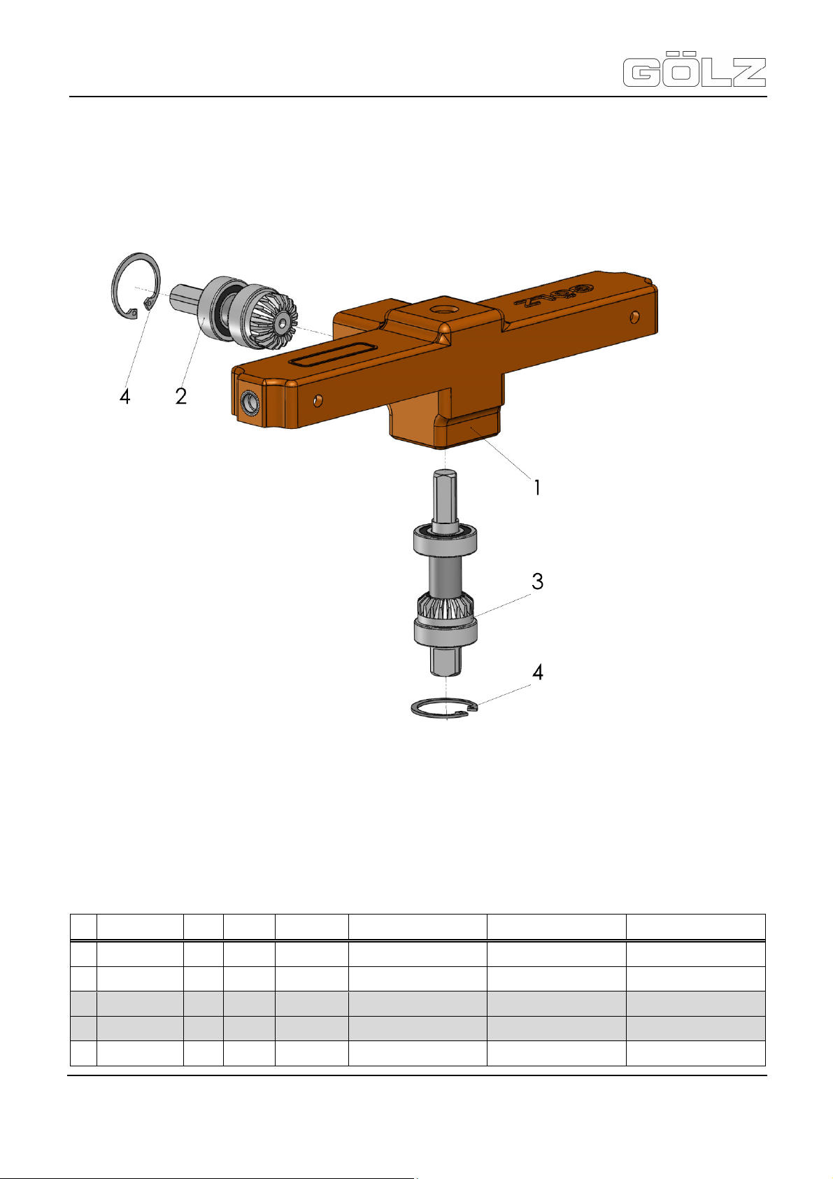
KB300 / KB350 with FS560
Translation of the original operating instruction and spare parts list
9.1.4 Crankcase
Pos. Artikelnummer Menge Norm Info Bezeichnung Description Désignation
®
0295 000 0092
-
0295 000 0046
1
0295 300 0017
2
0295 300 0018
3
0295 000 0462
4
1 Pos. 1-4 Brücke kpl. Crankcase assy. Pond de commande compl.
1
1
1 Ritzelwelle Feed shaft and bearing Pignon et roulement
2 DIN 472 35 x 1,5 Sicherungsring Circlip Circlip
Brückengehäuse Crankcase Pont de commande
Ritzelwelle Feed shaft and bearing Pignon et roulement
- 58-
5006892-01
BA-E
Page 59

KB300 / KB350 with FS560
Translation of the original operating instruction and spare parts list
9.2 Gear box carrier
Pos. Artikelnummer Menge Norm Info Bezeichnung Description Désignation
0295 300 0049
1
0286 570 0047
2
0295 000 0101
3
0286 570 0052
4
0284 000 0469
5
1 Getriebeträger Gear box carrier Support engrenage
DIN EN
4
ISO 7090
DIN EN
4
ISO 4014
DIN EN
4
ISO 7040
1 1/4", Ø 8 Einschraubsteckverbinder Connector Connecteur
B 10,5 Scheibe Washer Rondelle
M 10 x 45 Schraube Screw Vis
M 10 Mutter Nut Écrou
®
0284 000 0476
6
0295 000 0176
7
1 Ø 8 x 100 Schlauch Hose Tuyau
1 14 x 2,5 O-Ring O-ring Joint
- 59-
5006892-01
BA-E
Page 60
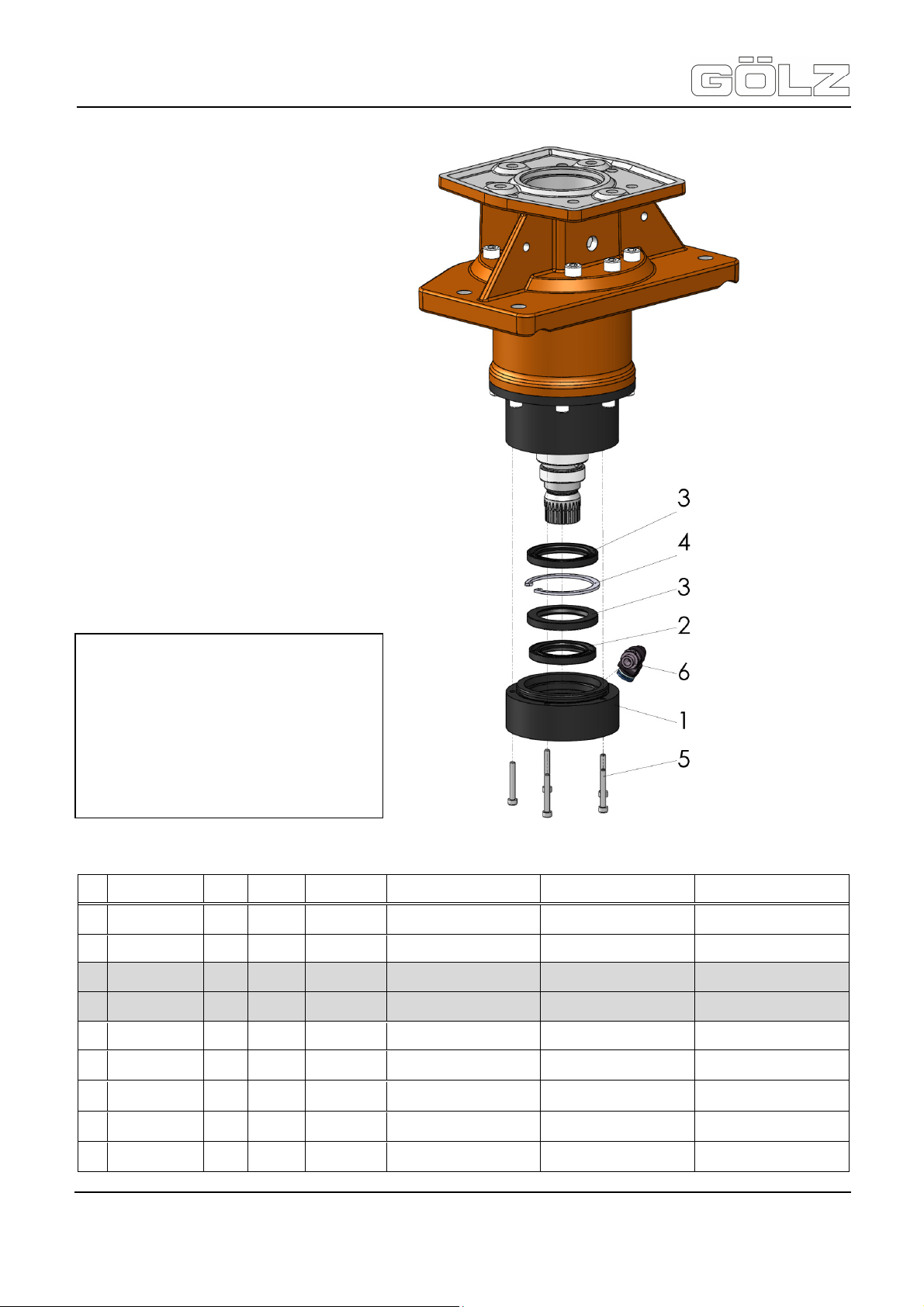
KB300 / KB350 with FS560
Translation of the original operating instruction and spare parts list
9.3 Planetary gear
Interstices of Pos. 2 and Pos. 3 fill with
waterproof fat.
Install Pos. 4 so that the hole of the
flushing drill in the groove from Pos. 1
remains free
Use Pos. 5 with Loctite 243 and tighten
to 3 Nm.
Pos. Artikelnummer Menge Norm Info Bezeichnung Description Désignation
0295 002 0016
-
0295 002 0069
1
0295 002 0068
2
0295 002 0066
3
0295 002 0067
4
0295 002 0070
5
0295 002 0065
6
0295 002 0073
-
-
1
1 Deckel Cover Couverture
1 DIN3760 35 x 525 x 6 Radialwellendichtring Radial rotary shaft seal
2 DIN 3760 40 x 55 x 6 Radialwellendichtring Radial rotary shaft seal
1 DIN 472 J 55 x 2 Sicherungsring Snap ring Circlip
DIN EN
4
ISO 4762
1 G1/8“A - Ø8
Wasserfestes Fett Water resistant fat
KB 150-350
M 4 x 30 Schraube Screw Vis
z.B. Loctite
243
Planetengetriebe kpl. Planetary gear assy.
Winkeleinschraubverschraubung drehbar
Kleber Adhesive Adhésif
Angle screwing in screw
connection swivelling
Engrenage planétaire
compl.
Bague - jointe de vague
radiale
Bague - jointe de vague
radiale
Angle vissant dans pivoter
de raccordement de vis
Graisse résistante de
l´eau
®
- 60-
5006892-01
BA-E
Page 61
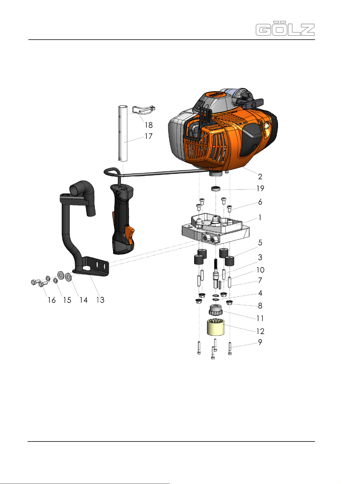
KB300 / KB350 with FS560
Translation of the original operating instruction and spare parts list
9.4 Drive motor
®
- 61-
5006892-01
BA-E
Page 62

KB300 / KB350 with FS560
Translation of the original operating instruction and spare parts list
Pos. Artikelnummer Menge Norm Info Bezeichnung Description Désignation
®
0295 003 0005
-
0295 003 0003
-
0295 003 0004
-
0295 002 0087
1
0295 000 0025
1.1
0295 000 0462
1.2
0295 003 0000
2
0295 003 0009
0295 003 0010
0295 002 0086
3
0267 118 0104
4
0295 002 0022
5
0295 000 0352
6
0282 250 0606
7
0298 000 0962
8
0295 000 0059
9
0295 002 0030
10
-
-
-
1 +Pos. 1.1-1.2 Flanschplatte kpl. Flange plate assy. Plaque de bride compl.
1 DIN 625 6202.2RS Lager Ball bearing Roulement à billes
1 DIN 472 35 x 1,5 Sicherungsring Circlip Circlip
1
1
1
1 Antriebswelle Shaft Arbre
2 DIN 471 15 x 1 Sicherungsring Circlip Circlip
4 25,5 x 22 Maschinenfuss Machine foot Pied de machine
4 DIN 7984 M 8 x 12 Schraube Screw Vis
DIN EN
4
ISO 4026
4 M 8 Mutter Nut Écrou
DIN EN
4
ISO 4762
1 DIN 6885 A 4 x 4 x 25 Paßfeder Key Clavette
Pos.1-26
EUROPA
Pos.1-26
USA
Pos.1-26
KANADA
EUROPA
USA
KANADA
M 8 x 30 Gewindestift Grub screw Goupille de fil
M 5 x 30 Schraube Screw Vis
Antriebsmotor kpl. Drive motor assy. Moteur commande compl.
Antriebsmotor kpl. Drive motor assy. Moteur commande compl.
Antriebsmotor kpl. Drive motor assy. Moteur commande compl.
Motor für KB Motor for KB Moteur de KB
Motor für KB Motor for KB Moteur de KB
Motor für KB Motor for KB Moteur de KB
11
11.1
12
13
14
15
16
17
18
19
-
-
-
-
-
-
0295 002 0014
0282 450 0119
0295 002 0013
0295 003 0028
0298 900 0008
0282 150 0036
0282 150 0035
0295 003 0022
0266 420 3024
0295 002 0103
0295 003 0024
0295 002 0077
0295 002 0078
0295 899 0345
0000 891 0801
4128 890 3400
1 +Pos. 11.1 Kupplungsnabe Clutch hub Moyeu d’embrayage
DIN EN
1
ISO 4029
1 Kupplungshülse Clutch case Cas d’embrayage
1 Abstützung Auspuff Support exhaust Soutien échappement
DIN EN
2
ISO 7093
2 DIN 127 A 8 Federring Spring washer Rondelle-ressort
DIN EN
2
ISO 4017
1 Griffaufnahme Handle Poignée
1 4,5 x 32 Rohrklappenstecker Linch pin Esse d’essieu
1 DIN 625 628.2RS Lager Ball bearing Roulement à billes
1 „Lwa“ Aufkleber Label Macaron
1 „Handschutz“ Aufkleber Label Macaron
1 „Warnung“ Aufkleber Label Macaron
1 „Verbot“ Aufkleber Label Macaron
1 Werkzeugtasche Tool kit Trousse à outils
1 Kombischlüssel Universal wrench Clés universelle
M 5 x 8 Gewindestift Grub screw Goupille de fil
A 8,4 Scheibe Washer Rondelle
M 8 x 20 Schraube Screw Vis
- 62-
5006892-01
BA-E
Page 63
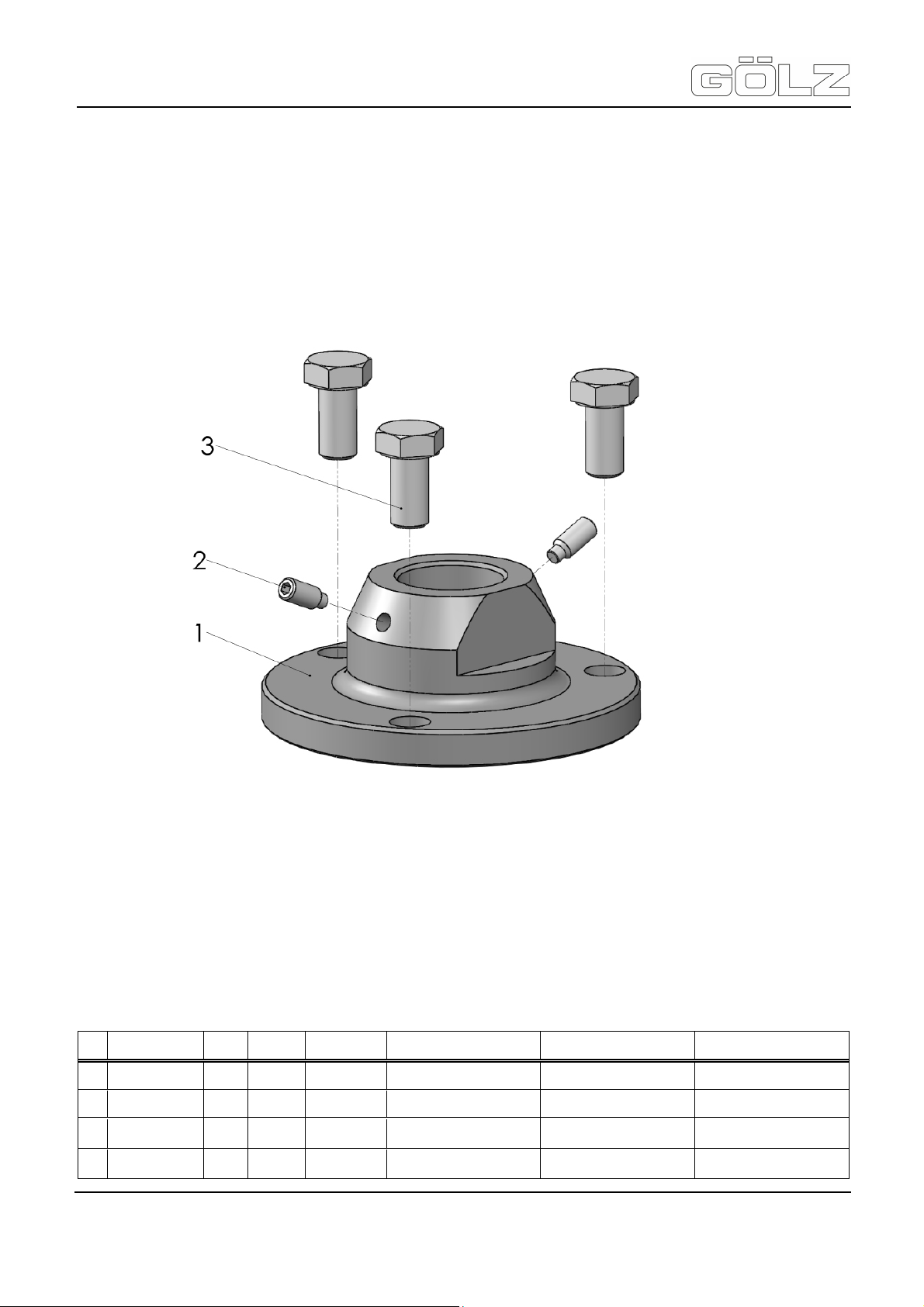
KB300 / KB350 with FS560
Translation of the original operating instruction and spare parts list
9.5 Tool acceptance
Artikelnummer Menge Norm Info Bezeichnung Description Désignation
Pos
®
-
1
2
3
-
0295 002 0000
0285 300 0026
0295 000 0187
1 Werkzeugaufnahme Tool acceptance Levé outillage
1 3-Loch-Flansch Flange Bride
DIN EN
2
3
ISO 4028
DIN EN
ISO 4017
M 6 x 14 Gewindestift Grub screw Goupille de fil
M 10 x 20 Schraube Screw Vis
- 63-
5006892-01
BA-E
Page 64

KB300 / KB350 with FS560
Translation of the original operating instruction and spare parts list
Artikelnummer Menge Norm Info Bezeichnung Description Désignation
Pos
®
-
1
2
3
4
-
0295 002 0001
0285 300 0026
0295 000 0277
0295 000 0278
1 Werkzeugaufnahme Tool acceptance Levé outillage
1 5/4“ UNC Adapter Adapter Adapter
DIN EN
2
ISO 4028
1 Zwischenscheibe Washer Rondelle
1 DIN 3771 26 x 1,9 O-Ring O-ring Joint
M 6 x 14 Gewindestift Grub screw Goupille de fil
- 64-
5006892-01
BA-E
Page 65

KB300 / KB350 with FS560
Translation of the original operating instruction and spare parts list
9.6 Motor
9.6.1 Motor - Crankcase, Cylinder
®
- 65-
5006892-01
BA-E
Page 66

KB300 / KB350 with FS560
Translation of the original operating instruction and spare parts list
Pos. Artikelnummer Menge Norm Info Benennung Description Désignation
-
1
2
3
4
5
6
7
8
12
13
14
15
16
17
18
-
4148 020 2602
9503 003 0340
0000 988 8600
9639 003 1585
4148 020 2902
9640 003 1195
9075 478 4159
4148 030 0400
9463 650 1100
4148 034 1500
4148 020 1201
4148 030 2003
1140 034 3000
9512 003 2347
4148 029 2300
1 Kurbelgehäuse, Zylinder Crankcase, Cylinder Carter, Cylindre
1 Pos. 2-4 Kurbelgehäusehälfte Crankcase Demi-carter de vilebrequin
1 DIN 625 6202 Kugellager Grooved ball bearing Roulement rainuré à billes
4 Hülse Sleeve Douille
1 DIN 3760
1 Pos. 2, 6 Kurbelgehäusehälfte Crankcase Demi-carter de vilebrequin
1 DIN 3760
4 M 5 x 24 Schraube Screw Vis
1 Kurbelwelle Crankshaft Vilebrequin
2 DIN 73130 C11 Sprengring Snap ring Jonc d’arrêt
1 11 x 7 x 32 Kolbenbolzen Piston pin Axe de piston
1 Pos. 12-16 Zylinder mit Kolben Cylinder with piston Cylindre avec piston
1
2 Ø 47 x 1,2 Verdichtungsring Piston ring Segment de piston
1
1 Zylinderdichtung Cylinder gasket Joint de cylindre
AS
15 x 25 x 5
BS
12 x 22 x 5
Pos. 12,
13, 16
11 x 14 x
15
Wellendichtring Oil seal Bague d’étanchéité
Wellendichtring Oil seal Bague d’étanchéité
Kolben Piston Piston
Nadelkranz Needle vage Cage à aiguilles
®
19
-
-
9022 341 0900
4148 007 1600
0295 000 0017
4 M5 x 28 Schraube Screw Vis
1
1 SW 17 Maulschlüssel Socket wrench Clé
Pos. 4, 6,
18
Dichtungssatz Set of gaskets Jeu de joints
- 66-
5006892-01
BA-E
Page 67

KB300 / KB350 with FS560
Translation of the original operating instruction and spare parts list
9.6.2 Motor - Rewind starter
®
- 67-
5006892-01
BA-E
Page 68

KB300 / KB350 with FS560
Translation of the original operating instruction and spare parts list
Pos. Artikelnummer Menge Norm Info Benennung Description Désignation
4148 190 4000
-
4148 190 0400
1
1110 084 9102
2
0000 190 3501
3
4147 195 8200
4
0000 195 7003
5
4147 190 0600
6
9104 003 0410
7
4147 190 1011
8
4147 195 2000
9
0000 195 7200
10
0000 958 0806
11
9460 624 0600
12
1 Pos. 1-13 Anwerfvorrichtung Rewind starter Dispositif de lancement
1 + Pos. 2 Starterdeckel Starter cover Couvercle de laceur
1 Buchse Bushing Douille
1 + Pos. 4, 5 Griff mit Anwerfseil Grip with starter rope
1 Ø 3 x 10¹⁰ Anwerfseil Starter rope Câble de lancement
1 Kappe Cap Capuchon
1 Rückholfeder Rewind spring Ressort de rappel
2 M 3 x 6 Schraube Screw Vis
1 Seilrolle Rope rotor Poulie à câble
1 Mitnehmer Carrier Entraîneur
2 Klinke Pawl Cliquet
1 Scheibe Washer Rondelle
1 DIN 6799
6 Sicherungsscheibe E-clip Anneau d’arrêt
Poignée avec câble de
lancement
®
13
16
17
18
20
21
22
23
24
-
1128 195 3500
4148 967 1505
9075 478 4159
4147 195 0600
0000 955 0802
0000 967 4054
4147 195 5400
9074 478 3005
4148 140 4400
4148 007 1000
1 Feder Spring Ressort
1 Typenschild Model plate Plaque matricule
4 5 x 24 Schraube Screw Vis
1 Starterrad Starter cup Roue de lanceur
1 M 8 x 1 Mutter Nut Écrou
1
1 Abdeckung Cover Recouvrement
2 M 4 x 14 Schraube Screw Vis
1 Luftfilter Air filter Filtre à air
1 Pos. 22-24 Satz Abdeckplatte Cover plate kit
USA
Warnhinweis Warning sign Avertissement
Jeu de pièces de plaque
de recouvrement
- 68-
5006892-01
BA-E
Page 69

KB300 / KB350 with FS560
Translation of the original operating instruction and spare parts list
9.6.3 Motor - Muffler, Shroud
®
- 69-
5006892-01
BA-E
Page 70

KB300 / KB350 with FS560
Translation of the original operating instruction and spare parts list
Pos. Artikelnummer Menge Norm Info Benennung Description Désignation
-
2
3
4
5
6
7
8
9
10
11
12
-
-
4148 140 0601
4148 140 6900
4148 084 6800
9022 341 0983
4148 149 0600
4148 141 3200
4148 080 1601
9075 478 4159
4147 084 4102
9075 478 3015
4148 080 0400
4148 007 1600
1 - Schalldämpfer, Haube Muffler, Shroud Silencieux, Capot
1 Schalldämpfer Muffler Silencieux
1 Stutzen mit Gitter Stub with screen Embout avec grille
1 Distanzstück Spacer Pièce d’écartement
3 M 5 x 16 Schraube Screw Vis
1 Schalldämpferdichtung Muffler gasket Joint de silencieux
1 Kühlblech Cooling plate Tôle de refroidissement
1 Haube Shroud Capot
2 M 5 x 24 Schraube Screw Vis
1 Schieber Shutter Tiroir
2 M 4 x 15 Schraube Screw Vis
1 Abdeckung Cover Recouvrement
1 Pos. 6 Dichtungssatz Set of gaskets Jeu de joints
®
- 70-
5006892-01
BA-E
Page 71

KB300 / KB350 with FS560
Translation of the original operating instruction and spare parts list
9.6.4 Motor - Fuel tank
®
- 71-
5006892-01
BA-E
Page 72

KB300 / KB350 with FS560
Translation of the original operating instruction and spare parts list
Pos. Artikelnummer Menge Norm Info Benennung Description Désignation
4148 350 0401
1
4147 350 5802
2
4223 353 9201
3
4148 358 7700
4
4224 122 3900
5
6
0000 937 5004
0000 937 4080
7
4148 358 0800
8
0000 350 3502
9
4148 353 2700
10
1141 989 0600
11
0000 350 0517
12
9645 951 3890
13
1 Pos. 2-15 Kraftstofftank Fuel tank Réservoir d’essence
1 Tankfüllung Tank vent Aération de réservoir
1 Tülle Grommet Douille
1 Schlauch Hose Tuyau
1 Winkelstutzen Elbow connector Raccord en équerre
1
1
1 Schlauch Hose Tuyau
1 Schlauch Hose Tuyau
1 Saugkopf Pickup body Crépine d’aspiration
1 Verbindungsstück Connector Pièce de raccordement
1 Tülle Grommet Douille
1
1 A 35 x 3 O-Ring O-Ring Joint
3,1 x 2,7
x 137
3,1 x 5,7
x 1, R5
+ Pos. 13,
14
Schlauch Hose Tuyau
Schlauch Hose Tuyau
Tankverschluss Filler cap Bouchon de réservoir
®
14
15
16
17
18
19
20
0000 350 0900
0000 937 5004
4148 350 6200
4148 350 6600
9075 478 4167
0000 967 3693
1 Seil Rope Corde
1
1
1
1
1 Schutzplatte Guard plate Plaque de protection
4 M 5 x 32 Schraube Screw Vis
1
3,1 x 5,7
x 108
3,1 x 5,7
x 155
3,1 x 5,7
x 1m, R5
+ Pos. 15,
16
USA
Schlauch Hose Tuyau
Schlauch Hose Tuyau
Schlauch Hose Tuyau
Kraftstoffpumpe Fuel pump Pompe à carburant
Warnhinweis Warning sign Pictogramme
- 72-
5006892-01
BA-E
Page 73

KB300 / KB350 with FS560
Translation of the original operating instruction and spare parts list
9.6.5 Motor - Spacer flange, Air filter, Filter housing
®
- 73-
5006892-01
BA-E
Page 74

KB300 / KB350 with FS560
Bride intermédiaire, Filtre à
Jeu de pièces de leviers de
Translation of the original operating instruction and spare parts list
Pos. Artikelnummer Menge Norm Info Benennung Description Désignation
-
4148 120 2300
1
4148 182 9600
2
9022 341 1045
3
4148 129 0900
4
4148 182 2800
5
9460 624 0400
6
4148 182 1500
7
4148 129 0901
8
4148 120 0601
9
4148 120 9500
10
4148 140 2800
11
4134 123 7500
12
-
1
1 Zwischenflansch Spacer flange Bride intermédiaire
1 Masseblech Ground plate
4 M 5 x 24 Schraube Screw Vis
1 Dichtung Gasket Joint
1 Hebel Lever Levier
1 DIN 6799
1 Gasgestänge Throttle rod Tringlerie des gaz
2 Dichtung Gasket Joint
1 HDA-302A Vergaser Carburettor Carburateur
1 Satz Vergaserhebel Set of carburettor levers
1 + Pos. 12 Filtergehäuse Filter housing Boîtier de filtre
1 Tülle Grommet Douille
Zwischenflansch, Luftfilter,
Filtergehäuse
4 Sicherungsscheibe E-clip Anneau d’arrêt
Spacer flange, Air filter,
Filter housing
air, Boiter de filtre
Plaquette de mise à la
masse
carburateur
®
13
14
15
16
17
18
19
20
21
22
4148 352 8200
9074 478 3005
4148 350 6200
0000 937 5004
9216 261 0700
4148 141 0300
4148 140 1000
4148 141 9800
9075 478 3015
4148 007 1600
1 Halter Clamp Crampon
2 M 4 x 14 Schraube Screw Vis
1
1
1
1
2 EN 1664 M 5 Mutter Nut Écrou
1 Luftfilter Air filter Filtre à air
1 Filterdeckel Filter cover Couvercle de filtre
1 Tülle Grommet Douille
2 M 4 x 15 Schraube Screw Vis
1 + Pos. 4, 8 Dichtungssatz Set of gaskets Jeu de joints
+ Pos. 16,
17
3,1 x 5,7
x 108
3,1 x 5,7
x 155
3,1 x 5,7
x 1m, R5
Kraftstoffpumpe Fuel pump Pompe à carburant
Schlauch Hose Tuyau
Schlauch Hose Tuyau
Schlauch Hose Tuyau
- 74-
5006892-01
BA-E
Page 75

KB300 / KB350 with FS560
Translation of the original operating instruction and spare parts list
9.6.6 Motor - Carburetor
®
- 75-
5006892-01
BA-E
Page 76

KB300 / KB350 with FS560
Jeu de pièces de leviers de
Translation of the original operating instruction and spare parts list
Pos. Artikelnummer Menge Norm Info Benennung Description Désignation
4148 120 0601
-
4116 121 5100
1
4116 122 3002
2
4116 121 5000
3
1113 121 9200
4
1114 122 7400
5
4148 129 0903
6
4148 121 4700
7
4148 120 3200
8
1121 122 7101
9
1114 121 7800
10
4116 11 4800
11
4203 129 0902
12
1 Pos. 1-17 Vergaser HDA-302A Carburetor HDA-302A Carburateur HDA-302A
1 Einlassnadel Inlet needle Pointeau d’admission
1 Feder Spring Ressort
1 Einlassregelhebel Inlet control lever
1 Achse Spindle Axe
1 Schraube Screw Vis
1 Dichtung Gasket Joint
1 Regelmembrane Metering diaphragm Membrane de réglage
1 Regeldeckel Metering cover
4 Schraube Screw Vis
1 Sieb Strainer Tamis
1 Pumpenmembrane Pump diaphragm Membrane de pompe
1 Dichtung Gasket Joint
Levier de réglage
d’admission
Couvercle d’éléments de
régulation
®
4148 125 0200
13
4148 122 7100
14
4148 121 3500
15
1121 122 7102
16
4148 120 9500
17
4148 007 1700 1
-
1 Pumpendeckel Pump cover Couvercle de pompe
1 Schraube Screw Vis
1 Drosselhebel Throttle lever Levier de papillon
1 Schraube Screw Vis
1 Satz Vergaserhebel Set of carburettor levers
1
Pos. 6, 7,
11, 12
Satz Vergaserteile Set of carburettor parts
carburateur
Jeu de pièces de carbura-
teur
- 76-
5006892-01
BA-E
Page 77
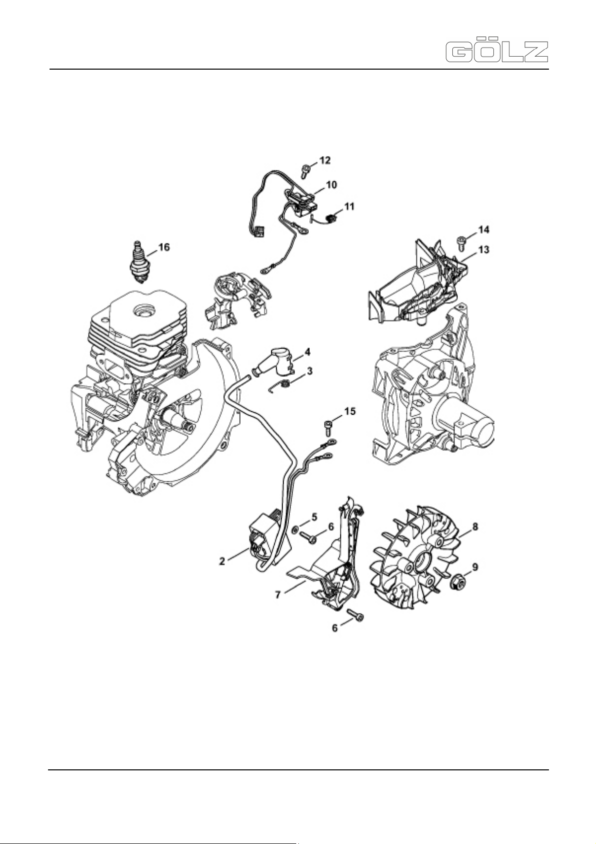
KB300 / KB350 with FS560
Translation of the original operating instruction and spare parts list
9.6.7 Motor - Ignition system
®
- 77-
5006892-01
BA-E
Page 78

KB300 / KB350 with FS560
Translation of the original operating instruction and spare parts list
Pos. Artikelnummer Menge Norm Info Benennung Description Désignation
-
2
3
4
5
6
7
8
9
10
11
12
13
-
4148 400 4710
0000 998 0604
1128 405 1000
9291 021 0100
9075 478 3018
4148 352 3000
4148 400 1200
0000 955 0802
4148 430 1000
0000 430 4801
9074 478 3005
4148 448 1201
1 Zündanlage Ignition system Dispositif d’allumage
1 + Pos. 3, 4 Steuergerät Control unit Appareil de commande
1 Schenkelfeder Torsion spring Ressort coudé
1 Zündleitungsstecker Spark plug boot
DIN EN
2
ISO 7089
4 M 4 x 18 Schraube Screw Vis
1 Abdeckung Cover Recouvrement
1 Schwungrad Flywheel Rotor
1 M 8 x 1 Mutter Nut Écrou
1 Schaltgerät Trigger unit Appareil de distribution
1 Stopfen Plug Bouchon
2 M 4 x 14 Schraube Screw Vis
1 Kabelhalter Lead retainer Attache de câble
A 4,3 Scheibe Washer Rondelle
Contact de câble
d’allumage
®
14
15
16
9075 478 4115
9074 478 3005
0000 400 7000
2 M 5 x 16 Schraube Screw Vis
2 M 4 x 14 Schraube Screw Vis
1
NGK
BPMR7A
Zündkerze Spark plug Bougie
- 78-
5006892-01
BA-E
Page 79
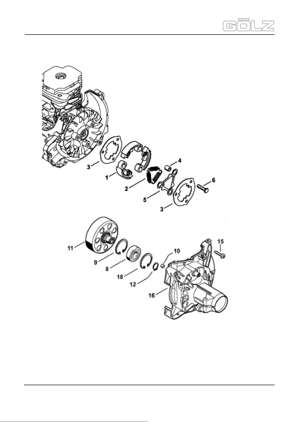
KB300 / KB350 with FS560
Translation of the original operating instruction and spare parts list
9.6.8 Motor - Clutch, Clutch housing
®
- 79-
5006892-01
BA-E
Page 80

KB300 / KB350 with FS560
Translation of the original operating instruction and spare parts list
Pos. Artikelnummer Menge Norm Info Benennung Description Désignation
-
4148 160 2000
-
-
1
1 Pos. 1-5 Kupplung Clutch Embrayage
Kupplung,
Kupplungsgehäuse
Clutch, clutch housing
Embrayage, Carter
d’accouplement
®
1
2
3
4
5
6
8
9
10
11
12
15
16
18
0000 997 5904
0000 961 0800
0000 951 0600
9503 003 7450
9456 621 3860
0000 988 8600
4148 160 2901
9455 621 1520
9075 478 4159
4148 160 0604
9456 621 3860
3 Fliehgewicht Clutch shoe Masselotte
3 Zugfeder Tension spring Ressort de tension
2 Abdeckscheibe Cover washer Rondelle de recouvrement
3 Ring Ring Anneau
1 Federscheibe Spring washer Rondelle-ressort
3 M 6 Schraube Screw Vis
1 DIN 625 6202-2RS Lager Grooved ball bearing Roulement rainuré à billes
1 DIN 472 35 x 1,5 Sicherungsring Circlip Circlip
2 Hülse Sleeve Douille
1 Kupplungstrommel Clutch drum Cloche d’embrayage
1 DIN 471 15 x 1 Sicherungsring Circlip Circlip
4 M 5 x 24 Schraube Screw Vis
1 Pos. 8-10 Kupplungsgehäuse Clutch housing Carter d’accouplement
1 DIN 472 35 x 1,5 Sicherungsring Circlip Circlip
- 80-
5006892-01
BA-E
Page 81

KB300 / KB350 with FS560
Translation of the original operating instruction and spare parts list
9.6.9 Motor - Handlebar
®
- 81-
5006892-01
BA-E
Page 82

KB300 / KB350 with FS560
Translation of the original operating instruction and spare parts list
Pos. Artikelnummer Menge Norm Info Benennung Description Désignation
4148 790 1303
-
7
8
9
10
11
12
13
14
15
16
17
18
19
20
23
4148 790 0301
4147 442 1600
4147 182 2801
4147 182 4502
9371 470 2683
4144 180 1501
0000 953 0808
4144 182 2801
4144 182 4500
4144 182 0800
4128 182 4501
9074 478 3025
9022 341 1220
9214 320 0700
4148 180 1100
1 Pos. 7-20 Bedienungsgriff Handlebar Poignée tubulaire
1 Handgriff Handle Poignée
1 Kontaktfeder Contact spring Ressort de connexion
1 Hebel Lever Levier
1 Schenkelfeder Torsion spring Ressort coudé
1 DIN 7 5 m6 x 28 Stift Pin Goupille
1 + Pos. 13 Gashebel Throttle trigger Manette des gaz
1 Stiftschraube Stud Goujon fileté
1 Hebel Lever Levier
1 Schenkelfeder Torsion spring Ressort coudé
1 Sperrhebel Lockout lever Levier d’arrêt
1 Schenkelfeder Torsion spring Ressort coudé
3 M 4 x 16 Schraube Screw Vis
1
1 DIN 980 M 5 Mutter Nut Écrou
1 Gaszug Throttle cable
M 5 x 48
x 22
Schraube Screw Vis
Câble de commande des
gaz
®
- 82-
5006892-01
BA-E
 Loading...