

Page 1
KB 125
Bedienungsanleitung / Operating instructions / Mode d’emploi
- 1-
02951250999
5004593-02
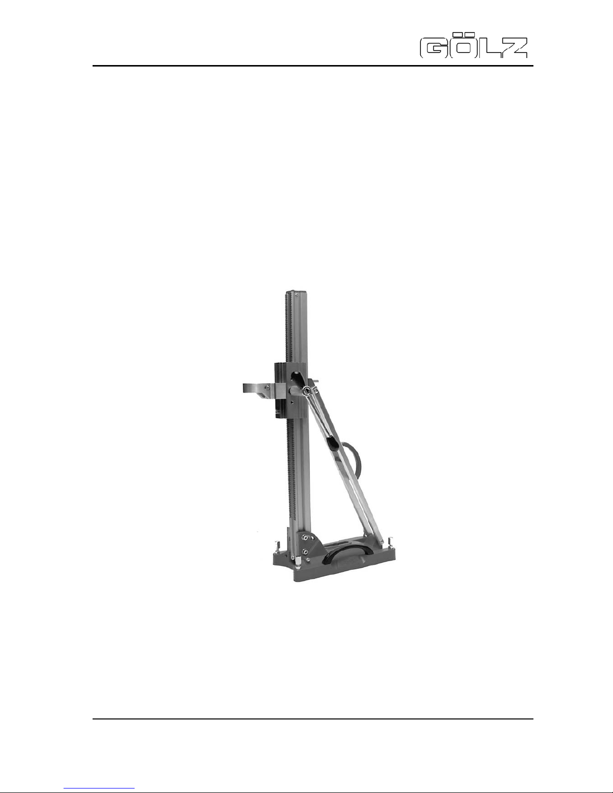
Bohrständer
Drill Rig
Foreuse carotteuse
KB 125
Art.-Nr. der Bedienungsanleitung 02951250999
ZN der Bedienungsanleitung: 5004593-02
Erstellt am : 03 / 2010
Erstellt von: Mireille Birkhahn
Datei: K:\KDV\5004xxx\5004593- Bedienungsanleitung\
5004593-02-Bedienungsanleitung-doc.doc
GÖLZ GmbH
Dommer sbach 51
53940 Hellenthal-Blum enthal
Telefon: (02482) 120
Telefax: (02482) 12135
Page 2

KB 125
Bedienungsanleitung / Operating instructions / Mode d’emploi
- 2-
02951250999
5004593-02
EG-KONFORMITÄTSERKLÄRUNG
EC-DECLARATION OF CONFORMITY
DECLARATION DE CONFORMITE DE LA CE
Die Fi rma
Manufacturer La Société
GÖLZ GmbH
Dommersbach 51, 53940 Hellenthal - Blumenthal
Tel.: (02482) 120 Fax: (02482) 12135
Erklärt in alleiniger Verantwortung, dass
folgendes Produkt:
KB 125
Kernbohrständer
Hereby certifies on it’s sole responsibility
that the following product:
KB 125
Drill rig
Déclare sous sa seule responsabilité que
le produit suiv ant:
KB 125
Foreuse carot t euse
Seriennummer / Serial number / Numéro de série: _______________________
Auf das sic h diese Erklärung bezieht, mit
folgenden Richtlinien bzw. Normen übereinstimmt:
Maschinenrichtlinie 2006/42/EG
Sicherheits- und Gesundheitsanforderung
EMV-Richtlinie 2004/108/EG
Elektromagnetische Verträglichkeit
Europäische Normen
EN 12348:2000
EN 13309:2000
EN 61000
Die oben genannte Firma hält Dokumentationen als Nachweis der Erfüllung
der Sicherheitsziele und die wesentlichen Schutzanforderungen zur Einsicht
bereit.
W hich is explicitly referred to by this declaration meet the following directives
and standard(s):
Directive 2006/42/EC
Safety and health requirement
Directive 2004/108/EC
Electromagne tic compatibility
European Stan dard
EN 12348:2000
EN 13309:2000
EN 61000
Documented evidence conforming with
the requirements of the Directive is kept
available for inspection at the above
Manufacturer's, address.
Qui fait l‘objet de la présente déclaration
correspond aux directives et normes
suivantes:
Directive 2006/42/CE
Prescriptions sanitaire et sécurité
Directive 2004/108/CE
Compatibilité électromagnétique
Norme européenne
EN 12348:2000
EN 13309:2000
EN 61000
Pour faire foi de la conformité et du respect des règles de sécurité, la documentation peut être consultée au siège
de la Société susmentionnée.
Blumenthal, den 29.03.2010 ...............................................
Leiter Einkauf / Chief buyer / Directuer des achats
Page 3

KB 125
Bedienungsanleitung / Operating instructions / Mode d’emploi
- 3-
02951250999
5004593-02
Inhaltsverzeichnis / Contents / Sommaire
1.0 Einführung............................................................................................................. 7
1.1 Vorwort.....................................................................................................................................7
1.2 Gültigkeit...................................................................................................................................7
1.3 Normen....................................................................................................................................7
2.0 Allgemeine Sicherheit............................................................................................ 7
2.1 Einführung................................................................................................................................7
2.2 Grundregel n..............................................................................................................................7
2.3 Persönlicher Schutz..................................................................................................................8
2.4 Maschinen................................................................................................................................8
2.5 Umgebung................................................................................................................................9
2.6 Erklärung der ver wendeten S y mbole.........................................................................................9
3.0 Beschreibung ...................................................................................................... 10
3.1 Hauptbestandtei le...................................................................................................................10
3.2 Funktion..................................................................................................................................10
3.2.1 Allgem ein.................................................................................................................................... 10
3.2.2 Vorschub.................................................................................................................................... 11
3.2.3 Fußplatt e.................................................................................................................................... 11
3.2.4 Transport....................................................................................................................................11
3.2.5 Waagerecht / schräg st ellen.....................................................................................................11
3.2.6 Bohrmot or und Mot or pl atte....................................................................................................... 11
4.0 Gebrauch des Kernbohrständers......................................................................... 12
4.1 Aufstellen................................................................................................................................12
4.1.1 Fixieren.......................................................................................................................................12
4.1.2 Gerät waagerecht / schr äg stellen............................................................................................12
4.1.3 Montage von Motor und Diamantbohrkrone............................................................................ 12
5.0 Wartung und Pflege............................................................................................. 13
5.1 Präventive Wartung.................................................................................................................13
5.2 Führungsstopfen einstellen und ersetzen ................................................................................13
5.2.1 Führungsstopfen einstellen....................................................................................................... 13
5.2.2 Führungsstopfen ersetzen........................................................................................................14
5.3 Abtransport von Materialien.....................................................................................................14
6.0 Garantie............................................................................................................... 14
6.1 Zeitraum.................................................................................................................................14
6.2 Umfang...................................................................................................................................14
6.3 Bestimmungen ..................................................................................................... 14
Page 4

KB 125
Bedienungsanleitung / Operating instructions / Mode d’emploi
- 4-
02951250999
5004593-02
1.0 Introduction......................................................................................................... 15
1.1 Preface...................................................................................................................................15
1.2 Validity....................................................................................................................................15
1.3 Norms....................................................................................................................................15
2.0 General safety ..................................................................................................... 15
2.1 Introduction.............................................................................................................................15
2.2 Basic rules..............................................................................................................................15
2.3 Personal protec tion................................................................................................................. 16
2.4 Machines................................................................................................................................16
2.5 Environment............................................................................................................................16
2.6 Explanati on of t he used sym bol s.............................................................................................17
3.0 Description .......................................................................................................... 18
3.1 Principal c om ponents.............................................................................................................. 18
3.2 Function..................................................................................................................................18
3.2.1 In general ...................................................................................................................................18
3.2.2 Feed............................................................................................................................................ 19
3.2.3 Base plate .................................................................................................................................. 19
3.2.4 Transport....................................................................................................................................19
3.2.5 Position – hori z ontal / oblique................................................................................................... 19
3.2.6 Drill rig motor and motor plate.................................................................................................. 19
4.0 Usage of the core drill rig..................................................................................... 20
4.1 Setting up............................................................................................................................... 20
4.1.1 Fixing..........................................................................................................................................20
4.1.2 Positioning of the machine – horizontal / oblique....................................................................20
4.1.3 Mounting of the motor and the diamond drill bit...................................................................... 20
5.0 Main t en ance an d care.......................................................................................... 21
5.1 Preventive m aintenance.......................................................................................................... 21
5.2 Adjustment and replacement of guide plugs ............................................................................ 21
5.2.1 Adjustm ent of guide plugs.........................................................................................................21
5.2.2 Replacem ent of guide plugs..................................................................................................... 22
5.3 Removal of material................................................................................................................22
6.0 Gu arentee............................................................................................................ 22
6.1 Period.....................................................................................................................................22
6.2 Outline....................................................................................................................................22
6.3 Regulations.............................................................................................................................22
Page 5

KB 125
Bedienungsanleitung / Operating instructions / Mode d’emploi
- 5-
02951250999
5004593-02
1.0 Introduction......................................................................................................... 23
1.1 Préambule..............................................................................................................................23
1.2 Validité....................................................................................................................................23
1.3 Normes..................................................................................................................................23
2.0 Consignes de sécurité......................................................................................... 23
2.1 Introduction.............................................................................................................................23
2.2 Règles de base.......................................................................................................................23
2.3 Protecti on des personnes........................................................................................................24
2.4 Machine..................................................................................................................................24
2.5 Environnem ent........................................................................................................................24
2.6 Symboles utilisés....................................................................................................................25
3.0 Description .......................................................................................................... 26
3.1 Composants princi paux...........................................................................................................26
3.2 Fonctions................................................................................................................................26
3.2.1 Généralit és................................................................................................................................. 26
3.2.2 Avance........................................................................................................................................ 27
3.2.3 Socle ........................................................................................................................................... 27
3.2.4 Transport....................................................................................................................................27
3.2.5 Réglage inclinaison de la colonne ............................................................................................ 27
3.2.6 Monteur de carot tage et plaque de fixation monteur .............................................................. 27
4.0 Utilisation du bâti carottage................................................................................. 28
4.1 Mise en place..........................................................................................................................28
4.1.1 Fixati on....................................................................................................................................... 28
4.1.2 Réglage de l’inclinaison de la colonne.....................................................................................28
4.1.3 Montage du moteur et de la couronne diamant ......................................................................28
5.0 Entretien.............................................................................................................. 29
5.1 Entretien préventif ...................................................................................................................29
5.2 Réglage et rempl ac em ent des gui des du chariot.....................................................................29
5.2.1 Réglage des glissoirs ................................................................................................................29
5.2.2 Remplac em ent des glissoirs..................................................................................................... 30
5.3 Recyclage des mat éri aux........................................................................................................30
6.0 Garantie............................................................................................................... 30
6.1 Durée......................................................................................................................................30
6.2 Conditions...............................................................................................................................30
6.3 Consignes...............................................................................................................................30
Page 6

KB 125
Bedienungsanleitung / Operating instructions / Mode d’emploi
- 6-
02951250999
5004593-02
7.0 Verschleißteile / Wearing parts / Pièces d’usure .................................................. 31
8.0 Ersatzteilliste / Spare parts list / Liste des pièces de rechange............................ 34
Page 7

KB 125
Bedienungsanleitung / Operating instructions / Mode d’emploi
- 7-
02951250999
5004593-02
1.0 Einführung
1.1 Vorwort
Diese Betri ebsanleitung di ent dazu, Si e in die sicher e Arbeit m it dem GÖLZ Kernbohr ständer einzuweisen. Bei der Anf er ti gung di eser Betr iebsanl eit ung wurde v on der Bedi enung erf ahrener Anwender
ausgegangen. Die Betriebsanleitung um fasst die wichtigsten Informationen für das Aufstellen, Bedi enen, Abbauen und Warten der Maschine.
1.2 Gültigkeit
Diese Betriebsanl eitung dient ausschließlic h dem Einsatz des GÖLZ Kernbohrständers.
1.3 Normen
Die Betriebsanleitung ist CE - K onform.
2.0 Allgemeine Sicherheit
2.1 Einführung
Um G efahren wie Str omschlag, Feuer oder Verletzungen v orzubeugen, beachten Si e die folgenden
Sicherhei tsvorkehrungen. Lesen Sie di ese Informat ionen aufm erksam und befolgen S ie die Ratschläge.
2.2 Grundregeln
Beugen Sie einem Stromschlag vor.
Ein wassergekühlter Elektromotor mit Randerde darf nur eingesetzt werden, wenn das gesamte
System kom pl ett geerdet i st und über ei n einwandf rei f unk ti oni erendes Erdsicher ungssystem (F I B ox
oder PCRD) an das Strom netz angeschlossen wird. Der Restst r om der Erdsicherung darf 30 mA nicht
überschreiten. Testen Sie das System, bevor Sie mit der A r beit beginnen.
Ein doppel tisolierter wassergekühlter El ektromotor ohne Randerdung darf nur mit einem speziellen
CEE-Stecker 16-12h über ei nen Trenntransform ator (1:1) an das Str omnetz angeschlossen werden.
Der speziell e CEE-Stecker (geei gnet für den Ei nsatz mit FI- Box oder Trenntransform ator) darf nicht
entfernt oder durch ei nen anderen Steck er ersetzt werden. Bei Zweif el fragen Si e einen qualif izi erten
Elektrofachmann.
Wasser und Elektrizität.
Stell en S ie sic her, dass der Anschl uss des Wasserschlauches ni cht t ropf t , lec kt oder sich sogar l ösen
kann. Beim Bohren oder Sägen Überkopf soll das Kühlwasser immer beachtet werden. Bei
Überkopfbohrungen muss immer ein Wassersammelring benutzt werden. Bei Arbeiten in der Wand ist
das zu empfehlen. Führen Sie das Kühlwasser immer sicher ab, zum Beispiel mit einem
Wassersauger. Kabel, Stecker und E lektrizität dürfen nicht m it Wasser in Verbindung kom men.
Page 8

KB 125
Bedienungsanleitung / Operating instructions / Mode d’emploi
- 8-
02951250999
5004593-02
Seien Sie immer aufmerksam.
Achten Sie auf Ihre Arbeit, nutzen Sie Ihren Verstand und arbei ten Sie nur mit der Maschine wenn Sie
konzentrier t sind. Ac hten Si e darauf, dass Sie im mer in der Lage sind den Motor schnell ausschalten
zu können. Nutzen Si e keine Maschinen, bei denen der S c halter nicht ein- oder ausgeschaltet werden
kann.
2.3 Persönlicher Schutz
Tragen Sie geeignete Arbeitskleidung.
Tragen Sie kei ne weite Kleidung oder Schm uck. Diese können zwischen bewegliche T eile geraten.
Bei Arbeiten im Freien wird das Tragen von Gummihandschuhen und Schuhen mit Profilsohlen
empf ohlen. Tragen Si e bei langem Haar ein Haarnetz.
Nutzen Sie persönliche Schutzmittel
Tragen Sie ei nen Schutzhelm gegen herunt erfallende Gegenstände, Handschuhe als Schutz gegen
scharfe Tei le und eine Sicherheitsbrille als Schutz gegen Steinschlag oder Funkenf lug. Tragen Sie
eine Atemschutzmaske bei Arbeiten mit hoher Staubentwicklung. Gehörschutz wird empfohlen bei
einen Lärmpegel ab 80 dB (A), über 85 dB ( A ) ist das Tragen v on Gehörschutz Pflicht!
2.4 Maschinen
Werkzeugpflege
Halten Si e das Werkzeug schar f und sauber um besser und sicherer arbeit en zu können. Halten Sie
sich an die Wartungsvorschriften. Halten Sie die Handgriffe troc ken und frei von Öl und Fett.
Kontrollieren Sie die Maschine auf Beschädigungen
Kontrollieren Sie die einwandfreie Funktion von beweglichen Teilen, ob diese nicht klemmen,
gebrochen oder richtig montiert sind und alle anderen Vorraussetzungen für die einwandfreie
Funktion der Maschine gegeben sind. Beschädigte Teile müssen durch eine anerkannte Fachkraft
fachmännisch ersetzt oder repar iert werden.
Benutzung von Zubehör und Hilfsmittel
Nutzen Sie nur Zubehör und Hilfsmitt el, welche in der Betr iebsanleitung oder Katalog erwähnt werden.
Der Einsatz von anderem Z ubehör oder Hilfsmittel n kann zu Verletzungen führen.
Kabel/Verlängerungskabel
Nutzen Sie nur unbeschädi gte Verlängerungskabel, die für den Ei nsatz im Freien geeignet sind und
deren Querschnitt der Ader ausreichend ist. Rollen Sie eine Kabeltrommel komplett ab, um
Überhitzung vorzubeugen. T ragen Sie di e Maschine nie am Kabel und nutzen Sie das Kabel auch
nicht, um den Stecker aus der K ontaktdose zu ziehen. Schützen Si e das Kabel gegen Hitze, Öl und
scharfe Kanten.
Reparatur von Elektrogeräten
Elektrogeräte müssen den gültigen Sicherheitsbestimmungen entsprechen. Reparaturen dürfen
deshalb ausschließl ich v on anerk annten Elek trof achkräf ten durc hgeführt werden, da sonst Gefahr für
den Anwender entstehen kann.
Page 9
KB 125
Bedienungsanleitung / Operating instructions / Mode d’emploi
- 9-
02951250999
5004593-02
2.5 Umgebung
Achten Sie auf einen sauberen Arbeitsplatz
Ein unordentlicher Arbeitsplatz kann zu Unfällen führen. Lassen Sie nicht zu, dass unbefugte
Personen (Kinder) den Ar beitsplatz bet r eten oder die Geräte bedienen können. Stel len Sie sicher,
dass während Bohr- oder Sägearbeiten die ausgebohrten- oder gesägten Teile aufgefangen oder
abgestützt werden (insbesondere bei Bohr- oder Sägearbeit en in Böden oder Decken). Sic hern Sie
die Ger äte nach beenden der Arbeit für Unbefugte und bewahren Sie sie, wenn mögli ch, in einem
abgeschlossen Raum (nicht in Bereichen von Kindern) auf.
Beachten Sie die gesamte Umgebung des Arbeitsplatzes
Sorgen Sie für eine gute Beleuchtung. Achten Sie auf die Lage der Kabel, Leitungen und
Bewehrungseisen. Nutzen Sie ni e elektri sche Wer kzeuge in einem feucht en Umf eld (Regen) oder in
der Nähe von br ennbar en S toff en.
Sorgen Sie für einen sich eren Arbeitsplatz.
Befestigen Sie die Geräte und dazugehörende Werkzeuge sicher, so dass sie sich nicht lösen
können. Kontrollieren Sie, bevor die Geräte eingeschaltet werden, ob alle Schlüssel und andere
Hilf smittel entfer nt wurden. Sorgen Sie dafür , dass Blattschutze sicher m ontiert si nd und halten Sie
imm er einen sicheren Abstand zu si ch bewegenden Teilen. Vermei den Sie abnorme Körperhal tung
und sorgen Sie für ein stabiles Gl eichgewicht.
2.6 Erklärung der verwendeten Symbole
In der Betriebsanleitung werden neben dem Kapitel allgemeine Sicherheit die nachfolgenden drei
Symbol e verwendet um den A nwender zu warnen.
Missachtung dieser Warnung bedeutet Verletzungsgefahr .
Missachtung dieser Warnung kann zur Beschädigung des Gerätes führen.
Tipp: Beac htung führt zu einem ef fizi enteren Einsatz.
Page 10
KB 125
Bedienungsanleitung / Operating instructions / Mode d’emploi
- 10-
02951250999
5004593-02
3.0 Beschreibung
3.1 Hauptbestandteile
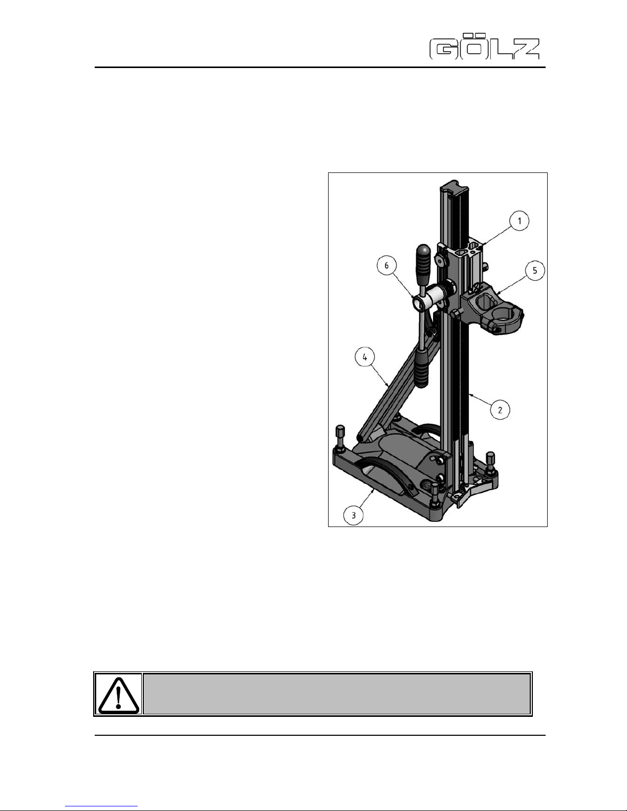
In Bild 3-1 sind die wichtigsten Hauptbestandteile angegeben. Für eine detaillierte Zeichnung der
Kernbohrständer verweisen wir auf di e E xplosionszeichnung.
Der Kernbohrständer besteht aus 6 Hauptbestandteilen:
1. Schlitten / Vorschub
2. Säule / Hol m
3. Dübelfußplatte
4. Abstützstange
5. Motorhalsaufnahme
6. Drehkreuz
3.2 Funktion
3.2.1 Allgemei n
Der verstellbare Kernbohrständer entstammt der Serie von Kernbohrständern zum Bohren mit
Diamantbohrern. Diese Bohrer sind geeignet für das Bohren in Beton, Asphalt und Gestein. Der
Bohrständer hat die F unktion, die Bohr maschine i n Positi on zu bri ngen und während des Bohrens zu
führen. Den maxim alen Durchmesser für di ese Bohrständer entnehmen Sie bitte dem technischen
Datenblatt.
Für andere als oben genannte
Anwendungen
darf der Ker nbohr ständer nicht benutzt werden !
Bild 3-1
Page 11
KB 125
Bedienungsanleitung / Operating instructions / Mode d’emploi
- 11-
02951250999
5004593-02
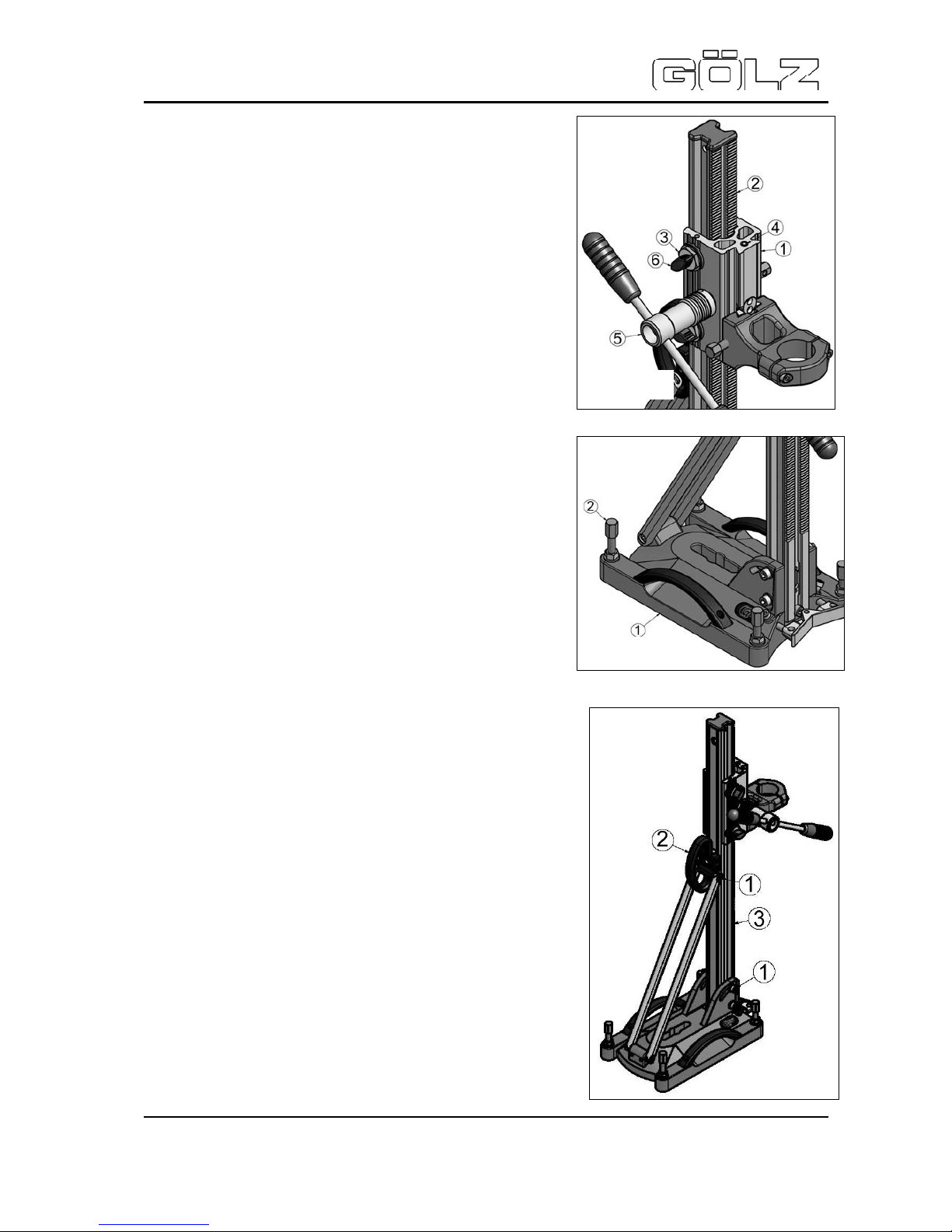
3.2.2 Vorschub
Der Vorschub (1) sorgt f ür eine stabil e Führung auf dem Holm
(2) während des Bohrens. Die Stell schrauben (3) aus Alumi nium dienen zum leichten Nachstellen der Führungsstopfen. Mit
Hilf e der Libelle ( 4) lässt sich das Stativ ausrichten. Das Drehkreuz (5) ist leicht v on der linken auf die rechte Seite umzustecken. Die Flügelschraube (6) dient zum bremsen und feststellen des Vorschubs. (Bild 3-2)
3.2.3 Fußplatte
Die Fußplatte (1) gibt der Bohrsäule die nötige Stabilität und
ermöglicht zudem die B efestigung in der Waagerecht en. Es gibt
zwei Möglic hk eiten den Fuß an Boden und Wand zu m ontieren:
• Schlagank er und S c hnellspannstange M12
• Vakuum platte mit Vakuumpumpe (ohne Ab.)
und Schnellspannsäule (ohne A b.).
Die Stellschrauben (2) im Fuß dienen dazu, den
Kernbohrständer in die Waagerechte zu stellen. Für die
Bodenmontage i st eine Libel le und für die Wandm ontage eine
Wasserwaage im Gerät integr iert.
Als extra Abstützung wird das Kernbohrgerät mittels einer
Schnellspannsäule zwischen Fußplatte und Decke/Wand
verspannt werden. ( B ild 3-3)
3.2.4 T ransport
Der Kernbohrständer (ohne Mot or) lässt sich leicht am Handgriff
(2) transport ieren. Der Mot or mit Schnellspannpl atte ist l eicht deund monti er bar . (Sehr hilfreich bei Wandmontage). (B ild 3-4)
3.2.5 Waagerecht / schräg stellen
Der Holm k ann stufenlos bis zu einem Wi nkel von m ax 45 Grad
eingestell t werden. Lösen Si e di e Schrauben ( 1), bewegen Sie die
Säule (3) i n die gewünschte Position und dr ehen Sie die Schr auben wieder fest.
Achtung: Vor dem verstell en des Holms (3) ist die Im busschraube
(hinter der B ohr k r onenzentrierung) unt en im Holm zu entfer nen .
3.2.6 Bohrmotor und Motorplatte
Der Motor wird mittel s einer Motorplat te oder Motorhalsaufnahme
60 mm, abhängig v om Typ des Motors, am Schlit ten montiert.
Bild 3-4
Bild 3-2
Bild 3-3
Page 12

KB 125
Bedienungsanleitung / Operating instructions / Mode d’emploi
- 12-
02951250999
5004593-02
4.0 Gebrauch des Kernbohrständers
4.1 Aufstellen
Das Aufstellen besteht aus drei Schritten
4.1.1 Fixieren
Schritt 1
Zum Fixieren des Bohrständer s gibt es zwei Möglichk eiten:
n Mittels Kordelgewindestange und Schnellspannmutter
• Schlagank er in Wand/Boden anbringen.
• Gewindestange in S c hlaganker drehen.
• Fußplatte über die G ewindestange setz en und mit der Sc hnellspannmutter fixieren.
o Fixieren mittels Vakuumplatte
(Nicht möglich auf porösen Untergrund wie Putz , Fliesen, T apeten, Linoleum).
• Untergrund egalisieren und reinigen..
• Vakuumbl oc k und Gummidichtung m ontieren. (Zubehör)
• Fuß waagerecht auf Untergrund stellen.
• GÖLZ Vakuumpumpe an Vakuumstütze anschließen.
• Nachdem Vakuum erzielt worden ist, muss die Pumpe eingeschaltet bleiben. (Das
Manometer muss im Berei c h zwischen –0,7 und -1 anzeigen, um ausreichend Vakuum z u
erzielen)
• Das Vakuum wird aufgehoben, wenn die Pumpe ausgeschaltet und die Vakuumplatte
entlüftet wird.
Als zusätzl iche Abstützung wird das Kernbohrger ät mit ei ner Schnellspannsäule zwischen F ußplatte
und Wand/Decke ver spannt.
4.1.2 Gerät w aagerecht / schräg st ellen
Schritt 2
Stellen Sie den Fuß mit Hilfe der Stellschrauben waagerecht. Für die Bodenmontage ist eine Libelle in
den Schlitten montiert worden..
4.1.3 Montage von Motor und Diamantbohrkrone
Schritt 3
• Den Vorschub in den höchsten Stand dr ehen.
• Motor mit Motorpl atte oder Motorhals montieren.
• Diamantbohrer mit eventuellem Verlängerungsstück oder QuickFix auf dem Motor
befestigen.
• Wasserschlauch zwischen Wasserhahn und Wasseranschluss des Motors anbringen.
Dann Wasserhahn aufdrehen. (Verwenden Sie kein Schmutz wasser)
• Führen Sie das Abwasser immer sicher ab, beispielsweise mit einem Wassersauger.
Kabel, S tecker und E lektrizität dürfen nie mit Wasser in Berührung kommen. Beim Überkopfbohren sollte man immer einen Wassersammelring benutzen. Bei Horizontalbohrungen ist dies zu em pfehlen.
Kontrollieren Sie, ob alles richtig montiert ist und beachten Sie die Sicherheitshinweise.
Page 13

KB 125
Bedienungsanleitung / Operating instructions / Mode d’emploi
- 13-
02951250999
5004593-02
5.0 Wartung und Pflege
5.1 Präventive Wartung
Im Allgemeinen gilt, dass regelmäßige Wartung (prüfen, reinigen, schmieren) sich positiv auf die
Sicherhei t und Lebensdauer der Maschine auswirkt.
Beim Reinigen von angekuppelten Maschinen,
elektrische Teile abschir men
Der Ständer braucht wenig Pflege. In Tabelle 5-1 wird angegeben wann eine Wartung empfohlen wird.
Hierbei wird aber nur eine I ndikati on der W artungsinterwall e gegeben. Die Arbei ten, die unabhängi g
hiervon verr ichtet werden können, werden später i n diesem Kapitel besprochen.
Intervall Aktivität Bemerkungen
Nach jedem E insatz
Reinigen von:
• Verbindungen
• Anschlusspunkten
• Gummis
Wasser, T eflonspray
Wasser
Wasser
Wöchentlich Allgemeine Kontrolle auf:
• Beschädigungen
• Anschlusspunkten
Reinigen
Kontrolle Führungsstopfen
• Justierung
• Verschleiß
Einstellen und evt. ersetzen
Monatlich Einf etten von:
• Gummis
• Drehachse
• Stellschrauben
Vaseline
Fett
Fett
Jährlich Generalüberholung Durchzuführ en von Fachkr äften
Wenn der S tänder längere Zei t nicht benutzt wird, bitte staubfrei lagern.
5.2 Führungsstopfen einstellen und ersetzen
5.2.1 Führungsstopfen einstellen
Durch konstante Reibung zwischen den Führungsstopfen
(1)
und Führungsschienen, werden die Blöcke verschleißen. Dies
wird auf die Dauer eine niedrigere Stabilität zur Folge haben.
Das Spiel kann man auf die nachfolgende Weise wieder
beheben:
1.
Schraube (3) m it dem Inbusschlüssel ein wenig lösen
2. Stopfenhalter (2) eindr ehen bis das Spiel beseitigt ist
3. Schraube (3) wieder festdrehen (Bild 5-1)
-
Page 14

KB 125
Bedienungsanleitung / Operating instructions / Mode d’emploi
- 14-
02951250999
5004593-02
5.2.2 Führungsstopfen ersetzen
Wenn di e Führungsstopfen (1) nicht m ehr nachzustell en sind, müssen sie ersetzt werden. Entfernen
Sie di e zwei Z ylinderk opfbolzen (3) und Stel lbolzen (2) und ersetzen Sie die F ührungsstopfen durch
neue. (Bild 5-1)
5.3 Abtransport von Materialien
Wi r m öchten Si e darauf hinweisen, dass im Z usamm enhang mi t den Umweltv or schrif ten, die Entsorgung von zu er setz enden Teilen nach den vorgeschriebenen Regel n geschehen muss.
Wenn das Ersatzteil nicht durch die Firma GÖLZ ersetzt wird, muss die Entsorgung durch die
zuständige Instanz geregelt werden. Alle dadurch entstandenen Kosten gehen auf Rechnung des
Kunden.
6.0 Garantie
6.1 Zeitraum
Für die Kernbohr ständer gewähren wir 12 Monat e Garanti e ab Tag der Lieferung. Garanti eansprüche
müssen mit den Rec hnungskopien belegt werden.
6.2 Umfang
Währ end der Garantiezei t beheben wir kostenlos Material- und Fertigungsfehler, nac hdem der
Schaden v on GÖLZ beurtei lt wurde. Transport- und Reisekosten gehen zu Lasten der Kunden.
Der Garanti e er lischt wenn :
• die Maschi ne fehlerhaft bedient oder angeschlossen wurde
• die Maschi ne über lastet wurde
• die Maschi ne z weckent fremdet eingesetzt wurde
• bei nachgewiesener unzureichender Wartung
• die Bet r iebsanleitung und Sicherheitsempfehlungen nic ht beachtet wurden
• die Maschi ne von unbef ugten Personen benutzt wurde
• die Maschi ne mit Fr emdteil en r epar iert wurde.
• die Kodierung nicht mehr erkennbar ist oder ent fernt wurde
• Mängel/ S c häden dur c h B r and oder Transport entstanden sind
6.3 Bestimmungen
Bei Bedarf werden Sie aufgef ordert, die Maschine zur Beurteil ung der Schäden zurückzuschicken.
Transport- und Reisekosten gehen z u Lasten der K unden.
Bitte teilen Sie uns Ihre Beanstandungen schriftlich mit. Achten Sie darauf, dass die Maschine
transportgerecht verpackt wi r d, um Transportschäden vorzubeugen.
Page 15

KB 125
Bedienungsanleitung / Operating instructions / Mode d’emploi
- 15-
02951250999
5004593-02
1.0 Introduction
1.1 Preface
The purpose of t his operati ng m anual i s to give you instr ucti ons about t he saf e usage of t he core dr ill
rig. When preparing this manual is was assumed that the user
of the machine has got adequate
experience in this field. The manual includes the most important information as to setting up the
machine, operating it as well as to dismounting and maint aining the m ac hine.
1.2 Validity
This operati ng manual is ex c lusively valid for the usage of the core drill rig.
1.3 Norms
This operati ng manual is conform to CE r egulations. See at tached supplier’s declaration.
2.0 General safety
2.1 Introduction
In order to prev ent any dangers such as electri c schocks, f ire or injuri es, please respect the following
safety precautions. Please take careful notice of this information and follow the piec es of advice.
2.2 Basic rules
Prevention of electric scho cks
A water-cool ed electr ic mot or with edge ground may only be used if the whole system i s completel y
grounded and is connected to t he power supply system v ia a faultlessly working ground protection
system (FI B ox or PCRD). T he c utoff c ur r ent of the ground protection m ay not exceed 30mA . Test the
system befor e y ou start working with it.
A doubly insul ated water-cool ed elect ric m otor wit hout edge groundi ng may onl y be connected t o the
power supply system with a special CE E c onnec tor 16 – 12 h via an isolating transformer . The special
CEE plug (appli cable f or bei ng used wit h FI-Box or i solati ng transfor mer) m ay not be remov ed or be
replaced by any ot her plug. If y ou ar e in doubt, please cont ac t a expert qual ified in this field
Water and el ect ricity
Make sure that the connection of the water hose doesn’t drip or leak or that the hose can even
disconnect. W hen drilling or sawing above your head the cooli ng water should always be taken into
account. W hen drilling abov e your head always use a water retention ring. When drilling in a wall a
water retention r ing is rec omm ended. Make al ways sure that the cool ing water is l ed away safely, f or
example by using a wet vac . Cable, plug and electricity may not come into c ontact with water.
Page 16

KB 125
Bedienungsanleitung / Operating instructions / Mode d’emploi
- 16-
02951250999
5004593-02
Be always attentive
Pay attention to your work, use your mind and only work with t he machine when you are concentrated.
See that, at any tim e, you ar e able to stop t he mot or as quickl y as possible. Don’t use m achines you
can’t switch on or off.
2.3 Personal protection
Wear suitable work clothes
Don’t wear any clothes which are hangi ng loosely and don’t wear any jewell ery. These things can get
between parts which are f ree to m ov e. W hen worki ng outdoor we recom mend t o wear rubber glov es
as well as shoes with grip sole. If you hav e got long hair, wear a hai r - net.
Make use of person al protection means
Wear a helm et agai nst f al l ing obj ect s, gl ov es i n order t o prot ect y ourself agai nst poi nt ed parts as well
as safety glasses to protect yourself against f alling stones or f lying sparks. W ear a respirator m ask
when doing work with high formation of dust. Ear protection is recommended if there is a noise level of
80 to 85 decibel ( A ) , ear protecti on is compulsory t her e is a noise lev el of m or e than 85 decibel (B) !
2.4 Machines
Care of tools
Keep your tools sharp-edged and clean ensuring better and safer work. Keep to the maintenance
instructions. Make sure that the handles are dry and free from oil and grease.
Check if the machine is damaged in some way or ano t her
Check if all parts free to move function faultlessly, if they aren’t jammed, if they are broken or mounted
correctly and check if all other conditions for a faultless functioning of the machine are given.
Damaged parts have to be replaced or r epaired in a workmanlike manner by admitted expert staf f.
Use of accessoires and auxiliary means
Only use accessories and aux iliary means which are mentioned in the operating manual or catalogue.
The use of other accessories or auxiliary means can lead to i njuries.
Cable/Extension cable
Only use undam aged ex tensi on cabl es which are appropri at ed f or bei ng used outdoor and m ak e sure
that the cross section of the conductor is adequate.
Unroll a cable drum completely in order to prevent it from overheati ng. Never t ak e the machine by the
cable to carr y it and don’t use the cabl e to pull the plug out of the socket. Protect the cable against
heat, oil and sharp edges.
Repair of el ect rical equip ment
Electrical equipment must correspond to the applicable safety regulations.This is why repairs may
exclusi vely be ef fected by admitted ex pert staff qualif ied in this f ield as otherwise there would be a
danger for t he user.
2.5 Environment
See that you r working environment is clean and tid y
An untidy working environment can lead to accidents. Do not accept that unauthorized people
(childr en) tr espass your working env i ronm ent or t hat t hey can run t he m achi nes. Mak e sure that while
you are drilling or sawing the bored or sawn parts are collected or supported (in particular when drilling
or sawing in soils or i n the ceili ngs). K eep the equipment in safe custody when you have finished work
Page 17

KB 125
Bedienungsanleitung / Operating instructions / Mode d’emploi
- 17-
02951250999
5004593-02
and keep them, if possible, in a locked room (so that children cannot reach them).
Care for the whole worki ng environ ment
See to it that there is enough light. Be careful where you put the cable, the conductors and the
reinforcing iron. Never use electrical tools in a damp environment (rain) or close to combustible
material.
Take care that your working environment is safe
Make sure t hat the equipment and the corresponding tools are safely fixed so that they cannot loosen.
Check, bef ore the machines are switched on, whether al l the keys and other auxiliary means have
been remov ed. Make sure that bl ade guards ar e safely mounted and al ways stay away from mov i ng
parts. Avoid an abnormal posture and keep your balance.
2.6 Explanation of the used symbols
In the operating manual, in addition to the chapter General Safety , the fol lowing three sybols
are used in order to warn the user.
Disregarding this warning means risk of injury.
Disregarding this warning can lead to breakdown of the machi ne.
Tip: Regarding means more effi c ient operation.
Page 18

KB 125
Bedienungsanleitung / Operating instructions / Mode d’emploi
- 18-
02951250999
5004593-02
3.0 Description
3.1 Principal components
In figure 3-1 the most important pr incipal components are shown. For detailed drawing of the
core drill rigs refer to the drawing of explosion.
The core drill rig is m ade of 6 principal components:
1. Carriage / F eed
2. Column / Arbor
3. Dowel base
4. Support jack
5. Swan neck motor adapt er
6. Cross handle
3.2 Function
3.2.1 In general
The adjustable core drill rig emanates from the producti on run of core drill rigs made for drilling with
diamond drills. These drills are adapted for dr illing in concrete, asphalt and rock. The f uncti on of the
drill rig is to bring the drilling machine into position and to guide i t during t he drilling. Regarding the
maximum diameter for these drill rigs see the technical data sheet.
The core drill rig may not be used
for appl ications other t han those
menti oned above!
Page 19

KB 125
Bedienungsanleitung / Operating instructions / Mode d’emploi
- 19-
02951250999
5004593-02
3.2.2 Feed
The feed (1) provides for a stable gui de of the arbor during the
drilling. The adjusting screws (3) made of alum inium serv e f or
slight adj ustment of the gui de plugs. B y means of the lev el (4)
it is possible t o adjust the support. The cross handle (5) can
easily be switched from the left to the right side. The wing
screw (6) serves f or br ak ing and fixing the feed. (Bild 3-2)
3.2.3 Base plat e
The base plate (1) provides the drill column with the required
stability and m akes it, in addition, possible to fix the column
horizontally. There are two possibilities to mount the base onto
the soil and the wall:
• Wedge anchor and quick clamping rod
• Vacuum hold down and vacuum pump (without fig.)
and quick cl amping column (without fig.).
The adjusting screws (2) in the base serve to put the core drill
rig in a hori zontal positi on. For m ounti ng it on t he soil there is
a level integrated in the unit, for mounting it on the wall a
water-level.
For additional support the core drilling machine is clamped
between the base plate and the cei ling or wall by means of a
quick cl amping column. (Bild 3-3)
3.2.4 T ransport
The core drill rig (without motor) can easily be transported by
means of the handle (2).The motor with quick clamping plate
can easily be m ounted and dismounted. (This is a ver y helpful
when mounting i t onto the wall). ( Bild 3-4)
3.2.5 Position – horizontal / oblique
The arbor is continuously adjustable up to an angle of 45
degrees. Loosen the screw (1), m ove the column (3) to put it
into the desir ed posi tion and fix the screws again.
Note
: Before adjusting the arbor (3) the socket head screw
under the arbor (behi nd the centri ng devi ce for the drill bit) has
to be removed.
3.2.6 Drill rig motor and motor plate
The m otor is mounted to the carr iage by means of a motor plat e
or a motor nec k holding fixture 60 mm, dependi ng on the type of
motor.
Bild 3-4
Bild 3-3
Page 20

KB 125
Bedienungsanleitung / Operating instructions / Mode d’emploi
- 20-
02951250999
5004593-02
4.0 Usage of the core drill rig
4.1 Setting up
The core drill rig is set up in three steps
4.1.1 Fixing
Step 1
There are two possibilities to fix the drill rig:
n By means of c or d threaded rod and a quick clamping nut
• Fixi the wedge anchor to t he wall/soil
• Turn the threaded rod into the wedge anchor
• Install the base plate above the threaded rod and fix it by means of the
• quick c lamping nut
o Fixing by means of the vacuum hold down
(Not possible on porous ground such as stucco, floor tiles, wall paper, linoleum).
• Lev el the ground and clean it.
• Mount the vacuum block and the rubber seal (ac c essori es).
• Put the base horizontally on the ground,
• Connect the GÖLZ vacuum pump to the vac uum support,
• After a vacuum has been created, the pump has to stay switched on (The manomter
must indicate between –0,7 and –1 in order to create sufficient vacuum),
• The vacuum is removed as soon as the pump is switched off and the air is removed
from the vac uum hold down.
As additional support t he core dr ill machine is clamped between the base plate and the wall/ceiling by
means of a quick clam ping column.
4.1.2 Posi t ioning of the machine – horizontal / oblique
Step 2
Put the base in a horizontal positi on by using the adjusti ng screws. For mounti ng on the soil a l evel
has been mounted int o the carriage.
4.1.3 Mounting of the motor and the diamond drill bit
Step 3
• Turn the feed to the highest l evel-
• Mount the m otor with motor plate or motor neck.
• Fix the diamond drill to the motor by using an extension if necessary or by using QucikFix.
• Place t he water hose between the water tap and the water supply of t he motor. T hen turn
the water tap on. (Do not use any waste water)
• Lead the waste water always safely away, f or ex ampl e by using a wet v ac. Cabl e, plug and
electri ci ty shoul d never get i n cont act with water. When drilling above your head you should
always use a water retention ring. W hen dr illing horizontally it is recommendable to use such
a ring.
Check if everything is mount ed c or r ec tly and follow the safety r egulations.
Page 21

KB 125
Bedienungsanleitung / Operating instructions / Mode d’emploi
- 21-
02951250999
5004593-02
5.0 Maintenance and care
5.1 Preventive maintenance
Generally speaking you can say that maintenance at regular intervalls (checking, cleaning and
greasing the mac hine) has a positive effect on the safety and the life time of the machine.
When c leaning machines which are coupled on shield any electri c al parts
The ri g doesn’t need much care. In tabl e 5-1 it is indicat ed when a maintenance is recom mended.
However, onl y t he int ervall s of m aint enance are i ndi cat ed. T he work which can be done irrespectiv ely
of that will be discussed later in this chapter.
Interval Activity Notes
After eac h
operation
Cleaning of the:
• connections
• connection points
• rubbers
Water, tef lonspray
Water
Water
Once a week General check for:
• demage
• connection- points
Cleaning
Checking for guide plugs
• adjustment
• wear
Adjusting and, if necessary,
replacing
Once a mont h Greasing of :
• rubbers
• rotation axis
• adjusti ng screws
Vaseline
Grease
Grease
Once a year General overhaul To be effected by ex per t staff
If t he r ig isn’t used for a longer tim e, store it i n a dust- free environment .
5.2 Adjustment and replacement of guide plugs
5.2.1 Adjustment of guide plugs
Due to constant f riction between the guide plugs (1) and the
guide tr acks t he bloc ks are worn. In t he l ong run thi s will result
in less stability.
1. Loose the screw (3) a little with a socket wrench
2. Turn in the plug holder (2) until there i s no play
anymore
3. Fix the screw(3) again (Bild 5-1)
-
Page 22

KB 125
Bedienungsanleitung / Operating instructions / Mode d’emploi
- 22-
02951250999
5004593-02
5.2.2 Replacement of gui de plugs
When t he guide plugs (1) cannot be adusted anym ore, they have to be r eplaced. Remov e the two
cylinder head bolts (3) as well as the correcting bolts and repl ac e the guide plugs by new ones.
(Bild 5- 1)
5.3 Removal of material
We would li k e to point out t hat – in connect ion with the environmental regulations – parts which are to
be replaced have to be disposed of acc or ding to the correspondi ng r egulations.
If the spare part i s not repl aced by G ÖLZ , i t s disposal has to be arranged by the com pet ent aut hori t y.
All char ges which are c aused hereby ar e for the account of the custom er .
6.0 Guarentee
6.1 Period
For the core drill rigs a guarantee of 6 months is issued from the day of delivery. Claims under
guarantee have to be prov ed by br inging a copy of the invoice.
6.2 Outline
During the guarant ee period material defects and defect s of fabricat ion are repaired free of charge
after the claim has been estimated by the GÖLZ. Transport costs and travelling costs are f or the
account of the customer.
The guarantee ex pires when:
• the machine was operated or connected inaccccurately
• the m ac hine was overcharged
• the m ac hine was used for purposes other than intended
• in case of proved unsufficient mai ntenance
• the operating manual and the recommendations as to the safety regulations were not
adhered to
• the m ac hine was used by unauthorized people
• the m ac hine was repaired with parts other t han intended
• the encodi ng was removed or coul dn’t be identified any m or e
• Deficiencies or damages were caused through fire or transport
6.3 Regulations
If requi red y ou are asked to send the m ac hine bac k so that t he dam ages can be estim ated. Transport
costs and trav elling costs are for the account of the custom er .
Please let us know your com plai nts in writ ing. T ake care that the machi ne is so packed that it can be
transported safely in order to pr event any damage in transit .
Page 23

KB 125
Bedienungsanleitung / Operating instructions / Mode d’emploi
- 23-
02951250999
5004593-02
1.0 Introduction
1.1 Préambule
Cette notice d’utilisation a pour but de vous aider à utiliser le bâti de carottage GÖLZ KB 125 en toute
sécurité. Cet te not ic e a été élabor ée par des utilisateurs avertis. Cette notice contient les informations
essentielles pour l a mise en place, l’utilisation, le démontage et l’entretien de la machine.
1.2 Validité
Cette noti c e c onc er ne exclusivement le bâti de carot tage GÖLZ KB 125.
1.3 Normes
La notice est conforme aux dispositions CE. Voir attestation de conformité jointe.
2.0 Consignes de sécurité
2.1 Introduction
Afi n d’éviter él ectrocution, i ncendie ou autre blessures veiller au respect des consignes de sécuri té
suivantes. Lire soigneusement c es inform ations et suivre les conseils.
2.2 Règles de base
Prévenir les électro cutions.
Un moteur él ectrique avec prise de terre ne doit être utilisé que sur un réseau él ectrique disposant
d’une mise à la terre en parfait état de fonctionnem ent. L’ensemble du système doit être mis à la terre
et raccordé ex clusiv ement par un disjoncteur di ff érentiel (PCRD) en parf ait état de fonctionnem ent.
La protect ion du dif f érenti el ne doit pas exc éder 30 mA. Testez l e système av ant de c omm encer l es
travaux.
Un mot eur élec tri que refroidi à eau à doubl e i solat ion ne doi t être r accor dé au réseau élect ri que que
par une prise codée CEE 16-12h et un transformateur (1:1). La prise codée CEE (adaptée pour
l’utilisation avec un boîtier de protection FI ou un transformateur) ne doit pas être démontée ou
remplac ée par une autre prise. En cas de doute prendr e c onsei l auprès d’un électri c ien qualifié.
Eau et électri cité.
S’assurer de l’ét anchéité du raccord d’eau, il ne doit pas y avoi r de fuit e et les raccords ne doi t pas
pouvoir se détacher. Lors du carottage ou sciage au plafond, il faut toujours surveiller l’eau de
refroidissement. Pour le carottage au plafond utiliser un anneau de récupération d’eau. Ceci est
également recommandé pour le carottage au mur. Evacuer l’eau de refroidissement toujours en
sécurité, par ex em pl e avec un aspi rat eur à eau. Les câbl es et pri ses élect ri ques ne doivent en aucun
cas entrer en contact avec l’eau.
Page 24

KB 125
Bedienungsanleitung / Operating instructions / Mode d’emploi
- 24-
02951250999
5004593-02
Soyez toujours vigilant
Soyez attentif à votre travail et n’utilisez la m achine que si vous êtes concentré. Veillez à être toujours
en mesure de couper rapidement le moteur. N’utilisez pas une machine qui ne dispose pas d’un
interrupt eur en bon état de fonct ionnement.
2.3 Protection des personnes
Portez les vêtements de t ravail adaptés
Ne portez pas de v êtements f lottant s ni de bijoux . Ceux-c i pourraient être happés par des pièces en
mouvement. Il est recommandé de porter des gants en caoutchouc et des chaussures antidérapant es.
Mettez l es cheveux longs dans un filet.
Utilisez les protections personnelles
Portez un casque pour prév eni r d’év entuel les chutes d’objet s, des gants pour la protec tion cont re les
coupures et des lunettes pour la protection des yeux contre d’éventuelles projections. Portez un
masque dans des envir onnements poussiéreux. Il est recommandé de porter un casque auditif à parti r
d’un niveau sonore de 80 dB (A), au-delà de 85 dB ( A ) le port d’un casque est obligatoire!
2.4 Machine
Entretien de l’outillage
Afin de tra vaille r e n toute sécurité veillez à d isposer d’ou tils en bon état de fonctionnement. Respectez
les consignes de sécurité. Veillez à ce que les poignées et organes de com mande soient exem pts
d’huile et de gr aisse.
Vérifiez l a machine sur d’évent uels défauts
Vérifiez le bon fonctionnement des pièces en mouvement, cel les-ci ne doivent pas coincer, ne doivent
pas être cassées et doivent être montées correctement. Les pièces défectueuses doivent être
remplac ées ou réparées par du per sonnel qualifié.
Utilisation d’accessoires
N’utilisez que des accessoires préconisés dans la notice d’utilisation ou le catalogue du fabricant.
L’utilisation d’accessoires non adaptés peut conduire à des blessures.
Câbles/rallonges
N’utilisez que des rallonges ne parfait état avec des sections adaptées à la puissance électrique
requise pour le m oteur. Les rallonges sur enroul eur doivent être entièrem ent déroulées afi n d’évit er
les surchauff es. Ne portez jam ais la machi ne par le câble électr ique, ne retirez jamai s une prise en
tirant sur le câble. Prot égez le câble contr e la chaleur, les graisses et les angles vi fs.
Réparation d’appareils électriques
Les appareils élect ri ques doivent répondre aux norm es de sécurité en v i gueur. Pour év i ter les risques
à l’utilisateur, les réparations ne doivent être effectuées que par un électr icien qualifié.
2.5 Environnement
Veillez à disposer d’un lieu de travail propre
Un lieu de travail désordonné peut conduire à des accidents. Ne tolérez pas la présence de
personnes non autorisées sur le chantier (enfant s). Veillez à ce que, lors de travaux de sciage ou de
carottage, les parties sciées ou carottées soient sécurisées, (en particulier lors de travaux de
carottage ou de sciage au sol ou au plafond). A l a f i n des travaux, sécurisez l es m achi nes contre une
utilisation intempestive et conservez-les si possible dans une pièce fermée à c lé (hors de portée des
enfants).
Page 25

KB 125
Bedienungsanleitung / Operating instructions / Mode d’emploi
- 25-
02951250999
5004593-02
Veillez à l’environnement de votre poste de travail
Veillez à un bon éclai r age. Repérez la position des câbles, conduites et ferraillages dans les parties à
carotter. N’utilisez jamais de l’outillage électrique dans un environnement humide (pluie) ou à
proximité de produits inflammables.
Sécurisez votre poste de travail
Fix ez les appareils et accessoires de manière sûre, afin qu’i ls ne puissent pas se détacher. Avant la
mise en route, vérif i ez que t outes l es clés et out il s utilisés pour la fi x ati on ont ét é ret ir és. Véri f i ez que
les protecti ons ont bien été montées et m aintenez-vous touj ours à distance de sécurité par rapport
aux pièces en mouvement. Evitez des positions de travail périlleuses et veillez à un bon équilibre.
2.6 Symboles utilisés
La notice d’utilisation utilise, en plus du chapitre généralité concernant la sécurité, les 3 symboles
suivant pour infor mer l’utilisateur.
Le non respect de cette consi gne engendr e un risque de blessure.
Le non respect de cette consi gne engendr e une dest r uc tion de la m ac hine.
Conseil: l e sui vi de cette consigne permet une utilisation plus efficiente de la machine.
Page 26

KB 125
Bedienungsanleitung / Operating instructions / Mode d’emploi
- 26-
02951250999
5004593-02
3.0 Description
3.1 Composants principaux
La photo 3-1 mont re les princ ipaux composants. V ous trouv erez une i nform ati on plus détaillée sur le
dessin éclaté.
Le bâti de carott age est composé de 5 pi èces principales:
1. Chariot / avance
2. Colonne / guide
3. Pied à cheviller
4. Renfort
5. Collier réception
6. Volant
3.2 Fonctions
3.2.1 Généralités
Le bâti de carottage réglable est desti né au carottage avec des outils diamant. Les outils diamant
servent à carotter le béton, l’asphalte ou la pierre. La fonction du bâti est de m ettre le moteur en
position et assurer l e guidage lors du carottage. Vous trouverez le Ø de carottage m axim al dans la
fic he technique.
Le bâti de carot tage n’est pas adapté à d’autres applications que celles
décrite s ci-dessus!
Page 27

KB 125
Bedienungsanleitung / Operating instructions / Mode d’emploi
- 27-
02951250999
5004593-02
3.2.2 Avance
Le chariot d’av ance assure le guidage (1) sur la colonne (2)
pendant le carottage. Les vis de réglage en aluminium (3)
servent au r églage des glissoirs, le niveau à bulle (4) perm et le
réglage du bâti . Le volant (5) peut être monté des 2 côtés du
chariot. La vis papillon (6) sert au blocage du chariot d’avance.
(Bild 3- 2)
3.2.3 Socl e
Le socle (1) donne l a rigidité au bât i et permet la f ixati on de
celui-ci en position verticale. Il y a 2 possibilités de fixer le
socle au sol ou au mur:
Cheville et tige filetée M12
Socle ventouse avec pompe à v ide (sans illustration)
Les vis de régl age (2) dans le socle serv ent à régler le bâti à
l’horizontale. Il y a un niveau à bulle pour le montage à
l’horizontale et à la verti c ale.
Les renforts servent à stabiliser socle et colonne. (Bild 3-3)
3.2.4 T ransport
Le bâti de car ottage (sans moteur) peut être tr ansporté par la
poignée (2). Le moteur peut être monté ou démonté rapidem ent
par le systèm e de f i x at ion S TS. (T rès prati que pour l e m ont age
au mur). ( B ild 3-4)
3.2.5 Réglage inclinaison de la colonne
La colonne peut êtr e réglée de 45 à 90°. Desserrez les vis (1),
incli nez la colonne (3) dans la position souhaitée et resserrez
les vi s.
Attenti on: av ant l e réglage de l a colonne ( 3) il faut démont er la
vis CHc (en bas de la colonne).
3.2.6 Monteur de carottage et plaque de fixation monteur
Le moteur est monté au moyen d’une plaque moteur ou d’un col
de cygne Ø 60mm.
Bild 3-4
Bild 3-3
Page 28

KB 125
Bedienungsanleitung / Operating instructions / Mode d’emploi
- 28-
02951250999
5004593-02
4.0 Utilisation du bâti carottage
4.1 Mise en place
La mise plac e se fait en 3 étapes
4.1.1 Fixat ion
Etape 1
Pour fixer le bâti il y a 2 possibilités :
n Au moyen d’une tige d’ancrage et d’un écrou à serrage rapi de
• Fixer la cheville dans le sol ou le mur.
• Visser la t ige d’ancrage dans la cheville.
• Poser le socle sur le pied et f ixer avec l’écrou.
o Fixation av ec la plaque ventouse
(Ce moyen de fixation n’est pas utilisable sur crépis, carrelage, papier peint, linoleum).
• Nettoyer l e support qui doit être plan.
• Monter le kit v ide et le joint en caoutchouc. ( ac c essoir e)
• Poser le soc le.
• Raccorder la pompe à vide GÖLZ C 10.
• Après avoir fixé la pompe à vide celle-ci doit rester branchée. (le manomètre doit se
trouver dans une plage de - 0,7 -1 bar de dépression afin d’assurer la fixation)
• La fixation s’arrête lorsque la pompe est coupée et le socle mis à l’air am biant.
Pour une sécurit é supplément aire, la f ix ati on du bâti doi t êtr e assurée par un étai entre l e socle et le
plafond.
4.1.2 Réglage de l’inclinaison de la colonne
Etape 2
Régler l e socle à l ’hori z ontal e au m oyen des v i s de régl age. Ut iliser le niveau à bull e du char iot pour
ce réglage.
4.1.3 Montage du moteur et de la couronne diamant
Etape 3
• Remonter enti èr ement le chariot.
• Monter le moteur avec la plaque de fixati on.
• Monter la couronne di amantée sur le moteur.
• Raccorder l’arr iv ée d’eau sur l e robinet du m oteur. Ouv ri r le robinet d’eau. (n’utiliser que
de l’eau claire)
• Evacuer toujours correctement l’eau de carottage, par exemple avec un aspirateur à
boues. Câbles, prises élect riques et électric ité ne doiv ent jamais entrer en contact av ec
l’eau. Pour l e carottage au plafond utiliser exclusiv ement un moteur autorisé pour cette
opération avec un anneau récupérateur d’eau. L’anneau de récupération d’eau est
fortement recom mandé pour les carott ages aux murs.
Vérifiez si tout est c or r ectement monté et respectez les consignes de sécurité.
Page 29

KB 125
Bedienungsanleitung / Operating instructions / Mode d’emploi
- 29-
02951250999
5004593-02
5.0 Entretien
5.1 Entretien préventif
En règle génér ale un entret ien régul ier ( v érif icat ion, nettoyage, graissage) augment e la sécuri té et l a
durée de vie de la machine.
Pour les opérati ons d’entr etien et de nettoyage retirez l’alim entation électrique de la
machine
Le bâti ne nécessite qu’un ent r etien mi nimum. Le tableau 5-1 fournit les indications sur les i ntervalles
d’entretien r ec ommandés. La descri ption des travaux à effectuer est décrite plus loi n.
Intervalle Activité Remarque
Après chaque
utilisation
Nettoyage de :
• Raccords
• Point s de fixat ion
• Caoutchouc
Eau, spray téflon
Eau
Eau
Toutes les semaines Contrôle général de :
• Défaut s éventuels
• Point s de fixat ion
Nettoyer
Contrôler Glissoirs
• Régler
• Usure
Régler, l e c as échéant r emplacer
Mensuel Graissage de :
• Caoutchouc
• Arbre d’avance
• Vis de régl age
Vaseline
Graisse
Graisse
Annuel Entret ien général Par un atelier spécialisé
En cas de non-utilisation prolongée, stocker la machine dans un endroit sec à l’abri de la poussière.
5.2 Réglage et remplacement des guides du chariot
5.2.1 Réglage des glisso irs
Par la f ri ct ion per m anente des gl issoirs (1) et de la colonne, il y
a usure des blocs glissoirs. A terme ceci aura un effet sur la
stabilité de la machine. Le jeu peut être réglé selon la
description c i-après :
1. Desserrer la v is CHc (3) au moyen d’une clé Allen
2. Régler l e support du gli ssoir (2) jusqu’à la suppression
du jeu
3. Resserrer la vi s (3) (Bild 5-1)
-
Page 30

KB 125
Bedienungsanleitung / Operating instructions / Mode d’emploi
- 30-
02951250999
5004593-02
5.2.2 Remplacement des glissoirs
Lorsqu’il n’est plus possible de régler l es glissoirs (1) (usure total e), il faut l es changer. Retir er les 2
vi s (3) ainsi que l es supports de glissoir (2) et remplacer l es glissoirs usés par des glissoirs neufs.
(Bild 5- 1)
5.3 Recyclage des matériaux
Nous attir ons votre attention qu’il c onvient de respecter les règles du respect de l’environnement pour
le recyclage des pièces rempl acées.
Lorsque la pièce n’est pas remplacée par GÖLZ, le recyclage doit se faire par le responsable de
l’opération. Le client est responsable du recyclage des pièces et en supporte les coûts.
6.0 Garantie
6.1 Durée
Le bâti de carot tage est garanti 12 Mois à parti r du jour de la liv raison. Les demandes de garantie
devront être accompagnées de l a facture d’origine.
6.2 Conditions
Pendant la période de garantie nous remplaçons gratuitement pièces et main d’œuvre après expertise
par les ateliers GÖLZ. Les déplac ements et coûts de transport sont à la charge du client.
La garantie est caduque lorsque :
• la machine n’a pas été correctement utilisée ou branchée
• la machine a été utilisée en surcharge
• la machine n’a pas été utilisée pour sa destination
• la machine n’a pas été entretenue c or r ec tement
• les consignes de la not ice n’ont pas été respectées
• la machine a été utilisée par du personnel non qualifié
• la machine a été réparée avec des pièces autres que cel les d’origine.
• Le marquage de type n’est plus lisible ou a été enlevé
• Des défauts sont survenus suite à un incendi e ou un transport
6.3 Consignes
En cas de nécessité v ous dev ez r etourner la m ac hine c hez l e f abri cant dans le but de la contrôler sur
d’évent uels défauts. Frais de déplacement et transport sont à la char ge du c lient.
Veuillez formuler votre demande d’i nterventi on par écrit . Veillez au bon emballage de la m ac hine afin
d’éviter les dégâts lors du transport.
Page 31

KB 125
Bedienungsanleitung / Operating instructions / Mode d’emploi
- 31-
02951250999
5004593-02
7.0 Verschleißteile / Wearing parts / Pièces d’usure
Verschleißteile sind Teil e, die bei bestimmungsgemäß em Gebrauch der Maschinen einer bet riebsbedingten A bnutzung unterl iegen. Die Verschl eißzeit ist nicht einheitlich definierbar, sie differiert nach
der Einsatzintensität. Die Verschleißteile sind gerätespezifisch entsprechend der Betriebsanleitung
des Herstellers zu warten, einzustellen und ggf. auszutauschen. Ein betriebsbedingter Verschleiß
bedingt kei ne M ängelansprüche.
• Vorschub- und Antri ebsel emente wie Zahnstangen, Zahnräder, Ritz el, Spindel n,
Spindelmuttern, S pindellager, Seile, K etten, Kettenr äder , Riemen
• Dichtungen, K abel, Schläuche, Manschetten, Stec ker, Kupplungen und Schalter für
Pneumatik, Hydraulik, Wasser, Elektrik, Kraftstoff
• Führungselemente wie Führungsleisten, Führungsbuchsen, Führungsschienen, Rollen,
Lager, Gleitschutzauflagen
• Spannelemente von Schnelltrennsystem en
• Spülkopfdichtungen
• Gleit- und Wälzlager, die nicht im Ölbad l aufen
• Wellendicht r inge und Dichtel emente
• Reib- und Überlastk upplungen, Bremsvorric htungen
• Kohlebürsten, Kollektoren
• Leichtlöseringe
• Regelpotentiometer und manuelle Schaltelemente
• Sicherungen und Leucht en
• Hilfs- und Betriebsstof fe
• Befesti gungsel emente wie Dübel, A nk er und Schrauben
• Bowdenzüge
• Lamellen
• Membranen
• Zündkerzen, Glühkerzen
• Teile des Reversierstarters wie Anwerfseil, Anwerfklinke, Anwerfrolle, Anwerffeder
• Abdichtbürsten, Dichtgum mi, Spritzschutzlappen
• Filter aller Art
• Antriebs-, Umlenkrol len und Bandagen
• Seilschlagschutzelemente
• Lauf- und Ant r iebsräder
• Wasserpumpen
• Schnittguttransportrollen
• Bohr-, Trenn- und S c hneidwerkzeuge
• Energiespeicher
Verschleißteile für diese Maschine sind in der Ersatzteilliste grau unterlegt.
Page 32

KB 125
Bedienungsanleitung / Operating instructions / Mode d’emploi
- 32-
02951250999
5004593-02
Wearing parts are the parts subject to operation-related (natural) wear during proper use of the device.
The wearing time cannot be uniformly defined, and differs according to the intensity of use. The
wearing parts must be adjusted, maintained and, if necessary, replaced for the specific device in
accordance with the manufacturer’s operating manual. Operation-related wear is not a reason for
defect c laims.
• Feed and drive elem ents such as toothed racks, gearwheels, pini ons, spi ndles, spindle
nuts, spindle bear ings, cables, chains, sprock ets, belts
• Seals, cables, hoses, pack ings, connectors, coupl ings and switches for pneumatic, hydraulic,
water, electrical and fuel systems
• Guide elements such as guide strips, gui de bushes, gui de r ails, rollers, bearings, sli ding
protection supports
• Clamping elements for quick-separating systems
• Flushing head seals
• Slide and roller bearings that do not run in an oil bath
• Shaft oil seals and sealing el ements
• Frict ion and safety clutches, braking devices
• Carbon brushes, comm utators/armatures
• Easy-release rings
• Control potentiometer s and manual switching elements
• Securing el ements such as plugs, anchors, screws and bolts
• Fuses and lamps
• Auxiliary and operating materials
• Bowden cables
• Discs
• Diaphragms
• Spark plugs, gl ow plugs
• Parts of t he r eversing starter such as the starting rope, star ting pawl, starting roller and
starting spring
• Sealing brushes, rubber seals, splash protection cloths
• Filters of all k inds
• Drive rollers, deflection rollers and bandages
• Cable anti- twist elements
• Running and drive wheels
• Water pumps
• Cut-material transport rollers
• Drilling, parting and cutting tools
• Energy storage
Wear ing parts of this machine are grey marked in t he spare parts list.
Page 33

KB 125
Bedienungsanleitung / Operating instructions / Mode d’emploi
- 33-
02951250999
5004593-02
Les pièces d’usure sont celles définies par une usure normale due à I’utilisation courante de la
machine dans l es conditions norm ales d’utilisation. La durée d’usure n’est pas définissable en terme
de tem ps, elle dépend de I’intensité d’utilisation. Les pièces d’usure sont à régler ou changer selon les
indicat ions défi nies dans la not ice d’utilisation par le fabricant de la machine. Une usure normale due
à I’utilisation de la machine ne peut faire pr étendre à une demande de garantie.
• Éléments d’entraînement, d’avance t els que crémaillères, pignons, vis sans fin
• écrous pour vis sans fin, r oulements de vis, câbles, c haînes, pignons de chaîne, courroies
• Joints, câbles électriques, flexibles, manchettes, prises de courant, accouplements et
éléments de commande pneumatiques, hydrauliques, pour eau et carburant
• Éléments de guidage tels que gli ssières, douilles de guidage, rails de gui dage, galets de
guidage, roulements, prot ec tions de guidage
• Éléments de serrage pour systèmes d’accoupl ements rapides
• Joints de touret d’injec tion
• Roulem ents à aiguilles et linéaires non en bain d’huile
• Joints spi et élément s d’étanc héité
• Em br ay age de surchar ge systèmes de freinage
• Charbons et col lecteurs
• Bagues à desserrage rapide
• Potent iomètres et éléments de commandes manuell es
• Fusibles et ampoules
• Accessoires de fonctionnem ent
• Éléments de fi xation tels que chevilles, vis et vis d’ancrage
• Sandows
• Lamelles
• Mem br anes
• Bougies d’al lumage et de préchauffage
• Pièc es du systèm e de démarrage, telles que poignée de démar r age, poulie, ressort
• Brosse joint, joint s caout c houc , bavettes anti-éclaboussement
• Fi ltres de tous types
• Poulies d’entraînement ou de r envoi et leur bandage
• Éléments anti-flottement de câbles
• Roues d’entraînement et de guidage
• Pom pes à eau
• Rouleau de convoyeurs
• Outils de carottage et de sciage
• Réservoir d’énergie
Des pièces d'usure pour cet apparei l sont soutenues gris dans le catalogue pièces.
Page 34

KB 125
Bedienungsanleitung / Operating instructions / Mode d’emploi
- 34-
02951250999
5004593-02
8.0 Ersatzteilliste / Spare parts list / Liste des pièces de rechange
So bekommen Sie schnell und richtig Ihr Ersatzteil
- für Maschine - Modell - Masch.-Nr.
- Artike lnummer - Bezeichnung des Ersatzteiles
- Anzahl der gewünschten Ersatzteile
- Wohin liefern?
- Womit liefern (Post, Eilpost etc.)?
Always indicate:
- machine/model/serial number
- item number and description of the spare part
- amount of spare parts desired
- full address
- goods to be sent by regular mail, express, etc.
Pour obtenir rapidement les pièces de rechange indiquer :
- Nº de la machine, du modèle
- Nº de l’article / description de la pièce désirée
- Nombre de pièces commandées
- Adresse de livraison
- Mode de livraison (poste, express etc...)
Page 35

KB 125
Bedienungsanleitung / Operating instructions / Mode d’emploi
- 35-
02951250999
5004593-02
Page 36

KB 125
Bedienungsanleitung / Operating instructions / Mode d’emploi
- 36-
02951250999
5004593-02
Pos Artikelnummer Menge Norm Info Bezeichnung
Description
Désignation
1 1120 080 1 Drehkreuz Cross handle Volant
2 11N 011 01 2 DIN 471 Sicherungsri ng Circlip Circlips
3 11N 018 09 2
20x28x0.3
VZ
Passscheibe Shim ring Rondelle
4 11E 013 06 1 Ri t zelwelle Long-face pinion Arbre pignon
5 11N 013 05 2
Federndes
Druckstück
Spring catch Bille de maintien
6 11N 004 03 2 2010 Gleitlager Floating bearing Palier lisse
7 11N01303 1 DIN316 M8x20 Flügelschraube W i ng scr ew Vis à ailettes
8 11E 007 04 1 Br em sst opf enhalter Break holder
Support glissoir
frein
9 11E 008 07 1 25x23 m .L. Bremsstopfen Brake plug
Bouchon de
freinage
10 11E 007 01 1 Stopfenhalt er Plug holder
Support de
glissoir
11 11E 008 02 1 25x23 o. L. Führungsstopf en Plug Glissoir
12 11E 009 07 2 6x4 Klem mstopfen Plug Pièce de serrage
13 11N 001 02 2 DIN 916 8x8 Gewindestift Set screw Vis
14 11E 008 08 2 25x16 Führungsstopfen Plug Glissoir
15 11N 003 01 1 14mm Dosenlibelle Box level Niveau à bulle
16 11E 004 40 1 Bohrschlitten Drill carriage Chariot
17 11E 011 23 1 Halter Abstützung Support
Plaque de
colonne
18 11N 008 69 2 DIN 7984 M8x10 Zylinderschraube Screw Vis
19 11E 002 50 1 55x60x900 Führungssäule Column Colonne
20 0295 000 0771 1 DIN 912 M8x30 Zylinderschraube Screw Vis
21 0282 250 0006 1 DIN 433 8,4 U-scheibe Washer Rondelle
22 11E 006 07 1 AbstützstangenhalterSupport Suppor t de renfort
23 11E 010 12 1
Führungsklemmstück
Clamping device Pièce de serrage
24 11E 014 07 2 Haltestange Grab handle Tige
25 11E 019 08 1 Handgriff Hand grip Poi gnée
26 11E 014 16 2 Abstützung Support Renfort
27 0295 000 0466 4 DIN 912 M8x20 Zylinderschraube Screw Vis
28 11E 024 09 4 M10x55 Feststellschraube Screw Vis de réglage
29 0286 570 0046 4 DIN 934 M10 Mutter Nut Ecrou
30 0282 250 0662 4 DIN 125 A10,5 Scheibe Washer Rondelle
31 11N 003 02 4 Druckstück Spring catch Patin de serrage
32 11E 010 10 1 68x20x10 Schraubblech Plate Plaque
33 0282 250 0073 2 DIN 933 8x25 Schraube Screw Vis
34 11E 001 34 1 Befestigungsplatte Dowel base Socle à cheviller
35 0295 000 0363 2 DIN 912 M10x90 Schraube Screw Vis
36 0295 000 0200 1 DIN 912 M10x70 Schraube Screw Vis
37 0267 112 5047 2 DIN 912 M6x20 Schraube Screw Vis
38 11E 019 09 1 VKP Handgriff Hand grip Poignée
39 0295 000 0787 1 DIN 912 M8x10 Schraube Screw Vis
-- 1111121 1
Cardi/Bender
Pos. 40-43
Motorkupplung kpl. Motor coupl ing cpl.
Plaque moteur
complete
40 11N 008 02 4 DIN 912 M8x35 Schraube Screw Vis
41 11E 024 29 1
Klemmschraube m i t
Spitze
Clamping screw Vis de serrage
42 11E 016 08 1 Motorplatte Mounting plate
Plaque de
réception moteur
43 0267 112 5062 1 Passfeder Key Clavette
Page 37

KB 125
Bedienungsanleitung / Operating instructions / Mode d’emploi
- 37-
02951250999
5004593-02
Page 38

KB 125
Bedienungsanleitung / Operating instructions / Mode d’emploi
- 38-
02951250999
5004593-02
Pos Artikelnummer Menge Norm Info Bezeichnung
Description
Désignation
-- 1118020
Pos. 44-47
60 mm
Motorhalsaufnahme
kpl.
Swan neck motor
adapter cpl.
Collier réception
complete
44 11N 006 19 1 DIN 557 Vierkantmutter Square nut Ecr ou
45 11E 018 06 1 Motorhalsaufnahme
Swan neck motor
adapter
Collier réception
46 11E 024 29 1
Klemmschraube m i t
Spitze
Clamping screw Vis de serrage
47 0295 000 0771 1 DIN 912 M8x30 Schraube
Screw
Vis
-- 1197900 1 Pos. 48-54 Ventilplatte kpl. Valve plate cpl.
Plaque valve
complet
48 11N 035 01 1 O-Ring O-ring Joint torique
49 11E 012 06 1 Ventilplat t e Valve plat e Plaque valve
50 11N 031 04 1 Dichtung Seal Joint
51 11N 031 07 1 1/4"x9 Gewindetülle Nozzle Bec
52 119 8805 1 Moosgummi Sponge rubber Spongieux
53 0285 300 0027 1 Spannstift Roll pin
Goupille de
serrage
54 11E 012 08 1 Ventilstange Rod Barre
55 11E 034 05 1 Moosgummi Sponge rubber Spongieux
-- 1111013 1 Pos. 56-59
BohrkronenZentrierset kpl.
Drill rig centering
device cpl.
Dispositif de
centrage
complet
56 11E 012 04 1 Zentrierstange Centering bar Tige de centrage
57 0295 000 3535 1 DIN 933 M10x30 Schraube Screw Vis
58 0282 250 0662 1 DIN 125 A10,5 Scheibe Washer Rondelle
 Loading...