

Page 1
FLOOR SAW
FS 250 B
0282 250 0958/12.05
r:\technik\techdoku\englisch\fs\250b\2000958\02822500958_02_14-12-05.indd
1
Page 2

3
GÖLZ
GmbH
Dommersbach 51
D-53940 Hellenthal-Blumenthal
Phone: (02482) 120
Telefax: (02482) 12135
CE-Declaration of Conformity
We declare, the product
FS 250 B
Name:
Manufacturer:
Type:
FLOOR SAW
GÖLZ
FS 250 B
Serial number: __________
is in conformity with the Directives
- 98/37/EC
- 89/336/EWG i.d.F. 93/68/EWG
- 2000/14/EC
as well as with the standards
- EN 13682:2001
- EN 13309:2000; EN 61000
- EN ISO 3744:1995
December,16th 2003
..................................
Chief designer
2
Page 3

Contents
1. Basic informations ............................................... 4
2. Fundamental safety instructions ........................ 4
3. Description............................................................ 9
4. Transport............................................................. 11
5. Installation and operation.................................. 12
6. Maintenance........................................................ 16
7. Troubleshooting ................................................. 19
8. Spare parts list ................................................... 21
9. Connection diagram........................................... 40
All rights reserved!
We endeavour continuously to improve the quality of our products and adapt them to the
highest technical standards. The text and gures in this operating instruction can therefore
differ from your equipment.
© Copyright
GÖLZ
3
Page 4
5
1. Basic informations
Thanks for choosing a
machine and its designated use.
The operating instruction contains important information on how to operate the machine safely, properly and
most efciently. Observing these instructions helps to avoid danger, to reduce repair costs and downtimes and
to increase the reliability and life of the machine.
The operating instruction is to be supplemented by the respective national rules and regulations for accident
prevention and environmental protection. The operating instruction must always be available wherever the
machine is in use.
This operating instruction must be read and applied by any person in charge of work with or on the machine,
such as:
- Operation including setting up, troubleshooting in the course of work, evacuation care and disposal
of fuels and consumables.
- Maintenance (servicing, inspection, repair) and/or
- Transport
In addition to the operating instructions and to the mandatory rules and regulations for accident prevention and
environment protection of the country and place of use of the machine, the generally recognized technical rules
for safe and proper working conditions and procedures must also be observed.
GÖLZ
-product. This operating instruction is designed to familiarize the user with the
FS 250 B
2. Fundamental safety instructions
2.1 Warnings and symbols
The following signs and designations are used in the manual to designate instructions of particular importance:
Information: Refers to special information on how to use the machine most efciently
Attention: Refers to special information and/or orders and prohibitions directed
towards preventing damage
Danger: Refers to orders and prohibitions designed to prevent injury or extensive
damage
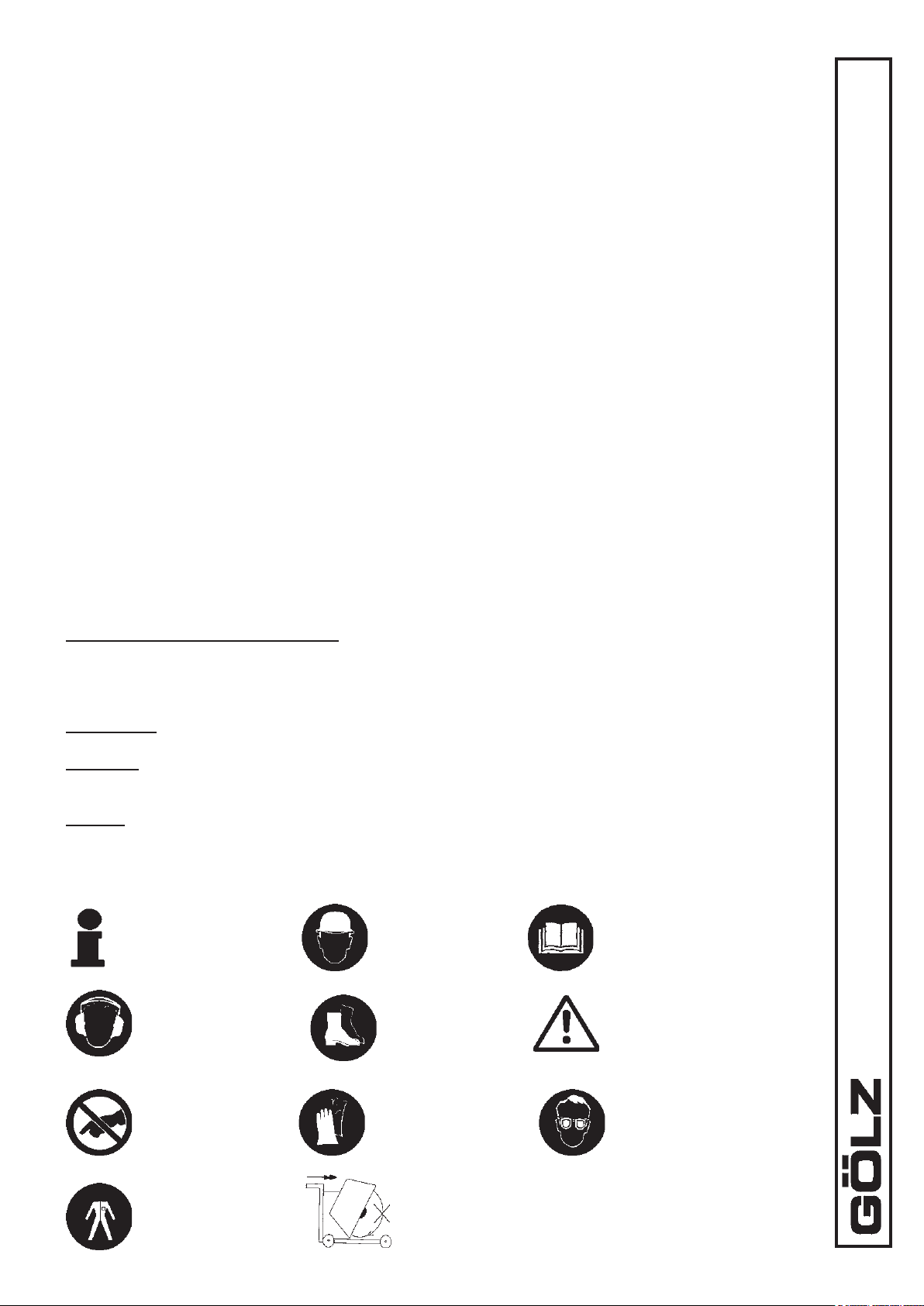
The following signs are used on the machine and in the manual:
Important
information!
Wear ear
protection!
Wear safety
helmet!
Wear safety
boots!
Read owner’s manual
before the rst initiation!
General danger warning!
Do not touch!
Wear safety
clothing!
Wear safety
gloves!
During cuts displace the oor saw only with non
rotating blade (not running engine)!
4
Wear safety glasses!
Page 5

2.2 Basic operation and designated use of the machine
n The machine has been built in accordance with state-of-the-art standards and the recognized safety
rules. Nevertheless, its use may constitute a risk to life and limb of the user or of third parties, or cause
damage to the machine and to other material property.
n The machine must only be used in technically perfect condition in accordance with its designated use
and the instructions set out in the operating manual, and only by safety-conscious persons who are fully
aware of the risks involved in operating the machine. Any functional disorders, especially those affecting
the safety of the machine, should therefore be rectied immediately.
n Separation building implements are exclusively designed for sawing, slotting, drilling a.s.o. of abrasive
building material at building sites using tools in accordance with the manufacturer’s instruction.
n They are exclusively designed for cutting rm built-in building material.
n Using the machine for purposes other than those mentioned above (such as for) is considered contrary
to its designated use. The manufacturer cannot be held liable for any damage resulting from such use.
The risk of such misuse lies entirely with the user. Operating the machine within the limits of its designated use also involves observing the instructions set out in the operating manual and complying with
the inspection and maintenance directives.
2.3 Organizational measures
n The operating instructions must always be at hand at the place of use of the machine, e.g. by stowing
them in the tool compartment or tool-box provided for such purpose.
n In addition to the operating instructions, observe and instruct the user in all other generally applicable
legal and other mandatory regulations relevant to accident prevention and environmental protection.
These compulsory regulations may also deal with the handling of hazardous substances, issuing and/or
wearing of personal protective equipment, or trafc regulations.
n The operating instructions must be supplemented by instructions covering the duties involved in super-
vising and notifying special organizational features, such as job organization, working sequences or the
personnel entrusted with the work.
n Personnel entrusted with work on the machine must have read the operating instructions and in particular
the chapter on safety before beginning work. Reading the instructions after work has begun is too late.
This applies especially to persons working only occasionally on the machine, e.g. during setting up or
maintenance.
n Check - at least from time to time - whether the personnel is carrying out the work in compliance with the
operating instructions and paying attention to risks and safety factors.
n For reasons of security, long hair must be tied back or otherwise secured, garments must be close-tting
and no jewellery - such as rings - may be worn. Injury may result from being caught up in the machinery
or from rings catching on moving parts.
n Use protective equipment wherever required by the circumstances or by law.
n Observe all safety instructions and warnings attached to the machine.
n See to it that safety instructions and warnings attached to the machine are always complete and perfectly
legible.
n In the event of safety-relevant modications or changes in the behaviour of the machine during operation,
stop the machine immediately and report the malfunction to the competent authority/person.
n Never make any modications, additions or conversions which might affect safety without the supplier’s
approval. This also applies to the installation and adjustment of safety devices and valves as well as to
welding work on load-bearing elements.
n Spare parts must comply with the technical requirements specied by the manufacturer. Spare parts from
original equipment manufacturers can be relied to do so.
5
Page 6

7
n Replace hydraulic hoses within stipulated and appropriate intervals even if no safety-relevant defects
have been detected.
n Adhere to prescribed intervals or those specied in the operating instructions for routine checks and
inspections!
n For the execution of maintenance work, tools and workshop equipment adapted to the task on hand are
absolutely indispensable.
n The personnel must be familiar with the location and operation of re extinguishers.
n Observe all re-warning and re-ghting procedures.
2.4 Selection and qualication of personnel
n Any work on and with the machine must be executed by reliable personnel only. Statutory minimum age
limits must be observed.
n Employ only trained or instructed staff and set out clearly the individual responsibilities of the personnel
for operation, set-up, maintenance and repair.
n Make sure that only authorized personnel works on or with the machine.
n Dene the machine operator’s responsibilities - also with regard to observing trafc regulations - giving
the operator the authority to refuse instructions by third parties that are contrary to safety.
n Do not allow persons to be trained or instructed or persons taking part in a general training course to
work on or with the machine without being permanently supervised by an experienced person.
n Work on the electrical system and equipment of the machine must be carried out only by a skilled electri-
cian or by instructed persons under the supervision and guidance of a skilled electrician and in accordance with electrical engineering rules and regulations.
n Work on the hydraulic system must be carried out only by personnel with special knowledge and experi-
ence of hydraulic equipment.
2.5 Safety instructions governing specic operational phases
FS 250 B
Standard operation
n Avoid any operational mode that might be prejudicial to safety.
n Take the necessary precautions to ensure that the machine is used only when in a safe and reliable
state. Operate the machine only if all protective and safety-oriented devices, such as removable safety
devices, emergency shut-off equipment, sound-proong elements and exhausters, are in place and
fully functional. Before beginning work, familiarize yourself with the surroundings and circumstances of
the site, such as obstacles in the working and travelling area, the soil bearing capacity and any barriers
separating the construction site from public roads.
n Check the machine at least once per working shift for obvious damage and defects. Report any changes
(incl. changes in the machine’s working behaviour) to the competent organization/person immediately.
If necessary, stop the machine immediately and lock it.
n In the event of malfunctions, stop the machine immediately and lock it. Have any defects rectied im-
mediately.
n During start-up and shut-down procedures always watch the indicators in accordance with the operating
instructions.
n Before starting up or setting the machine in motion, make sure that nobody is at risk.
Special work in conjunction with utilization of the machine and maintenance and repairs during operation; disposal of parts and consumables
n Observe the adjusting, maintenance and inspection activities and intervals set out in the operating in-
structions, including information on the replacement of parts and equipment. These activities may be
executed by skilled personnel only.
6
Page 7

n Brief operating personnel before beginning special operations and maintenance work, and appoint a
person to supervise the activities.
n In any work concerning the operation, conversion or adjustment of the machine and its safety-oriented
devices or any work related to maintenance, inspection and repair, always observe the start-up and shutdown procedures set out in the operating instructions and the information on maintenance work.
n Ensure that the maintenance area is adequately secured.
n If the machine is completely shut down for maintenance and repair work, it must be secured against
inadvertent starting by:
- locking the principal control elements and removing the ignition key and/or
- attaching a warning sign to the main switch.
n To avoid the risk of accidents, individual parts and large assemblies being moved for replacement pur-
poses should be carefully attached to lifting tackle and secured. Use only suitable and technically perfect
lifting gear and suspension systems with adequate lifting capacity. Never work or stand under suspended
loads.
n The fastening of loads and the instructing of crane operators should be entrusted to experienced persons
only. The marshaller giving the instructions must be within sight or sound of the operator.
n Clean the machine, especially connections and threaded unions, of any traces of oil, fuel or preservatives
before carrying out maintenance/repair. Never use aggressive detergents. Use lint-free cleaning rags.
n Before cleaning the machine with water, steam jet (high-pressure cleaning) or detergents, cover or tape
up all openings which - for safety and functional reasons - must be protected against water, steam or
detergent penetration. Special care must be taken with electric motors and switchgear cabinets.
n After cleaning, remove all covers and tapes applied for that purpose.
n After cleaning, examine all fuel, lubricant, and hydraulic uid lines for leaks, loose connections, chafe
marks and damage. Any defects found must be rectied without delay.
n Always tighten any screwed connections that have been loosened during maintenance and repair.
n Any safety devices removed for set-up, maintenance or repair purposes must be retted and checked
immediately upon completion of the maintenance and repair work.
n Ensure that all consumables and replaced parts are disposed of safely and with minimum environmental
impact.
2.6 Warning of special dangers
Electric energy
n Use only original fuses with the specied current rating. Switch off the machine immediately if trouble
occurs in the electrical system.
n Work on the electrical system or equipment may only be carried out by a skilled electrician himself or by
specially instructed personnel under the control and supervision of such electrician and in accordance
with the applicable electrical engineering rules.
n The electrical equipment of machines is to be inspected and checked at regular intervals. Defects such
as loose connections or scorched cables must be rectied immediately.
n Necessary work on live parts and elements must be carried out only in the presence of a second person
who can cut off the power supply in case of danger by actuating the emergency shut-off or main power
switch. Secure the working area with a red-and-white safety chain and a warning sign. Use insulated
tools only.
7
Page 8

9
Gas, dust, steam, smoke
n Carry out welding, ame-cutting and grinding work on the machine only if this has been expressly author-
ized, as there may be a risk of explosion and re.
n Before carrying out welding, ame-cutting and grinding operations, clean the machine and its surroundings
from dust and other inammable substances and make sure that the premises are adequately ventilated
(risk of explosion).
n Operate internal combustion engines and fueloperated heating systems only on adequately ventilated
premises. Before starting the machine on enclosed premises, make sure that there is sufcient ventilation. Observe the regulations in force at the respective site.
Hydraulic and pneumatic equipment
n Work on hydraulic equipment may be carried out only by persons having special knowledge and experi-
ence in hydraulic systems.
n Check all lines, hoses and screwed connections regularly for leaks and obvious damage. Repair damage
immediately. Splashed oil may cause injury and re.
n Depressurize all system sections and pressure pipes (hydraulic system, compressed-air system) to be
removed in accordance with the specic instructions for the unit concerned before carrying out any repair
work.
n Hydraulic and compressed-air lines must be laid and tted properly. Ensure that no connections are in-
terchanged. The ttings, lengths and quality of the hoses must comply with the technical requirements.
Noise
n During operation, all sound bafes must be closed.
n Always wear the prescribed ear protectors.
Oil, grease and other chemical substances
FS 250 B
n When handling oil, grease and other chemical substances, observe the product-related safety regula-
tions.
n Be careful when handling hot consumables (risk of burning or scalding).
2.7 Machinery and equipment used at frequently changing places of
operation)
n For loading only use lifting gear and tackle of sufcient capacity.
n Appoint a competent marshaller to assist in the lifting operations.
n Lift machinery and equipment properly with suitable lifting gear and only in accordance with the operating
instructions (xing points for lifting tackle, etc . . .).
n Only use suitable means of transport of adequate carrying capacity.
n Fasten the loads safely using the suitable xing points.
n Before or immediately after completion of the loading operations the machine must be secured by means
of recommended/supplied devices against unintentional changes of position and a corresponding warning sign attached to the machine. Before recommissioning the machine these devices must be properly
removed.
n Carefully ret and fasten all parts to be removed for transport purposes before recommissioning the
machine.
n For recommissioning only proceed in accordance with the operating instructions.
8
Page 9
3. Description
3.1 Intended use-description
n Operate the oor saw only using tools in accordance with the manufacturer’s instruction. Using other
tools is considered contrary to its designated use. The manufacturer cannot be held liable for any damage resulting from such use. The risk of such misuse lies entirely with the user.
n Operate petrol driven oor saws only with motor fuel the engine manufacturer species.
Information: Unconditional observe the owner’s manual of the engine manufacturer, which is added!
9
15
10
1
2
11
12
3
8
14
13
7
6
5
15
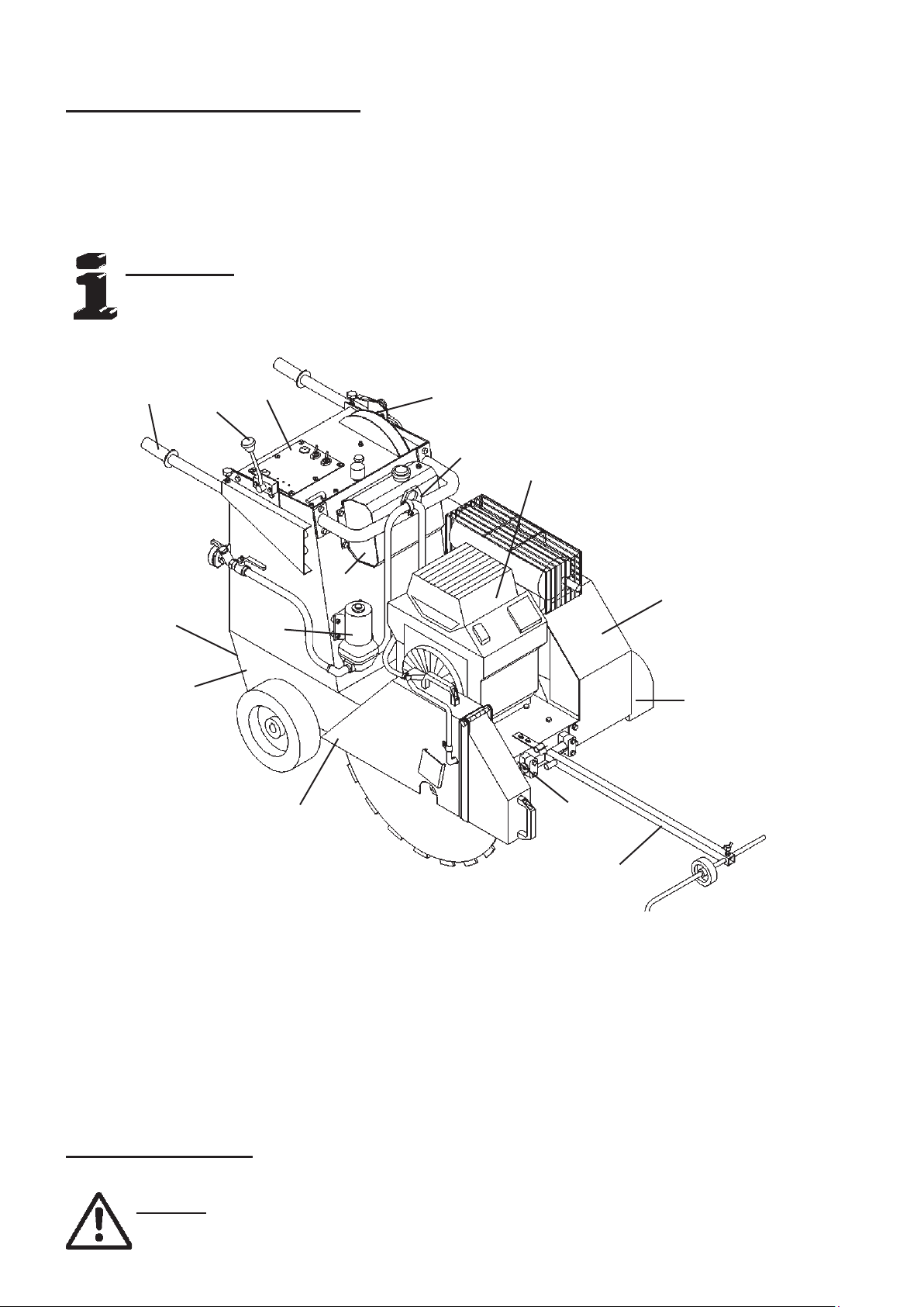
1. Frame
2. Undercarriage
3. Blade guard
4. Pointer unit
5. Flange guard
6. V-belt guard
7. Engine
8. Fuel tank
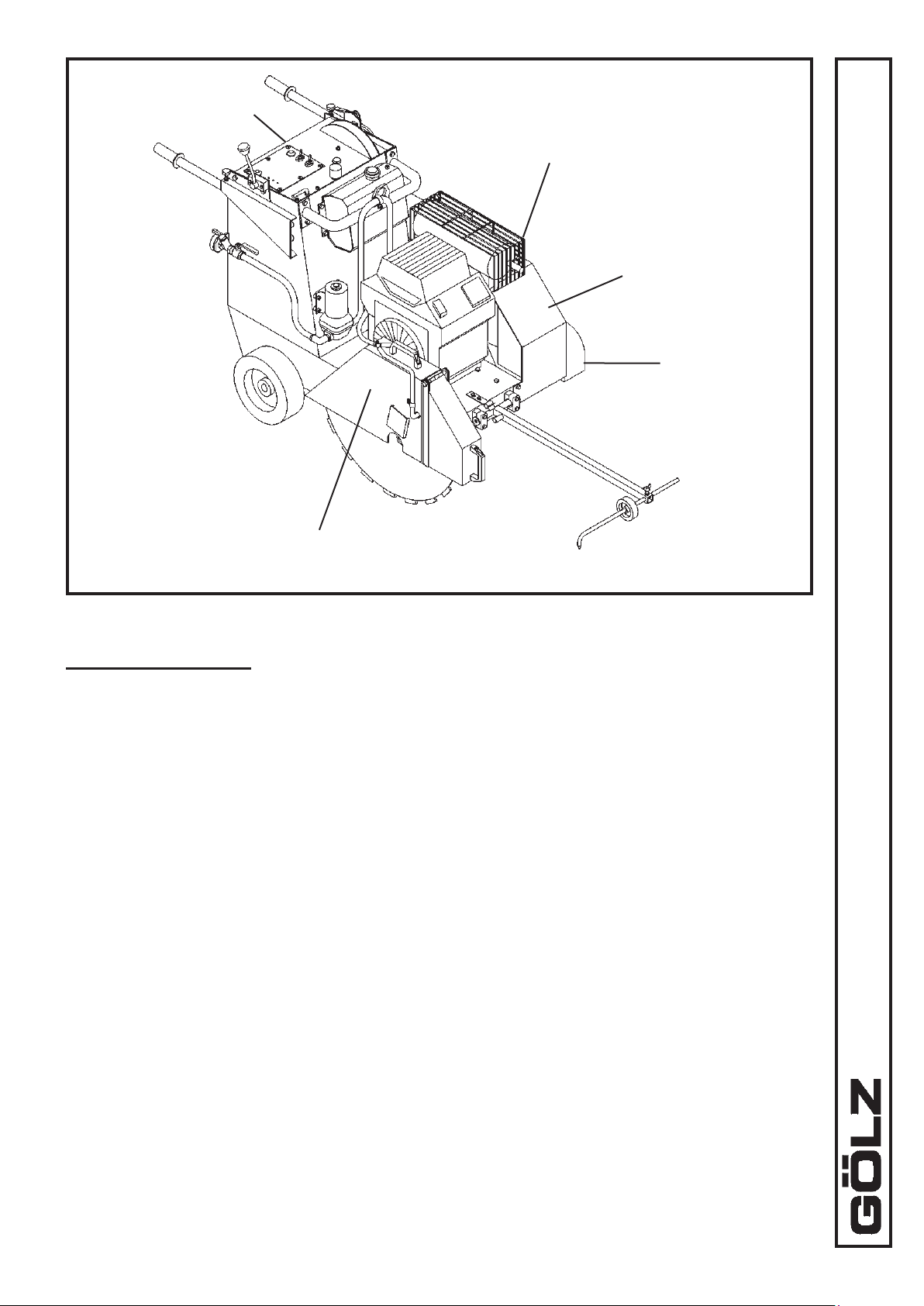
3.3 Safety devices
Danger: During cutting or displacing the oor saw, all safety devices shown
below must be mounted!
4
9. Adjustable handle bars
10. Feed-control lever
11. Dashboard
12. Electrical water pump
13. Lifting eye
14. Depth control
15. Fixing points
9
Page 10
11
Maintenance ap
(rear side)
Blade guard for max. blade size
of 800 mm - 31.5 in.
Mufer
guard
V-belt guard
FS 250 B
Flange
guard
3.4 Technical data
Max. cutting depth: 280 mm - 8.65 in.
Max. blade-Ø: 800 mm - 31.5 in.
Blade shaft size: Ø 25.4 mm - 1 in.
Flange size: Ø 145 mm - 5.7 in.
Engine: KOHLER-petrol engine, 2-cylinder, 3600 rpm,
4-cycle, 18.5 kW (25 HP), air-cooled with
electric start
Blade shaft speed: 1600 rpm
Max. cutting speed with
blade size Ø 800 mm - 31.5 in.: 62,8 m/s - 175 ft./sec.
Feed: Electro-hydraulically traversing gear
Lifting: Electro-hydraulically quick-lifting
Water supply: Electrical water pump
V-belt tension: Automatically V-belt tensioner
Dimensions (L x W x H): approx. 1340 x 800 x 1040 mm
52.75 x 31.5 x 40.95 in.
10
Page 11
Weight empty: approx. 280 kg - 616 lbs.
Kerb weight: approx. 292 kg - 643 lbs. (filled fuel tank and
mounted blade Ø 750 mm - 23.6 in.)
Sound power level: 106 dB(A)
Sound pressure level: 90 dB(A)
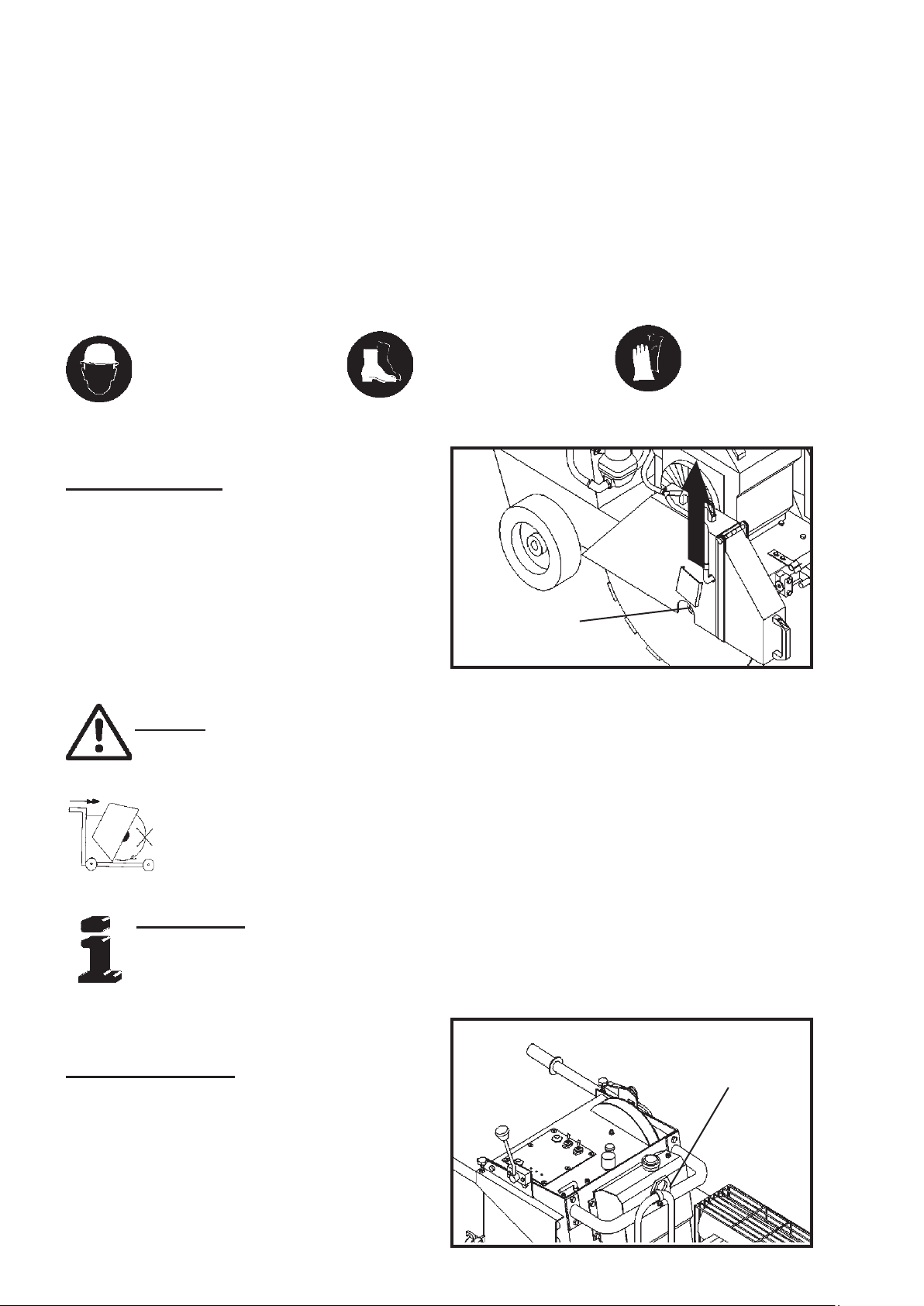
4. Transport
Injury hazard: Down
coming parts!
4.1 Preparation
Remove the toggle of the main switch in the control
panel before transporting. Dismount the blade and attach again the blade guard.
Immediately after completion of the loading operations
the machine must be secured with lashing straps or
similarat at the xing points (2x at the back of the
machine,1x at the front).
Danger: Only use the lifting eye for lifting the oor saw!
Injury hazard: Down
coming parts!
SW 36
Injury hazard:
Sharp edges!
During cuts displace the oor saw only with non rotating blade (not running engine)! Use the electro-hydraulically traversing gear which can be
actuated by turning the toggle of the main switch!
Information: The max. time of using the electro-hydraulically traversing gear
should not exceed 30 minutes. Otherwise it may result in discharge of the battery and the battery can be damaged!
4.2 Transporting
Check that all parts of the oor saw are well fastened
before transporting. For loading only use lifting gear
and tackle of sufcient capacity (kerb weight of the
oor saw approx. 292 kg - 643 lbs.). Lift the oor saw
using the lifting eye.
Lifting eye
11
Page 12
13
5. Installation and operation
5.1 Installation
n Place the oor saw on an even, rm and stable ground. Have the working area well lightened. Keep the
working area clean, cluttered areas invite injuries. Operating the oor saw on enclosed premises, make
sure that there is sufcient ventilation. Observe the regulations in force at the respective site.
n Observe the manufacturer’s information for connecting power and water supply.
n Lay all hydraulic lines or cables that damages will be prevented.
n Blade mounting
- Mount the blade to the manufacturer’s odds (Observe the min. ange-Ø; use only original
screws or nuts).
- Use only blade diameters which are allowed by the manufacturer.
5.2 Initiation and operation
Information: Unconditional observe the owner’s manual of the engine manufacturer!
Danger: Never touch rotating parts like blade shaft or blade while operating!
Danger: Rotating parts may pull in clothing! Wear tightly clothing!
FS 250 B
3
Danger: Down coming parts can cause injuries to the operator!
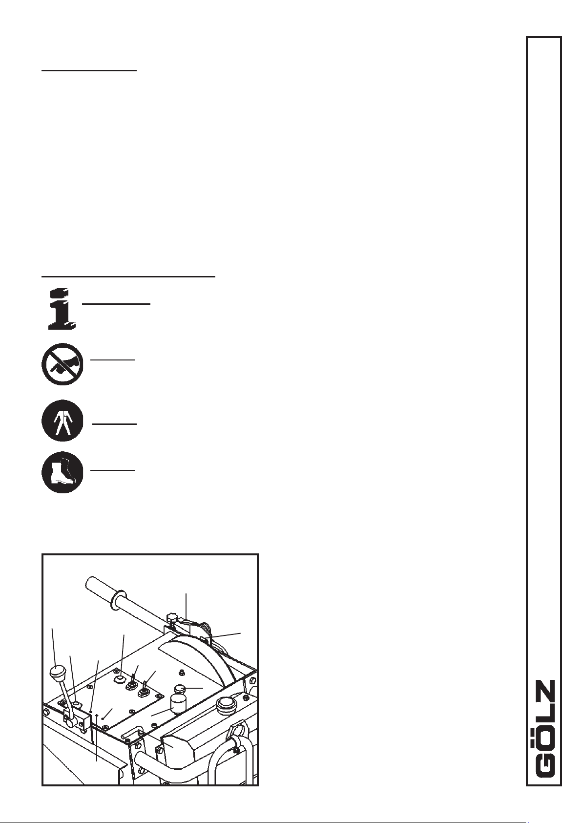
Operating elements
8
Control panel
1
13
9
11
2
12
4
10
7
6
1. Lifting
2. Lowering
3. Foreward - Reverse
4. RPM
5
5. Depth control
6. Main switch toggle
7. Choke
8. Engine starter
9. Traversing gear ON-OFF
10. Water pump ON-OFF
11. Charge indicator lamp
12. Oil-pressure indicator lamp
13. (without function)
12
Page 13

n Remove the toggle of the main switch in the control panel or disconnect the power supply before mount-
ing or changing blade.
Information: Clean all fastening devices of the blade (anges, thread of the
blade shaft, screws and nuts) before mounting the blade!
n The working area is reserved only for the operator. Keep unauthorized persons out of the working
area.
n Make sure the operator always has well sight to the working area. He always has to intervene in the
working process.
n Never operate the oor saw without mounted safety devices.
n In the cutting speed range all used blades must be designed for the max. rpm of the oor saw.
n Never use faulty or damaged blades.
Danger: Faulty or damaged blades can cause injuries to the operator and other
persons!
n Check the correct rotation of the blade to the spindle shaft.
Information: Wrong rotation of the blade will result in more wear of the
blade!
Danger: Wrong rotation of the blade may result in segments cracking off and
can cause injuries to the operator or other persons!
n Check the blade is well fastened before beginning to operate.
n Use only blades suitable to the blade acceptance (arbor hole, anges).
n Use only blade suitable to the material to be cut.
n Check the correct water ow to the blade.
n If harmful or explosive stuffs like dust, milk-of-lime arise while cutting, observe local regulations.
Danger: Demolitioning parts can cause injuries to the operator while cutting!
n When travelling on public roads, ways and places always observe the valid trafc regulations and, if nec-
essary, make sure beforehand that the oor saw is in a condition compatible with these regulations.
n After operating secure the oor saw against unintentional moving.
Danger: The sound pressure may exceed 85 dB(A)!
n Appropriate to the application of the oor saw it could be necessary to wear further protective equip-
ment.
13
Page 14

15
Danger:
operator!
Mounting the blade
Remove the toggle of the main switch in the control panel
before mounting the blade. Mount a blade with arbor
hole of 25.4 mm - 1 in. and a max. blade size of Ø 600
mm - 23.6 in. Check the correct rotation - arrows on the
blade and blade guard. Attach the blade guard.
Down coming parts at the building site can cause injuries to the
Water supply
FS 250 B
SW 36
1
Dashboard
ON
2
3
OFF
3. Water pump ON-OFF
Attention:
will appear!
Using a GEKA-coupler connect the water supply to the oor saw coupler (1). Check the ball valve (2) is closed
(ball valve lever in 90°-position to the water ow) and the switch for the water pump (3) is in OFF-position.
Water supply from waterworks: Open the ball valve (2) (ball valve lever in the water ow position)
Switch the water pump (3) in OFF-position
Water supply from water reservoir: Open the ball valve (2) (ball valve lever in the water ow position)
Switch the water pump (3) in ON-position
Avoid dry-running of the water pump! Drain the water pump if frost
14
Page 15

Control panel
Cutting operation
9
3
8
ON
Control panel
1
13
11
2
10
OFF
4
6
7
5
9. Traversing gear ON-OFF
1. Lifting
2. Lowering
3. Foreward - Reverse
4. RPM
5. Depth control
6. Main switch toggle
7. Choke
8. Engine starter
10. Water pump ON-OFF
11. Charge indicator lamp
12. Oil-pressure indicator lamp
13. (without function)
12
Danger: Operating with too high feed the oor saw might rise out of cut! In
emergency situations shut down the oor saw immediately by turning the
toggle (6) of the main switch!
Warning: Before switching on the traversing gear the lever (3) must be denitely in 0-position , otherwise the machine starts directly. The 0-position
does not shut down the traversing gear!
Completely rise the oor saw (blade may have no ground contact). Cut in the main switch using the toggle (6).
If the engine is cold, pull the CHOKE (7). Start the engine with the starter (8) and with low rpm let the engine
warm up. Pull down the CHOKE and slowly increase the rpm using the lever (4). How described connect the
water supply and slowly lower the oor saw turning the valve (2). Push the depth control to the correct 0-position of the balde Ø and slowly lower the oor saw to the required cutting depth. Switch ON the traversing
gear with the switch (9) and select the correct feed with the feed control lever (3). After cutting push the feed
control lever (3) in 0-position and completely lift the oor saw with the press-bottom switch (1). Switch OFF the
traversing gear with the switch (9) and close the water supply (rst switch OFF the water pump and then close
the ball valve). Shut down the engine with the toggle (6) of the main switch and secure the oor saw against
unauthorized starting by pulling off the toggle (6). Maximum longitudinal- and cross-position of the machine in
parking position ≤ 10°.
15
Page 16

17
6. Maintenance
6.1 General
Information: Unconditional observe the owner’s manual of the engine manufacturer, which is added!
Information: Clean the oor saw after every operation. Observe local environmental regulations!
Attention: Drain the water pump if frost will appear!
Attention: Work on hydraulic equipment may be carried out only by persons
having special knowledge and experience in hydraulic systems!
FS 250 B
Attention: When handling oil, grease and other chemical substances, observe
the product-related safety regulations!
n For maintenance jobs the oor saw has to be shut down.
n For maintenance jobs which must be done while the oor saw is running, the blade has to be dismounted
before beginning the job.
6.2 V-belts
The blade shaft V-belts are maintenance-free. In the case of repair call in a second person. Dismount the anges
and the V-belt guard. Using one of the handle bars pull up the V-belt tensioner and replace the V-belts. Mount
again the V-belt guard and the anges.
16
Page 17

Danger: Unintentional striking back of the V-belt tensioner can cause in
pinching injuries to the operator!
6.3 Lubrication chart
1
2
1. Hydraulic power unit: Oil change after 1000 working
hours or once a year0,9 Litre 55 cu. in. ATF
2. Static displacement drive: Oil change after 500 working
hours or once a year 0,65 Litre 40 cu. in. HLP46
3
4
3. Driving axle: Oil change after 500 working
hours or once a year1,3 Litre 79 cu. in. SAE90
4. Battery: Check uid level once a month
and rell with distilled water if
neccessary
17
Page 18

19
7
5
FS 250 B
6
8
5. Spindle shaft bearings: After 20 working hours grease
with heat resistance fat
6. Undercarriage bearings: After 20 working hours grease
with heat resistance fat
7. Hydraulic cylinder bolts: Clean from time to time and
grease with some drops of oil
8. Front axle: Clean from time to time and
grease with some drops of oil
18
Page 19

7. Troubleshooting
Attention: In the event of changes in the behaviour of the oor saw during
operation, stop the machine immediately and report the malfunction to the
competent authority/person!
PROBLEM CAUSE REMEDY
Engine
Fuel tank empty Rell
Engine does not run!
Fuel lines obstructed Clean fuel lines
For further troubleshooting refer to the owner’s manual of the engine manufacturer,
which is added!
Lifting device
Faulty lifting cylinder Replace
Floor saw lowers with Leaking lifting cylinder Replace seals if necessary
closed ow control valve!
Hydraulic system leaking Tighten connections
Floor saw does not fully Lifting cylinder or under- Replace lifting cylinder or
lower! carriage tight straighten undercarriage
Depth stop screw not Adjust
correctly adjusted
Oil level in the hydraulic Rell
Floor saw does not fully power unit too low
lift!
Air in hydraulic system Ventilate
Feed
Faulty toothed belt Replace
No feed! Malfunction of electrical Have electrical installation
installation checked
(Fuses inside the
dashboard)
Jerky feed! Oil level in the static Rell
displacement drive too low
Oily rubber bandages Clean
Slippy driving wheel! Only one driving wheel Check undercarriage on
in ground contact even surface, straighten if it
is warped
19
Page 20

21
Wearing parts for contruction devices mentioned in the operating manual
such as drilling and sawing machines
Wearing parts are the parts subject to operation-related (natural) wear during proper use of the
device. The wearing time cannot be uniformly dened, and differs according to the intensity
of use. The wearing parts must be adjusted, maintained and, if necessary, replaced for the
specic device in accordance with the manufacturer’s operating manual. Operation-related
wear is not a reason for defect claims.
• Feed and drive elements such as toothed racks, gearwheels, pinions, spindles,
spindle nuts, spindle bearings, cables, chains, sprockets, belts
• Seals, cables, hoses, packings, connectors, couplings and switches for pneu
matic, hydraulic, water, electrical and fuel systems
• Guide elements such as guide strips, guide bushes, guide rails, rollers, bea-
rings, sliding protection supports
• Clamping elements for quick-separating systems
• Flushing head seals
• Slide and roller bearings that do not run in an oil bath
• Shaft oil seals and sealing elements
• Friction and safety clutches, braking devices
• Carbon brushes, commutators/armatures
• Easy-release rings
• Control potentiometers and manual swiching elements
• Securing elements such as plugs, anchors, screws and bolts
• Fuses and lamps
• Auxiliary and operating materials
• Bowden cables
• Discs
• Diaphragms
• Spark plugs, glow plugs
• Parts of the reversing starter such as the starting rope, starting pawl, starting
roller and starting spring
• Sealing brushes, rubber seals, splash protection cloths
• Filters of all kinds
• Drive rollers, deection rollers and bandages
• Cable anti-twist elements
• Running and drive wheels
• Water pumps
• Cut-material transport rollers
• Drilling, parting and cutting tools
• Energy storage
FS 250 B
Wearing parts of this machine are marked in the spare parts list page 21 with (Ò) and the
spare parts with (#).
20
Page 21

8. Spare parts list
Always indicate:
- machine/model/serial number
- item number and description of the spare part
- amount of spare parts desired
- full address
- goods to be sent by regular mail, express, etc.
Zeichenerklärung
¡ = bestehend aus Pos.
l = darin enthalten Pos.
u = ohne Abbildung
n = auf Anfrage
Ò = Verschleißteil
# = Ersatzteil
â = ab Masch.-Nr.
á = bis Masch.-Nr.
Key to symbols
¡ = consisting of pos.
l = including pos.
u = not illustrated
n = special order
Ò = Wearing part
# = Spare part
â = from machine number
á = up to machine number
21
Légende
¡ = se composant des pos.
l = y compris pos.
u = non illustré
n = commande spécial
Ò = Pièce d’usure
# = Pièce de rechange
â = a partir de machine Nº
á = jusqu'a machine Nº
Page 22

FS 250 B
23
Ersatzteile für Maschinen neuerer Bauart - Spare parts for sequential models - Pièces de rechange pour machines de dernier construction
22
Page 23

Pos. Nr. Type Qty. Benennung - Part name - Désignation
1 0282 250 0690 # 2 Klemmfeder - Clamping device - dispositif de serrage
2 0282 250 0657 # 1 Schutzhaube Keilriemen - V-belt guard - Capot de protection
pour courroie
3 0282 250 0759 # 1 Schutzhaube Flansch - Flange guard - Capot de protection pour
asque de xation
4 0282 250 0768 # 1 Versteifung Bodenblech - Stiffening plate - Tôle de plaque
5 0285 300 0068 # 2 Schraube - Screw - Vis - M6x 20 DIN 933
6 0298 900 0006 # 2 Scheibe - Washer - Rondelle - A6,4 DIN 9021
7 0282 250 0005 # 1 Schraube - Screw - Vis - M8x16 DIN 933
8 0282 250 0032 # 2 Passfeder - Key - Clavette - 8,0x7x22 DIN 6885
9 0282 250 0531 # 2 S-Flansch aussen - Outer ange - Flasque de xation - D140
10 0282 250 0530 # 2 S-Flansch innen - Inner ange - Flasque de xation - D140
11 0282 250 0164 # 2 Kegelstift - Taper pin - Goupille conique - 8x30 DIN 1
12 0282 250 0175 # 1 Mutter - Nut - Ecrou - M24x1,5 L DIN 934
13 0282 250 0031 # 1 Mutter - Nut - Ecrou - M24x1,5 DIN 934
14 0282 250 0547 Ò 2 Stehlager - Pedestal bearing - Chaise palier - UCPW 208-D40
15 0282 200 0604 # 1 Schneidwelle - Spindle shaft - Arbre
16 0282 300 0171 # 1 Passfeder - Key - Clavette - 12,0x8x70 DIN 6885
17 0282 250 0571 # 1 Keilriemenscheibe - V-belt pulley - Poulie à gorge pour courroie
trapézoidale - DW150x6SPZ TL-D40
0282 250 0872 # 1 Keilriemenscheibe - V-belt pulley - Poulie à gorge pour courroie
trapézoidale - DW180x6SPZ TL2517 â 0251057
u 0282 250 0047 # 1 TL-Buchse - TL-Bushing - TL-douille - D40-2517 â 0251057
18 0282 250 0758 # 1 Aufnahme Richtungsanzeiger - Pointer unit acceptance Logement d’indicatuer de direction
19 0282 250 0765 # 1 Anzeiger - Pointer - Indicateur
20 0282 250 0777 # 1 Rad - Roller - Poulie - D125
21 0295 000 0167 # 2 Sicherungsring - Circlip - Circlip - 12x1,0 DIN 471
22 0282 150 0034 # 2 Flügelschraube - Wing screw - Vis à oreilles - M8x20 DIN 316
23 0282 250 0649 # 2 Befestigungsschelle - Pipe clamp - Collier de xation - D20
24 0282 250 0768 # 1 Versteifung Bodenblech - Stiffening plate - Tôle de renfort
25 0286 570 0052 # 4 Mutter - Nut - Ecrou - M10 DIN 982
26 0286 570 0047 # 4 Scheibe - Washer - Rondelle - B10,5 DIN 125
27 0282 300 0040 # 1 Schraube - Screw - Vis - M16x90 DIN 933
28 0281 045 0051 # 1 Mutter - Nut - Ecrou - M16 DIN 934
Ersatzteile für Maschinen neuerer Bauart - Spare parts for sequential models - Pièces de rechange pour machines de dernier construction
Pos. Nr. Type Qty. Benennung - Part name - Désignation
1 0282 250 0824 # 1 Bodenblech - Floor panel - Panneau
2 0282 250 0821 # 1 Schneidwelle - Spindle shaft - Arbre
3 0282 250 0823 # 1 Verlängerung Bodenblech - Lengthening oor panel - Rallonge
de Panneau
4 0282 250 0073 # 2 Schraube - Screw - Vis - M8x25 DIN 933
5 0282 250 0006 # 4 Scheibe - Washer - Rondelle - B 8,4 DIN 125
6 0282 065 0005 # 2 Mutter - Nut - Ecrou - M8 DIN 982
7 0282 250 0074 # 2 Mutter - Nut - Ecrou - M14 DIN 982
8 0282 250 0826 # 2 Gewindestift - Set screw - Sans tête - M14x60 DIN 913
9 0295 600 1043 # 2 Scheibe - Washer - Rondelle - B15 DIN 125
23
Page 24

FS 250 B
25
Ersatzteile für Maschinen neuerer Bauart - Spare parts for sequential models - Pièces de rechange pour machines de dernier construction
24
Page 25

Pos. Nr. Type Qty. Benennung - Part name - Désignation
-- 0282 250 0790 # 1 Schutzhaube kpl. - Blade guard assy. - Capot de protection
complet - ¡ Pos. 29 -46
29 0282 250 0757 # 1 Schutzhaube hinten - Blade guard - Capot de protection
0282 250 0798 # 1 Schutzhaube hinten - Blade guard - Capot de protection â 0251057
30 0282 250 0778 # 1 Schutzhaube vorne - Blade guard - Capot de protection
0282 250 0799 # 1 Schutzhaube vorne - Blade guard - Capot de protection â 0251057
31 0282 250 0775 # 2 Griff - Bow-type handle - Poignée en forme d’derier
32 0282 250 0553 1 Spritzschutz - Splash guard - Protection contre le réfrigérant
33 0282 250 0776 # 2 Schelle - Hose clamp - Bride - D19
34 0282 650 0151 # 1 Y-Stück - Connection - Raccord - D13
35 0298 100 0106 # 1m Schlauch - Hose - Tuyau exible - 13,2x3,3
36 0282 250 0660 # 5 Scheibe - Washer - Rondelle - A6,4 DIN 125
37 0267 112 5047 # 7 Schraube - Screw - Vis - M6x20 DIN 912
38 0267 113 0095 # 1 Normaschelle - Hose clamp - Bride - D20-22
39 0282 120 0061 # 1 Schraube - Screw - Vis - M10x120 DIN 933
40 0282 250 0073 # 4 Schraube - Screw - Vis - M8x25 DIN 933
41 0282 250 0006 # 4 Scheibe - Washer - Rondelle - B8,4 DIN 125
42 0298 900 0008 # 6 Scheibe - Washer - Rondelle - A8,4 DIN 9021
43 0282 065 0005 # 4 Mutter - Nut - Ecrou - M8 DIN 982
44 0281 045 0027 # 9 Mutter - Nut - Ecrou - M6 DIN 982
45 0285 000 0015 # 1 Mutter - Nut - Ecrou - M12 DIN 982
46 0282 250 0663 # 2 Scheibe - Washer - Rondelle - A13 DIN 125
47 0295 000 3509 # 6 Schraube - Screw - Vis - M10x20 DIN 7380
48 0282 250 0662 # 6 Scheibe - Washer - Rondelle - A10,5 DIN 125
49 0282 250 0767 # 1 Abschlussblech - Cover plate - Couvercle de fermenture
50 0282 250 0753 # 1 Bodenblech - Floor panel - Panneau
51 0282 250 0075 # 4 Gewindestift - Set screw - Sans tête - M14x50 DIN 913
52 0295 600 1043 # 4 Scheibe - Washer - Rondelle - B15 DIN 125
53 0282 250 0641 # 1 Verschlussblech - Guard plate - Tôle de protection
54 0282 150 0035 # 2 Schraube - Screw - Vis - M8x20 DIN 933
55 0285 300 0142 # 4 Mutter - Nut - Ecrou - M6 DIN 934
56 0282 250 0804 # 4 Schraube - Screw - Vis - M6x60 DIN 933
57 0298 100 0106 # 1 Schlauch - Hose - Tuyau exible - 13,2x3,3
58 0282 250 0112 # 1 Schelle - Hose clamp - Bride - D16-25
59 0282 250 0074 # 4 Mutter - Nut - Ecrou - M14 DIN 982
Ersatzteile für Maschinen neuerer Bauart - Spare parts for sequential models - Pièces de rechange pour machines de dernier construction
Pos. Nr. Type Qty. Benennung - Part name - Désignation
1 0282 250 0824 # 1 Bodenblech - Floor panel - Panneau
2 0282 250 0821 # 1 Schneidwelle - Spindle shaft - Arbre
3 0282 250 0823 # 1 Verlängerung Bodenblech - Lengthening oor panel - Rallonge
de Panneau
4 0282 250 0073 # 2 Schraube - Screw - Vis - M8x25 DIN 933
5 0282 250 0006 # 4 Scheibe - Washer - Rondelle - B 8,4 DIN 125
6 0282 065 0005 # 2 Mutter - Nut - Ecrou - M8 DIN 982
7 0282 250 0074 # 2 Mutter - Nut - Ecrou - M14 DIN 982
8 0282 250 0826 # 2 Gewindestift - Set screw - Sans tête - M14x60 DIN 913
9 0295 600 1043 # 2 Scheibe - Washer - Rondelle - B15 DIN 125
25
Page 26

FS 250 B
27
Ersatzteile für Maschinen neuerer Bauart - Spare parts for sequential models - Pièces de rechange pour machines de dernier construction
26
Page 27

Pos. Nr. Type Qty. Benennung - Part name - Désignation
1 0282 250 0750 # 1 Bedienpult - Control panel - Panneau
2 0282 200 0500 Ò 1 Wasserpumpe - Water pump - Pompe à eau
3 0295 000 3503 # 4 Schraube - Screw - Vis - M6x30 DIN 7380
4 0282 250 0660 # 8 Scheibe - Washer - Rondelle - A6,4 DIN 125
5 0282 250 0605 # 2 Bogen - Elbow - Raccord courbé - 90º - 1/2“
6 0282 250 0568 # 1 Kraftstofftank - Fuel tank - Réservoir d’essence
7 0282 250 0112 # 2 Schelle - Hose clamp - Bride - D16-25
8 0298 100 0106 # 0,4m Schlauch - Hose - Tuyau exible - 13,2x3,3
9 0282 150 0031 # 1 Schlauchtülle - Nozzle - Embout à olive - 1/2“x13D
10 0282 150 0047 # 1 Kugelhahn - Ball valve - Robinet à boisseau - 1/2“
11 0282 150 0200 # 1 Doppelnippel - Nipple - Nipple - 1/2“
12 0282 250 0550 # 1 Schmutzfänger - Dirt absorber - Collecteur d’impuretés - 1/2“
13 0282 250 0549 # 1 Kupplung - Coupler - Dispositif d’accouplement - GEKA-G1/2“
14 0282 250 0783 # 1 Wasseranschlussaufnahme - Water supply acceptance Prise d’eau logement
15 0281 045 0027 # 8 Mutter - Nut - Ecrou - M6 DIN 982
16 0286 570 0069 # 8 Scheibe - Washer - Rondelle - A6,4 DIN 125
17 0295 000 3501 # 2 Schraube - Screw - Vis - M6x20 DIN 7380
18 0282 450 0116 # 4 Schraube - Screw - Vis - M12x25 DIN 933
19 0298 900 0013 # 4 Scheibe - Washer - Rondelle - A13 DIN 9021
20 0295 000 0216 # 28 Scheibe - Washer - Rondelle - A10,5 DIN 7349
21 0286 570 0047 # 24 Scheibe - Washer - Rondelle - A10,5 DIN 125
22 0295 000 3517 # 4 Schraube - Screw - Vis - M10x60 DIN 7380
23 0282 250 0771 # 1 Halter Griffrohr rechts - Holding device - Logement
24 0295 000 0010 # 2 Kreuzgriffschraube - Star grip screw - Poignée-étoile - M10x55
25 0282 250 0772 # 1 Halter Griffrohr links - Holding device - Logement
26 0286 570 0052 # 12 Mutter - Nut - Ecrou - M10 DIN 982
27 0282 250 0701 # 1 Regulierhebel - Standard lever - Levier régulateur
28 0295 000 3510 # 4 Schraube - Screw - Vis - M10x25 DIN 7380
29 0281 045 0092 # 2 Schraube - Screw - Vis - M6x45 DIN 933
30 0282 250 0556 # 1 Seilzug mit Schraubnippel - Bowden control with nipple Commande avec nipple
31 0313 000 512 # 2 Schraube - Screw - Vis - M5x12 DIN 7991
32 0295 000 0005 # 1 Regulierhebel - Standard lever - Levier régulateur
Ersatzteile für Maschinen neuerer Bauart - Spare parts for sequential models - Pièces de rechange pour machines de dernier construction
Pos. Nr. Type Qty. Benennung - Part name - Désignation
-- 0285 301 0191 # 1 Wasseranschluss kpl. - Supply of water assy. - Prise d'eau
complet - ¡ Pos.1x4, 6-11
1 0282 200 0505 Ò 1 Wasserpumpe - Water pump - Pompe à eau
2 0295 000 0336 # 2 Reduzierung - Reduktion - Réduction - A-I 3/8" - 1/4"
3 0295 000 3016 # 2 Hahnstück - Nipple - Nipple - 1/4"
4 0295 000 3011 # 2 Schlauchkupplung - Water coupler - Dispositif
d'accouplement - GARDENA 1/2"
5 0284 650 0077 # 1 Winkel - Elbow - Raccord en équerre - I-A 3/8"
6 0298 100 0106 # 0,4m Schlauch - Hose - Tuyau exible - 13,2x3,3
7 0282 250 0112 # 1 Schelle - Hose clamp - Bride - D16-25
8 0282 150 0031 # 1 Schlauchtülle - Nozzle - Embout à olive - 1/2“x13D
9 0282 150 0200 # 1 Doppelnippel - Nipple - Nipple - 1/2“
10 0282 150 0047 # 1 Kugelhahn - Ball valve - Robinet à boisseau - 1/2“
11 0282 250 0550 # 1 Schmutzfänger - Dirt absorber - Collecteur d’impuretés 1/2“
12 0282 250 0266 # 1 Redu Verlängerung - Reduktion extension - Prolongement -
3/8
27
Page 28

FS 250 B
29
Ersatzteile für Maschinen neuerer Bauart - Spare parts for sequential models - Pièces de rechange pour machines de dernier construction
28
Page 29

Pos. Nr. Type Qty. Benennung - Part name - Désignation
33 0282 250 0782 # 1 Transportbügel - Lifting bow
34 0285 300 0015 # 4 Mutter - Nut - Ecrou - M12 DIN 982
35 0282 250 0663 # 8 Scheibe - Washer - Rondelle - A13 DIN 125
36 0295 000 3515 # 2 Schraube - Screw - Vis - M12x35 DIN 7380
37 0295 000 0170 # 2 Scheibe - Washer - Rondelle - A5,3 DIN 125
38 0295 000 0315 # 2 Mutter - Nut - Ecrou - M5 DIN 934
39 0282 250 0591 # 1 Hohlschraube - Banjo bolt - Boulon creux à let femelle -
M14x1,5
40 0282 250 0589 # 1 Ringschlauchstück - Nozzle - Embout à olive - NW5 M14
41 0282 250 0584 Ò 2 Dichtring - Conical nipple - Bague d’étanchéité - CU 14x20x1,5
42 0298 100 0212 Ò 1,0 m Kraftstoffschlauch - Fuel pipe line - Conduite de carburant 6x10 mm
43 0282 065 0005 # 5 Mutter - Nut - Ecrou - M8 DIN 982
44 0285 300 0044 # 2 Kunststoffgriff - Handle - Manche d’outil - 852-10.4KSZ
45 0282 250 0006 # 16 Scheibe - Washer - Rondelle - B8,4 DIN 125
46 0295 000 3505 # 3 Schraube - Screw - Vis - M8x20 DIN 7380
47 0282 250 0632 # 1 Tankverschluss - Fuel tank cap - Bouchon réservoir
48 0282 250 0585 # 1 Verschlussschraube - Screw - Vis - M8x1
49 0282 250 0586 Ò 1 Dichtring - Conical nipple - Bague d`étanchéite - CU 8x12x1
50 0282 250 0575 # 1 Lichtmaschine - Dynamo - Dynamo - 65A/14V
51 0282 250 0789 # 1 Eisengewindeöse - Eye bolt - oeillet de suspension
52 0281 045 0025 # 5 Mutter - Nut - Ecrou - M8 DIN 934
53 0298 900 0008 # 3 Scheibe - Washer - Rondelle - A8,4 DIN 9021
54 0282 250 0003 # 1 Schraube - Screw - Vis - M8x50 DIN 931
55 0282 120 0065 # 1 Schraube - Screw - Vis - M8x90 DIN 931
56 0285 300 0068 # 2 Schraube - Screw - Vis - M6x20 DIN 933
57 0282 250 0660 # 2 Scheibe - Washer - Rondelle - A6,4 DIN 125
58 0267 113 0095 # 1 Normaschelle - Hose clamp - Bride - RSGU 1. 20-22
59 0282 250 0073 # 1 Schraube - Screw - Vis - M8x25 DIN 933
60 0282 250 0764 # 1 Halter Lichtmaschine - Acceptance - Logement
61 0282 250 0760 # 2 Griffrohr - Handlebar - Manche - 27x5,0x720
62 0295 000 0196 # 2 Schelle - Hose clamp - Bride - D7-11
63 0298 900 0010 # 4 Scheibe - Washer - Rondelle - A10,5 DIN 9021
64 0295 000 3511 # 6 Schraube - Screw - Vis - M10x30 DIN 7380
65 0295 000 3508 # 1 Schraube - Screw - Vis - M8x35 DIN 7380
u 0298 100 0117 # 0,7m Kantenschutz - Edge protection - Protège-arête
Ersatzteile für Maschinen neuerer Bauart - Spare parts for sequential models - Pièces de rechange pour machines de dernier construction
Pos. Nr. Type Qty. Benennung - Part name - Désignation
-- 0285 301 0191 # 1 Wasseranschluss kpl. - Supply of water assy. - Prise d'eau
complet - ¡ Pos.1x4, 6-11
1 0282 200 0505 Ò 1 Wasserpumpe - Water pump - Pompe à eau
2 0295 000 0336 # 2 Reduzierung - Reduktion - Réduction - A-I 3/8" - 1/4"
3 0295 000 3016 # 2 Hahnstück - Nipple - Nipple - 1/4"
4 0295 000 3011 # 2 Schlauchkupplung - Water coupler - Dispositif
d'accouplement - GARDENA 1/2"
5 0284 650 0077 # 1 Winkel - Elbow - Raccord en équerre - I-A 3/8"
6 0298 100 0106 # 0,4m Schlauch - Hose - Tuyau exible - 13,2x3,3
7 0282 250 0112 # 1 Schelle - Hose clamp - Bride - D16-25
8 0282 150 0031 # 1 Schlauchtülle - Nozzle - Embout à olive - 1/2“x13D
9 0282 150 0200 # 1 Doppelnippel - Nipple - Nipple - 1/2“
10 0282 150 0047 # 1 Kugelhahn - Ball valve - Robinet à boisseau - 1/2“
11 0282 250 0550 # 1 Schmutzfänger - Dirt absorber - Collecteur d’impuretés 1/2“
12 0282 250 0266 # 1 Redu Verlängerung - Reduktion extension - Prolongement -
3/8
29
Page 30

FS 250 B
31
Ersatzteile für Maschinen älterer Bauart - Spare parts for previous models - Pièces de rechange pour machines d´ancienne construction
30
Page 31

Pos. Nr. Type Qty. Benennung - Part name - Désignation
1 0282 450 0513 # 6 Winkel - Elbow - Raccord courbé - XEVW 10LV
2 0291 1041 # 1 T-Stück - T-piece - Pièce en T - XEVT 10LV
3 0282 250 0650 # 2 Drosselrückschlagventil - Flow control valve - Soupape
étranglement
4 0291 1018 # 1 Nippel - Fitting - Nipple - GE 10L-1/8“
5 0291 1010 # 2 Nippel - Fitting - Nipple - XGE 10L-1/4“
6 0282 250 0555 # 1 Drossel - Throttling - Étranglement - XGE 10L-1/4“ D=0,6mm
7 0291 1010 # 1 Nippel - Fitting - Nipple - XGE 10L-1/4“
8 0291 1030 # 1 Nippel - Fitting - Nipple - EVGE 10L-1/4“
9 0291 089 Ò 1 Schlauch - Hose - Tuyau exible - DN08x500
10 0291 099 Ò 2 Schlauch - Hose - Tuyau exible - DN08x750
11 0291 1016 # 1 Nippel - Fitting - Nipple - XGE 10L-3/8“
12 0282 250 0732 # 1 Rückwand - Rear panel - Panneau arrière - l 2xPos.13
13 0282 250 0538 # 2 Vorreibverschluss - Lock - Fermeture
14 0298 100 0024 # 4 Blindniet - Rivet - Rivet - D3,0x12
15 0282 250 0751 # 1 Aufnahme Batterie - Accumulator acceptance - Logement
16 0286 570 0052 # 6 Mutter - Nut - Ecrou - M10 DIN 982
17 0286 570 0047 # 39 Scheibe - Washer - Rondelle - B10,5 DIN 125
18 0295 000 3510 # 2 Schraube - Screw - Vis - M10x25 DIN 7380
19 0282 250 0165 # 1 Batterie - Accumulator - Batterie d’accumulateur - 12V 88Ah
u 0298 000 1019 # 6 l Batteriesäure - Accumulator acid - Acide d’accumulateurs
20 0282 520 0511 # 1 Niederhalter - Holding-down appliance - Presse-tôle
21 0282 520 0502 # 1 Gewindestange - Threaded rod - Tige letée
22 0282 250 0003 # 1 Schraube - Screw - Vis - M8x50 DIN 931
23 0281 045 0025 # 2 Mutter - Nut - Ecrou - M8 DIN 934
24 0295 000 3500 # 4 Schraube - Screw - Vis - M6x16 DIN 7380
25 0286 570 0069 # 6 Scheibe - Washer - Rondelle - B6,4 DIN 125
26 0282 250 0781 # 1 Batteriespanner - Tension device - Batterie de tension
27 0282 250 0785 # 1 Schraube - Screw - Vis - M10x80 DIN 7991
28 0295 000 5050 # 1 Mutter - Nut - Ecrou - M10x3D DIN 6334
29 0282 250 0754 # 1 Tiefenanzeiger - Depth indicator - Indicateur de profondeur
30 0282 250 0786 # 1 Feder - Spring - Ressort - 14,5x10,5x22,5
31 0295 000 3510 # 2 Schraube - Screw - Vis - M10x30 DIN 7380
32 0281 045 0027 # 3 Mutter - Nut - Ecrou - M6 DIN 982
33 ML6MM10 # 2 Mutter - Nut - Ecrou - M10 DIN 439
34 0282 250 0721 # 1 Batterieschalter - Main switch - Interrupteur général l Pos.33, 35
Ersatzteile für Maschinen älterer Bauart - Spare parts for previous models - Pièces de rechange pour machines d´ancienne construction
Pos. Nr. Type Qty. Benennung - Part name - Désignation
1 --- # 1 Hydraulikaggregat - Hydraulik power unit - Centrale hydraulique -
Monarch M254 - MINI
2 0282 2500648 # 3 Schraube - Screw - Vis - 5/16-18x3/4“ DIN 933
3 0286 570 0047 # 3 Scheibe - Washer - Rondelle - B10,5 DIN 125
4 0282 250 0655 # 1 Nippel - Fitting - Nipple - EVGE 10L-9/16“UNF
5 0291 00025 # 1 Nippel - Fitting - Nipple - XGE 10L-1/4“ NPT
u 0282 250 0614 # 1 E-Motor - Motor - Moteur - 12V
u 0282 250 0827 # 1 Magnetschalter positiv -
Commutateur magnétique
u 0282 250 0828 # 1 Belüftungslter - Breather cap - Aération
u 0282 250 0829 # 1 Tank - Oil tank - Reservoir
Positive solenoid switch -
31
Page 32

FS 250 B
33
Ersatzteile für Maschinen älterer Bauart - Spare parts for previous models - Pièces de rechange pour machines d´ancienne construction
32
Page 33

Pos. Nr. Type Qty. Benennung - Part name - Désignation
35 0282 250 0727 # 1 Knebel - Toggle - Garrot
36 0282 200 0605 # 1 Chokezug - Cords - Tirage
37 0282 250 0482 # 1 Motorüberwachung - Control panel - Tableau de commande
38 0296 000 0114 # 6 Schraube - Screw - Vis - M5x8 DIN 7991
39 0282 250 0426 # 2 Drucktaster - Touch contact - Touche à efeurment
40 0282 250 0427 # 2 Kippschalter - Switch - Interrupteur
41 0282 250 0559 # 1 Skalenträger - Scale acceptance - Logement gamme
42 0295 000 0442 # 2 Schraube - Screw - Vis - M6x18 DIN 933
43 0282 150 0035 # 1 Schraube - Screw - Vis - M8x20 DIN 933
44 0267 113 0095 # 1 Normaschelle - Hose clamp - Bride - RSGU 1. 20-22
45 0282 250 0021 # 1 Hydraulikaggregat - Hydraulik power unit - Centrale hydraulique
46 0282 150 0035 # 3 Schraube - Screw - Vis - M8x20 DIN 933 ISO 4017
47 0282 250 0770 # 1 Bedienblech - Control panel - Tablau de commande
48 0282 250 0745 # 1 Mutter - Nut - Ecrou - M20x1,0 DIN 439
49 0285 300 0090 # 1 Scheibe - Washer - Rondelle - B21 DIN 125
50 0298 900 0013 # 1 Scheibe - Washer - Rondelle - B13 DIN 9021
51 0282 250 0006 # 3 Scheibe - Washer - Rondelle - B8,4 DIN 125
u 0288 900 0307 # 2 Relais - 12V/30A
u 0282 250 0421 # 1 Relais - 12V/40A
u 0282 250 0420 # 1 Leiterplatte -Printed card - Carte imprimée
u 0282 250 0422 # 1 Flachsicherung - Fuse - Soudage - 10A
u 0282 250 0423 # 1 Deckel Sicherungshalter - Cap for fuse carrier - Couvercle pour
porte-fusible
u 0282 250 0424 # 1 Kabelsatz Leiterplatte 12V - Cable tree - Faisceau de câbles
u 0282 250 0425 # 1 Frontplatte - Front panel - Platine avent - MC717
u 0282 250 0652 # 1 Kabelbaum - Cable tree - Faisceau de câbles
u 0282 250 0704 # 1 Batteriekabel Gehäuse Benzinmotor-Minuspol Batterie - Cable Câbles
u 0282 250 0714 # 1 Kabel B- Gehäuse Benzinmotor-Lichtmaschine - Cable - Câbles
u 0282 250 0746 # 1 Kabel Drucktaster-Magnetschalter Aggregat - Cable - Câbles
u 0282 250 0711 # 1 Kabel Gehäuse Bedienpult-Gehäuse Aggregat - Cable - Câbles
u 0282 250 0711 # 1 Kabel Trennschalter Ausgang-Magnetschalter Aggregat - Cable -
Câbles
u 0282 250 0713 # 1 Kabel B+ Lichtmaschine-Trennschalter Eingang - Cable -
Câbles
u 0282 250 0723 # 1 Kabel Anlasser-Trennschalter Ausgang - Cable - Câbles
u 0282 250 0703 # 1 Kabel Trennschalter Eingang-Batterie +Pol - Cable - Câbles
u 0282 250 0749 # 1 Kabel Trennschalter Ausgang-Magnetschalter Fahrantrieb Cable - Câbles
u 0282 250 0748 # 1 Kabel Gehäuse Bedienpult-Minuspol Batterie - Cable - Câbles
u 0282 250 0712 # 1 Kabel Gehäuse Bedienpult-Halter E-Motor - Cable - Câbles
u 0282 250 0705 # 1 Kabel Magnetschalter Fahrantrieb-Halter E-Motor - Cable -
Câbles
u 0282 250 0747 # 1 Kabel Gehäuse Bedienpult-Magnetschalter Aggregat - Cable -
Câbles
u 0282 250 0682 # 1 Massekabel Lichtmaschine - Cable - Câbles
Ersatzteile für Maschinen älterer Bauart - Spare parts for previous models - Pièces de rechange pour machines d´ancienne construction
Pos. Nr. Type Qty. Benennung - Part name - Désignation
1 --- # 1 Hydraulikaggregat - Hydraulik power unit - Centrale hydraulique-
Monarch M254 - MINI
2 0282 2500648 # 3 Schraube - Screw - Vis - 5/16-18x3/4“ DIN 933
3 0286 570 0047 # 3 Scheibe - Washer - Rondelle - B10,5 DIN 125
4 0282 250 0655 # 1 Nippel - Fitting - Nipple - EVGE 10L-9/16“UNF
5 0291 00025 # 1 Nippel - Fitting - Nipple - XGE 10L-1/4“ NPT
u 0282 250 0614 # 1 E-Motor - Motor - Moteur - 12V
u 0282 250 0827 # 1 Magnetschalter positiv -
Commutateur magnétique
u 0282 250 0828 # 1 Belüftungslter - Breather cap - Aération
u 0282 250 0829 # 1 Tank - Oil tank - Reservoir
Positive solenoid switch -
33
Page 34

FS 250 B
35
34
Page 35

Pos. Nr. Type Qty. Benennung - Part name - Désignation
1 0282 250 0567 # 1 Motor - Engine - Moteur -Kohler CH 25 S
2 0282 250 0572 # 1 Keilriemenscheibe - V-belt pulley - Poulie à gorge pour courroie
trapézoidale - DW71x7SPZ
3 0282 250 0598 # 1 Scheibe - Washer - Rondelle - A18,5 DIN 7349
4 0282 250 0611 # 1 Schraube - Screw - Vis -5/8“-18G UNFx1-1/2 DIN 933
5 0282 250 0610 # 1 Passfeder - Key - Clavette - 3/8“x95 DIN 6885
6 0282 250 0570 Ò 1 Satz Keilriemen - Set of V-belts - Courroie trapézoidale XPZ-912 LW 6x
0282 250 0869 Ò 6 Keilriemen - V-belts - Courroie - XPZ-962 LW â 0251057
7 0282 250 0647 # 2 Mutter - Nut - Ecrou - 3/18“-16G DIN 934
8 0286 570 0043 # 2 Federing - Washer - Rondelle - A10 DIN 127
9 0282 250 0006 # 2 Scheibe - Washer - Rondelle - B8,4 DIN 125
10 0282 250 0694 # 1 Befestigung Keilriemenspanner - V-belt tensioning device xing Fixation de dispositif tendeur
11 0282 250 0646 # 2 Gewindestift - Set screw - Sans tête - 3/18“-16G UNCx1-1/2
DIN 913
-- 0282 250 0613 # 1 Keilriemenspanner kpl. - V-belt tensioning device assy. -
Dispositif tendeur complet - ¡ Pos. 12 -17, 25, 40
12 0282 240 0039 # 2 Schraube - Screw - Vis - M8x20 DIN 7991
13 0282 251 0014 # 1 Keilriemenspanner - V-belt tensioning device - Dispositif tendeur
14 0282 250 0839 Ò 1 Rolle Keilriemenspanner - V-belt tensioning device roller Poulie xation de dispositif tendeur
15 0282 250 0096 Ò 2 Lager - Ball bearing - Roulement à billes - 6304.2RS
16 0282 250 0528 # 1 Bolzen Keilriemenspanner - V-belt tensioning device bolt Axe xation de dispositif
17 0282 250 0604 # 1 Distanzhülse - Distance sleeve - Douille d’écartement -
26x2,5x57
18 0285 300 0015 # 1 Mutter - Nut - Ecrou - M12 DIN 982
19 0282 250 0105 # 1 Scheibe - Washer - Rondelle - B13
20 0291 1209 # 1 Nippel - Nipple - Raccord - XGE 12L-3/8“NPT
21 0291 00012 Ò 1 Schlauch - Hose - Tuyau - DN10x300 DKOL
22 0291 1207 # 1 Stopfen - Plug - Bouchon - ROV 12L
23 0282 450 0185 # 1 Schelle - Hose clamp - Bride - OBO 20-22
24 0281 045 0060 # 1 Gewindestift - Set screw - Sans tête - M8x40 DIN 913
25 0285 300 0090 # 2 Scheibe - Washer - Rondelle - B21 DIN 125
26 0281 045 0025 # 1 Mutter - Nut - Ecrou - M8 DIN 934
27 0282 150 0035 # 1 Schraube - Screw - Vis - M8x20 DIN 933
28 0281 073 0030 # 4 Schraube - Screw - Vis - M10x60 DIN 931
29 0286 570 0052 # 4 Mutter - Nut - Ecrou - M10 DIN 982
30 0282 250 0580 # 1 Griffschutz Schalldämpfer - Mufer guard - Protection de
silencieux
31 0282 250 0638 Ò 1 Keilriemen - V-belt - Courroie trapézoidale - XPZ-637 LW
32 0282 250 0579 # 1 Schalldämpfer - Mufer - Silencieux
33 0282 250 0716 # 1 Aufnahme Chokezug - Cords acceptance - Logement de tirage
34 0282 200 0605 # 1 Chokezug - Cords - Tirage
35 0282 250 0715 # 1 Zugfeder - Spring - Ressort - 9,0x1,0x53,1
36 0286 570 0047 # 8 Scheibe - Washer - Rondelle - B10,5 DIN 125
37 0282 250 0689 # 1 Schenkelfeder - Leg spring - Ressort à branches
38 0282 250 0702 # 1 Griffschutz Lüfter - Fan guard - Protection de aileete de
ventilateur
39 0295 000 0035 # 1 Schraube - Screw - Vis - M10x40 DIN 933
40 0282 250 0558 Ò 1 DU-Buchse - Bushing - Douille - 12x14x15
u 0282 250 0729 # 1 Glassicherung - Visible type fuse - Coupe-circuit à verre 30 A Ø 6,3x32
35
Page 36

FS 250 B
37
36
Page 37

Pos. Nr. Type(*) Qty. Benennung - Part name - Désignation
1 0282 250 0170 # 3 Scheibenfeder - Woodruff key - Clavette disque - 3x5 DIN 6888
2 M788046 Ò 1 Dichtung - Seal - Garniture
3 0282 250 0501 # 1 Antriebsachse - Driving axle - Arbre primaire - Mod.1352
4 0282 250 0168 # 1 Hydrostatisches Getriebe - Static displacement drive Commande hydrostatiques
5 0282 301 0192 # 1 Motor - Motor - Moteur - 12V/630W
5a 0298 100 0215 # 1 Rohrkabelschuh - Cable socket - Cosse de ou pour câble D08 10qmm zu schwarzem Kabel
5b 0298 100 0169 # 1 Rohrkabelschuh - Cable socket - Cosse de ou pour câble D06 10qmm zu rotem Kabel
6 0282 250 0509 Ò 1 Zahnriemen - Toothed belt - Courrie dentée
7 0282 250 0508 # 1 Zahnreimenscheibe Getriebe - Crown gear - Roue plate
8 0282 251 0033 # 1 Verstellhebel - Adjusting lever - Lever variable
9 0282 251 0034 # 1 Motoraufnahme - Motor acceptance - Logement du moteur
10 0282 250 0135 # 1 Zahnriemenscheibe E-Motor - Crown gear - Roue plate
11 0282 251 0035 # 1 Lüfterügel - Fan blade - Ailette ventilateur
12 0282 520 0084 # 1 Spannscheibe - Washer - Rondelle
13 0267 118 0018 # 1 Sicherungsring - Circlip - Circlip - 17x1,0 DIN 471
14 0282 250 0700 # 1 Magnetschalter - Magnetic switch - Commutateur magnétique
15 0282 250 0583 # 4 Schraube - Screw - Vis - 3/8“-16G UNC x3“ DIN 931
16 0282 250 0065 # 1 Schraube - Screw - Vis - M6x16 DIN 912
17 0313 000 512 # 4 Schraube - Screw - Vis - M5x12 DIN 7991
18 0282 250 0596 # 3 Schraube - Screw - Vis - 3/8“-16G UNC x1-1/4“ DIN 933
19 0282 450 0128 # 3 Schraube - Screw - Vis - M6x12 DIN 912
20 0281 045 0027 # 3 Mutter - Nut - Ecrou - M6 DIN 982-8
21 0298 900 0006 # 5 Scheibe - Washer - Rondelle - A6,4 DIN 9021
22 0286 570 0047 # 2 Scheibe - Washer - Rondelle - B10,5 DIN 125
23 0282 250 0114 # 1 Schraube - Screw - Vis - M8x35 DIN 933
24 0281 045 0025 # 1 Mutter - Nut - Ecrou - M8 DIN 934
25 0298 900 0008 # 1 Scheibe - Washer - Rondelle - B8,4 DIN 9021
26 0286 570 0052 # 1 Mutter - Nut - Ecrou - M10 DIN 982
27 0295 000 0181 # 2 Scheibe - Washer - Rondelle - A17 DIN 125
28 0282 250 0557 # 1 Zahnrad - Gearwheel - Roue d`engrenage - Z=12
29 0295 000 0216 # 4 Scheibe - Washer - Rondelle - A10,5 DIN 7349
30 0282 250 0118 # 4 Schraube - Screw - Vis - M10x50 DIN 933
31 0282 250 0663 # 4 Scheibe - Washer - Rondelle - A13 DIN 125
32 0267 112 5122 # 2 Schraube - Screw - Vis - M12x35 DIN 933
33 0285 000 0015 # 2 Mutter - Nut - Ecrou - M12 DIN 982
34 0282 250 0582 # 1 Winkelgelenk - Ball-and-socket joint - Joint à rotule - M5
35 0282 251 0024 # 1 Drehmomentstütze - Torque rest - Support
36 0282 250 0511 Ò 2 Stehlager - Pedestal bearing - Chaise palier - UCP 205-16-1“
37 0282 250 0773 Ò 2 Antriebsrad - Driving wheel - D250x80xD25,4
38 0282 250 0564 # 2 Splint - Split pin - Goupille fendue - 5,0x45 DIN 94
39 0282 250 0513 # 10 Scheibe - Washer - Rondelle - 26 DIN 126
40 0282 251 0028 # 1 Vorschubzughalterung - Fixing - Fixation
41 0282 250 0523 # 1 Befestigungsschelle - Pipe clamp - Collier de xation D40 l 2x Pos.42
42 0282 250 0744 # 2 Schraube - Screw - Vis - M6x70 DIN 933
43 0282 250 0548 # 2 Passfeder - Key - Clavette - 1/4“x55 mm
44 0282 250 0769 # 2 Zwischenplatte Stehlager - Distance plate - Plaque d`ecartement
45 0288 900 0520 # 4 Schraube - Screw - Vis - M6x20 DIN 6912
46 0295 000 3530 # 1 Schraube - Screw - Vis - M6x16 DIN 933
47 0298 900 0006 # 4 Scheibe - Washer - Rondelle - A6,4 DIN 9021 ISO 7093
48 0282 250 0097 # 1 Buchse - Bushing - Douille - 18x15x10
49 0295 600 0533 # 1 Passfeder - Key - Clavette - 5x5x12 DIN 6885
51 0282 250 0130 # 1 Aufnahmeplatte - Motor acceptance plate - Logement plaque
du moteur
52 0282 000 0153 # 3 Schraube - Screw - Vis - M6x25 DIN 7991
u 0282 250 0615 # 1 Ringkabelschuh - Cable socket - Cosse de ou pour câble
u 0282 250 0617 # 1 Ringkabelschuh - Cable socket - Cosse de ou pour câble
37
Page 38

FS 250 B
39
38
Page 39

Pos. Nr. Type Qty. Benennung - Part name - Désignation
1 0282 300 0008 # 4 Splint - Split pin - Goupille fendue - 6,3x40 DIN 94
2 0282 250 0761 # 1 Fahrwerk - Undercarriage - Chariot
3 0281 073 0049 # 4 Scheibe - Washer - Rondelle - A25,0 DIN 125
4 0282 065 0019 Ò 2 Stehlager - Pedestal bearing - Chaise palier - UCP 205-D25
5 0282 250 0503 # 1 Hydraulikzylinder - Hydraulic cylinder - Cylindre hydraulique HYG-625/10
6 0282 200 0608 # 1 Aufnahmebolzen - Bolt - Axe
7 0282 150 0072 # 3 Splint - Split pin - Goupille fendue - 4,0x40 DIN 94
8 0282 250 0521 # 1 Aufnahmebolzen - Bolt - Axe
9 0282 250 0769 # 2 Zwischenplatte Stehlager - Distance plate - Plaque d`ecartement
10 0282 250 0688 Ò 2 Laufrad - Frontwheel - Roue d’avant - D150xD25 l 2x Pos.17
11 0282 250 0787 # 1 D.Feder - Spring - Ressort - 11,25x8,75x20
12 0282 250 0774 # 1 Anzeigegestänge - Rod - Tiges
13 0298 900 0008 # 3 Scheibe - Washer - Rondelle - A8,4 DIN 9021
14 0282 065 0005 # 2 Mutter - Nut - Ecrou - M8 DIN 982
15 0282 250 0114 # 1 Schraube - Screw - Vis - M8x35 DIN 933
16 0282 250 0073 # 1 Schraube - Screw - Vis - M8x25 DIN 933
17 0282 450 0013 Ò 4 Lager - Ball bearing - Roulement à billes - 6005.2RS
18 0295 000 0216 # 4 Scheibe - Washer - Rondelle - A10,5 DIN 7349
19 0282 250 0118 # 4 Schraube - Screw - Vis - M10x50 DIN 933
39
Page 40

9. Connection diagram
Cylinder
FS 250 B
One-way restrictor
Control panel
0,6
P
Control panel
One-way restrictor
P T
40
 Loading...