

Page 1
FS 240 SE
Operating instructions
- 1-
02822410998
5006580-00
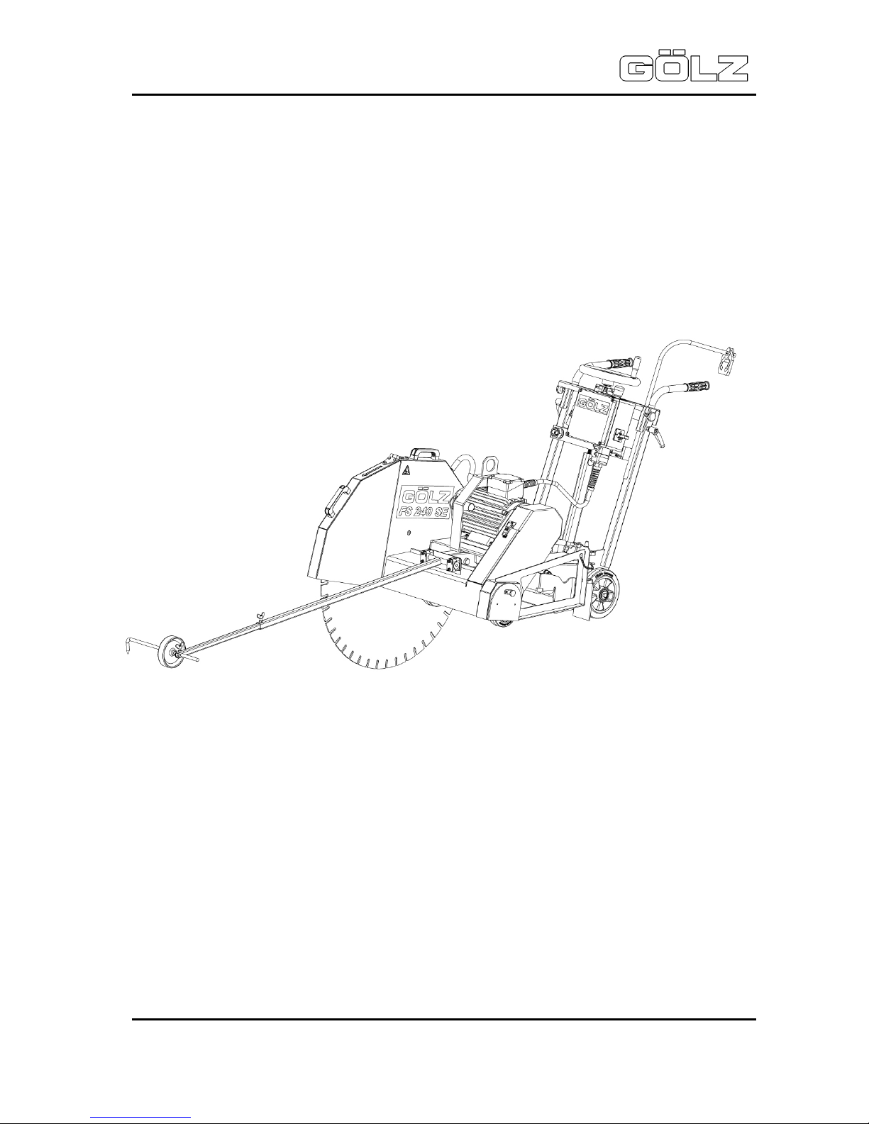
Floor saw
FS 240 SE
Art.-Nr. der Bedienungsanleitung: 02822410998
ZN der Bedienungsanleitung: 5006580-00
Erstellt am: 04 / 2012
Erstellt von: Julia Großart
Datei: K:\KDV\5006xxx\5006580-Bedienungsanleitung\
5006580-00-Bedienungsanleitung-doc.doc
GÖLZ GmbH
Dommersbach 51
53940 Hellenthal-Blumenthal
Telefon: (02482) 120
Telefax: (02482) 12135
Page 2
FS 240 SE
Operating instructions
- 2-
02822410998
5006580-00
EG-KONFORMITÄTSERKLÄRUNG
EC-DECLARATION OF CONFORMITY
DECLARATION DE CONFORMITE DE LA CE
Die Firma
Manufacturer
La Société
GÖLZ GmbH
Dommersbach 51, 53940 Hellenthal - Blumenthal
Tel.: (02482) 120 Fax: (02482) 12135
Erklärt in alleiniger Verantwortung, dass
folgendes Produkt:
FS 240 SE
Fugenschneider
Hereby certifies on it’s sole responsibility
that the following product:
FS 240 SE
Floor saw
Déclare sous sa seule responsabilité que
le produit suivant:
FS 240 SE
Scie de sol
Seriennummer / Serial number / Numéro de série: _______________________
Auf das sich diese Erklärung bezieht, mit
folgenden Richtlinien bzw. Normen übereinstimmt:
Maschinenrichtlinie 2006/42/EG
Sicherheits- und Gesundheitsanforderung
EMV-Richtlinie 2004/108/EG
Elektromagnetische Verträglichkeit
Richtlinie 2000/14/EG
Geräuschrichtlinie
Europäische Normen
EN 13862:2001
EN 13309:2000
EN 61000
DIN EN ISO 3744
Die oben genannte Firma hält Dokumentationen als Nachweis der Erfüllung
der Sicherheitsziele und die wesentlichen Schutzanforderungen zur Einsicht
bereit.
Which is explicitly referred to by this declaration meet the following directives
and standard(s):
Directive 2006/42/EC
Safety and health requirement
Directive
2004/108
/EC
Electromagnetic compatibility
Directive 2000/14/EC
Noise emission
European Standard
EN 13862:2001
EN 13309:2000
EN 61000
DIN EN ISO 3744
Documented evidence conforming with
the requirements of the Directive is kept
available for inspection at the above
Manufacturer's, address.
Qui fait l‘objet de la présente déclaration
correspond aux directives et normes
suivantes:
Directive 2006/42/CE
Prescriptions sanitaire et sécurité
Directive
2004/108
/CE
Compatibilité électromagnétique
Directive 2000/14/CE
Émission de bruit
Norme européenne
EN 13862:2001
EN 13309:2000
EN 61000
DIN EN ISO 3744
Pour faire foi de la conformité et du respect des règles de sécurité, la documentation peut être consultée au siège
de la Société susmentionnée.
Blumenthal, den 18.04.2012
Page 3

FS 240 SE
Operating instructions
- 3-
02822410998
5006580-00
Contents
1. Preface .......................................................................................................................... 4
2. General safety references.............................................................................................. 4
2.1 Basic operation and designated use of the machine .............................................................. 5
2.2 Organizational measures .................................................................................................... 5
2.3 Selection and qualification of person ................................................................................ 6
2.4 Normal operation of the machine ....................................................................................... 6
2.5 Special work related to the maintenance and repair of the machine ............................. 7
2.6 Information about special risks electrical energy ............................................................ 8
2.7 Noise ...................................................................................................................................... 8
2.8 Oils, greases and other chemical substances .................................................................. 8
2.9 Changing the location of the machine ............................................................................... 9
3. Description ...................................................................................................................10
3.1 Main parts ........................................................................................................................... 10
3.2 Technical data .................................................................................................................... 10
3.3 Safety devices .................................................................................................................... 11
4. Transport ......................................................................................................................12
4.1 Transport............................................................................................................................. 12
4.2 Storing ................................................................................................................................. 13
4.3 Bracket ................................................................................................................................ 13
5. Installation ...................................................................................................................14
5.1 Mounting the blade ............................................................................................................ 15
5.2 Water supply ....................................................................................................................... 16
5.3 Adjusting and operating elements ................................................................................... 17
5.4 Electric power supply ........................................................................................................ 17
5.5 Cutting operation ............................................................................................................... 17
6. Maintenance .................................................................................................................19
6.1 General ................................................................................................................................ 19
6.2 V-belts ................................................................................................................................. 19
6.3 Maintenance plan ............................................................................................................... 20
7. Troubleshooting ............................................................................................................21
8. Wearing parts ...............................................................................................................23
9. Spare parts list ..............................................................................................................24
10. Wiring diagram .............................................................................................................47
Page 4
FS 240 SE
Operating instructions
- 4-
02822410998
5006580-00
Jedes Umsetzen der Maschine außerhalb des Bereichs, in dem Schneidarbeiten durchgeführt werden, darf nicht mit
rotierendem Werkzeug durchgeführt werden!
It is not allowed to move the machine with rotating blade outside of the area in which cutting works have to be performed!
Tout déplacement de la machine doit s’opérer sans rotation de l’outil (risque de blessures) ceci est également valable sur
le chantier pour les déplacement entre coupes!
Vor Inbetriebnahme Betriebsanleitung lesen!
Read owner’s manual before the first initiation!
Lire la notice avant utilisation!
Wichtiger Hinweis!
Important advice!
Indication importante!
Achtung, spielende Kinder!
Be careful with kids on the work side!
Attention aux enfants!
Staubschutz tragen!
Wear dust protection!
Port de masque!
Achtung, Schneidgefahr!
Danger exist to cut oneself!
Attention danger de coupure!
Nicht berühren!
Never touch!
Ne pas toucher!
Gehörschutz tragen!
Wear ear muffs!
Protection acoustique obligatoire!
Schutzschuhe tragen!
Wear safety boots!
Chaussures de sécurite obligatoires!
Achtung, Schneidgefahr!
Danger exist to cut oneself!
Attention danger de coupure!
Schutzhelm tragen!
Wear safety helmet!
Port du casque!
Schutzkleidung tragen!
Wear safety clothes!
Vêtements protecteurs obligatoires!
Warnung vor elektrischer Spannung!
Electrical Hazard!
Attention tension électrique!
Augenschutz tragen!
Wear safety glasses!
Port de lunettes!
Schutzhandschuhe tragen!
Wear protective gloves!
Gants obligatoires!
Warnung vor allgemeiner Gefahr!
General danger!
Attention danger particulier!
1. Preface
Thanks for choosing a
GÖLZ
-product. This operating instruction is designed to familiarize the user
with the machine and its designated use.
The operating instruction contains important information on how to operate the machine safely, properly and most efficiently. Observing these instructions helps to avoid danger, to reduce repair costs
and downtimes and to increase the reliability and life of the machine. The operating instruction is to be
supplemented by the respective national rules and regulations for accident prevention and environmental protection. The operating instruction must always be available wherever the machine is in use.
This operating instruction must be read and applied by any person in charge of work with or on the
machine, such as:
• Operation including setting up, troubleshooting in the course of work, evacuation care and
disposal of fuels and consumables.
• Maintenance (servicing, inspection, repair) and/or
• Transport
In addition to the operating instructions and to the mandatory rules and regulations for accident
prevention and environment protection of the country and place of use of the machine, the generally
recognized technical rules for safe and proper working conditions and procedures must also be
observed.
2. General safety references
Page 5
FS 240 SE
Operating instructions
- 5-
02822410998
5006580-00
2.1 Basic operation and designated use of the machine
The machine has been built in accordance with state-of-the-art standards and the recognized safety
rules. Nevertheless, its use may constitute a risk to life and limb of the user or of third parties, or cause
damage to the machine and to other material property.
The machine must only be used in technically perfect condition in accordance with its designated use
and the instructions set out in the operating manual, and only by safety-conscious persons who are
fully aware of the risks involved in operating the machine. Any functional disorders, especially those
affecting the safety of the machine, should therefore be rectified immediately.
The machine is designed exclusively for sawing of abrasive building material. Using the machine for
purposes other than those mentioned above (such as for) is considered contrary to its designated use.
The manufacturer cannot be held liable for any damage resulting from such use. The risk of such
misuse lies entirely with the user.
Operating the machine within the limits of its designated use also involves observing the instructions
set out in the operating manual and complying with the inspection and maintenance directives.
2.2 Organizational measures
This operating manual must always be at hand at the place of use of the product and must be accessible to the person operating the machine!
In addition to this operating manual, all other generally applicable legal and other mandatory
regulations relevant to accident prevention and environmental protection must be observed! Such
obligations may also comprise the handling of hazardous materials, provisioning and/ or wearing of
personal protective equipment, or road traffic regulations. This operating manual must be supplemented by instructions covering the duties involved in supervising and notifying special organizational
features, such as job organization, work flows or the person entrusted with the work.
Person entrusted with work on the product must have read the operating manual prior to taking up
work. This applies especially to persons working only occasionally on the product, e.g. during set-up
or maintenance activities. Check - at least from time to time - whether the personnel are carrying out
the work in compliance with the operating manual and paying attention to risks and safety-relevant
factors.
For reasons of safety, long hair must be tied back or otherwise secured, garments must be closefitting and no jewellery - including rings - may be worn. Severe injury may result from being caught by
moving parts of the machine. Personal protective equipment must be used wherever required by the
circumstances or by law (e.g. safety glasses, ear protectors, safety boots, suitable safety clothing).
Observe the regulations for prevention of accidents! Observe all safety precautions and warnings
attached to the product and always keep them in good and perfectly legible condition.
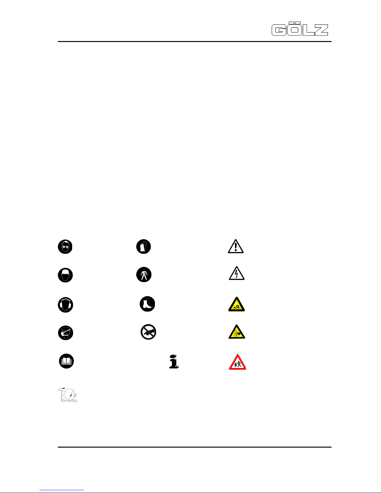
The personal protection equipment should consist of the following parts:
1 Helmet with protection of the ears
2/3 Visor or safety glasses / Dust mask
4 Protective gloves
5 Safety clothes
6 Safety boots
Page 6

FS 240 SE
Operating instructions
- 6-
02822410998
5006580-00
In case event of safety-relevant modifications or changes in the behaviour of the product, stop the
product immediately and report the malfunction to the competent authority/ person.
Do not remove or make inoperative any safety devices the product is equipped with.
Never make any modifications, additions or conversions which might affect safety without the
manufacturer’s / distributor’s prior approval! This also applies to the installation and adjustment of
safety devices as well as to welding and drilling work on supporting structures.
Damaged or worn parts of the product must be replaced immediately. Use genuine spare parts only.
All spare parts and tools must comply with the technical requirements specified by the manufacturer/
distributor.
Adhere to the legally prescribed preventive maintenance and inspection intervals or those specified in
this operating manual!
All maintenance and repair activities must be performed by qualified personnel using suitable tools
and other suitable workshop equipment.
Observe the fire alarm and fire fighting measures. The personnel must be made familiar with the
location and handling of fire extinguishers!
2.3 Selection and qualification of person
Any work on and with the product must be executed by reliable person only. Statutory minimum age
limits must be observed!
The product must be operated or serviced by trained or properly instructed person only. Clearly define
the individual responsibilities of the person for operation, set-up, maintenance and repair.
Make sure that only authorized work on or with the product.
Define the machine operator’s responsibilities -also with regard to observing road traffic regulations-,
providing the operator with the authority to refuse instructions by third parties that are contrary to
safety.
Do not allow persons to be trained or instructed or persons taking part in a general training course to
work on or with the product without being permanently supervised by an experienced person.
Work on the electrical system and equipment of the product must be carried out only by a skilled
electrician or by properly instructed persons working under the supervision and guidance of a skilled
electrician and in accordance with electrical engineering rules and regulations.
2.4 Normal operation of the machine
Before beginning work, familiarize yourself with the surroundings and circumstances of the site, such
as obstacles which might impede work or traffic, the soil bearing capacity and the required safety
measures, e.g. barriers separating the work site from public traffic.
Avoid any operational mode that might be prejudicial to safety. Check the range in gas-, water- and
power supply lines before working.
Take the necessary precautions to ensure that the machine is used only when in a safe and reliable
state. Operate the machine only if all protective and safety-oriented devices, such as removable
safety devices, emergency shut-off, sound-proofing elements and exhausters, are in place and fully
functional.
Check the machine at least once per working shift for obvious damage and defects. Report any
changes to the competent person immediately. If necessary, stop the machine immediately and lock it.
In the event of malfunctions or changes in the machine’s behaviour, stop the product immediately and
secure it against restarting. Have any defects rectified immediately!
Take precautions to ensure that the operator always has an adequate view of the work. Before leaving
the machine always secure it against inadvertent movement and unauthorized use!
Cutting has to be operated wet in order to prevent the occurrence of harmful particulate matter and to
increase the lifetime of the cutting tool.
During start-up and shut-down procedures always watch the indicators in accordance with the
operating instructions.
Page 7

FS 240 SE
Operating instructions
- 7-
02822410998
5006580-00
Noise protection equipment on the machine has to be in protective position during operation. Wear the
prescribed personal ear protection!
Avoid any operation that might be a risk to machine stability. Always keep at a distance from the
edges of building pits and slopes.
The machine is designed for use in daylight! The machine operator/ owner must ensure sufficient
workplace lighting for non-illuminated work sites!
Before leaving the machine always secure the machine against inadvertent movement and
unauthorized use.
2.5 Special work related to the maintenance and repair of the machine
Observe the adjustment, maintenance and inspection activities and intervals set out in the operating
manual, including information on the replacement of parts or assemblies! These activities may be
performed by skilled personnel only.
Brief the operating personnel before initiating special repair or maintenance activities. Appoint a
person to supervise such activities. In any work concerning the operation, adaptation to production
requirements, conversion or adjustment of the machine and it’s safety-oriented devices or any work
related to inspection, maintenance and repair, always observe the start-up and shut-down procedures
described in the operating manual as well as the instructions on maintenance activities!
If necessary, secure a large area around the location where maintenance of the machine is to be
performed. Maintenance and repair work may be carried out only if the machine is placed on level and
solid ground and secured against inadvertent movement.
If the machine is completely shut down for maintenance or repair work, it must be secured against
inadvertent restarting.
When using a lifting gear for replacing individual parts or large assemblies make sure that the parts/
assemblies are carefully attached to the lifting gear and secured in place to avoid hazardous
conditions. Use only suitable and technically perfect lifting gear and suspension systems with
adequate lifting capacity! Never work or stand under suspended loads! The fastening of loads and the
instructing of crane/industrial truck operators should be entrusted to experienced persons only!
The instructor must be within sight or sound of the operator. Use an intercom system if necessary.
When carrying out overhead work always use specially designed or other safety-oriented ladders and
working platforms. Never use machine parts as a climbing aid!
Wear a safety harness when performing maintenance work at greater heights! Keep all handles, steps,
handrails, platforms, landings and ladders in a clean condition!
Before performing any maintenance/ repair activities clean the machine, especially the connectors and
screwed joints, and remove any oil, dirt and preservative agents. Never use aggressive detergents!
Use lint-free cleaning rags!
Before cleaning the machine with water or other cleaning agents cover or tape up all openings which for safety and functional reasons- must be protected against the ingress of water/ steam/ cleaning
agents. Special care must be taken with bearings, electric motors and electronic systems. After
cleaning, make sure to remove all covers/ tapes from the openings.
After cleaning, check all cables for leaks, loose connections, chafe marks and damage! Have any
defects found rectified immediately! Always retighten any screwed connections that have been
loosened during maintenance/repair activities!
Any safety devices removed for set-up, maintenance or repair purposes must be refitted and checked
immediately upon completion of the set-up, maintenance or repair work.
Avoid any operation that might affect the stability of the machine. Always keep a sufficient distance
from the edges of excavations, ditches and slopes!
Before leaving the machine always secure it against inadvertent movement and unauthorized use!
Ensure that all process materials and replaced parts are disposed of safely and with minimum environmental impact!
Page 8

FS 240 SE
Operating instructions
- 8-
02822410998
5006580-00
2.6 Information about special risks electrical energy
Observe the relevant national regulations or standards. Electrical connections must always be kept
free from dirt and moisture. Use only original fuses with the specified rating! Switch off the machine
immediately, if trouble occurs in the electric power supply!
When working with the machine, maintain a safe distance from overhead electric lines. If work is to be
carried out close to overhead lines, the working equipment must be kept well away from them.
Caution, danger! Check out the prescribed safety distances.
If your machine comes into contact with a live wire:
• warn others against approaching and touching the machine
• have the live wire de-energized
Work on the electrical system or equipment may only be carried out by a skilled electrician himself or
by specially instructed personnel under the control and supervision of such electrician and in
accordance with the applicable engineering rules. If provided for in the regulations, the power supply
to parts of machines and plants, on which inspection, maintenance and repair work is to be carried out
must be cut off. Before starting work, check the de-energized parts for the presence of power and
ground or short-circuit them in addition to insulating adjacent live parts and elements.
The electrical equipment of machines is to be inspected and checked at regular intervals. Defects
such as loose connections or scorched cables must be rectified immediately.
Necessary work on live parts and elements must be carried out only in the presence of a second
person who can cut off the power supply in case of danger by actuating the emergency shut-off or
main power switch. Secure the working area with a red-and white safety chain and a warning sign.
Use insulated tools only.
If mobile electrical equipment, connecting cables and/ or extension/ appliance cords with plug
connectors are used, ensure that such equipment, cables and cords are checked for correct function
at least once every six months by a qualified electrician or - if suitable testing equipment is available by a properly instructed person.
Protective installations with fault-current protection units used in non-stationary equipment must be
checked for correct operation at least once a month by a properly instructed person.
Fault-current and fault-voltage protection units must be checked for correct operation by actuating the
testing facility:
• once on every working day in the case of mobile equipment,
• at least once every six months in the case of stationary equipment.
2.7 Noise
Noise Protection devices on the machine must be in the protection position during operation!
Always wear the specified personal hearing protection (UVV 29 §10)!
2.8 Oils, greases and other chemical substances
When handling hydraulic fluids, lubricating fluids, greases or preservatives (called operating materials
and lubricants in the following), the safety regulations applicable for the respective product must be
observed! Avoid prolonged contact of operating materials and lubricants with the skin!
The skin must be carefully cleaned of adhering operating materials and lubricants!
Exercise caution when handling hot operating materials and lubricants, as there is a danger of burns
or scalding. Particularly at liquid temperatures above 60°C, avoid any skin contact with these liquids!
If operating materials or lubricants get into the eyes, flush thoroughly with drinking water. Then visit a
doctor! Immediately clean up any operating materials and lubricants which have leaked out. Use
absorbent material for this purpose!
Operating materials or lubricants must not be allowed to seep into the soil or to get into the public
sewerage system!
Page 9
FS 240 SE
Operating instructions
- 9-
02822410998
5006580-00
Properly collect, store and dispose of operating materials and lubricants which can no longer be used!
Observe and follow the respective applicable laws and regulations for handling operating materials
and lubricants and their disposal in the country in which these substances are used! Obtain
information from the responsible agencies!
2.9 Changing the location of the machine
Use only suitable means of transport and lifting gear of sufficient capacity when loading or transporting
the machine! Appoint an experienced instructor for the lifting operation!
Always observe the instructions given in the operating manual when lifting the machine (use only the
prescribed lifting eyes for attaching the lifting gear)! Use only suitable transport vehicles with sufficient
load capacity! Secure the load carefully. Use suitable fastening points for securing!
Before loading the machine or parts of it, secure the machine/ parts against inadvertent movement!
Attach a suitable warning sign!
Before using the machine again, make sure that such protection material or devices are properly
removed! Parts which had to be removed for transporting of the machine must be refitted and secured
carefully before the machine is used again! Even when the transport of the machine only involves a
minor relocation, disconnect it from all external power supply lines!
Before using the machine again, make sure that the connection to such external supply lines is reestablished properly. The recommissioning procedure must be strictly in accordance with the operating manual! Observe the instructions given in the operating manual when reassembling and operating
the machine. Before setting the machine in motion always check that all accessories are safely
stowed.
Note that a non-fixed but mounted and standing machine will fall forward.
While carrying heavy weights, avoid stooping down.
Page 10

FS 240 SE
Operating instructions
- 10-
02822410998
5006580-00
3. Description
Operate the machine only using tools in accordance with the manufacturer’s instruction. Using other
tools is considered contrary to its designated use. The manufacturer cannot be held liable for any
damage resulting from such use. The risk of such misuse lies entirely with the user.
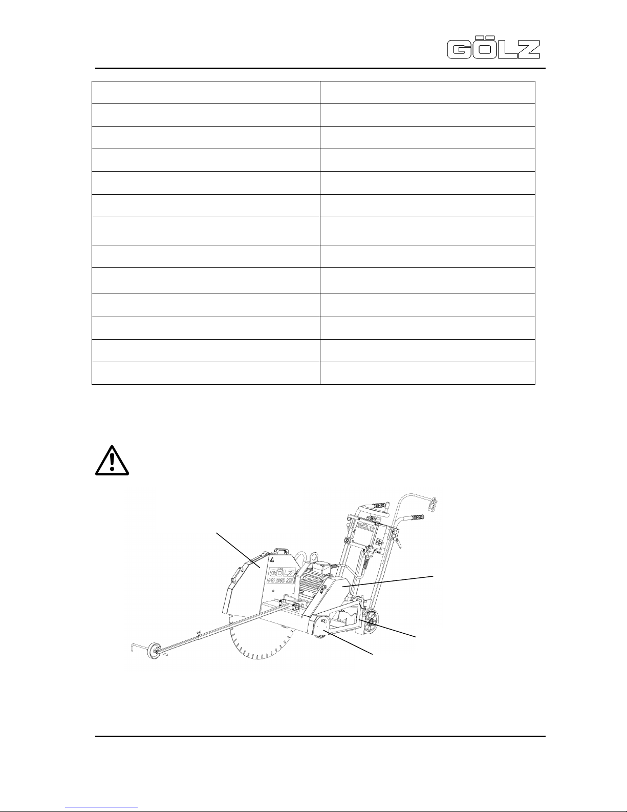
3.1 Main parts
1. Control panel 7. Electric motor 12. Water connection
2. Chassis 8. Switch box with 13. Eyebolt and
3. Undercarriage electrical connection Engine bracket
4. Flange guard 9. Blade guard 14. Blade guard pulley
5. Pointer unit 10. Connecting rod
6. Blade 11. Strain relief
3.2 Technical data
Max. cutting depth 330 mm - 13 in.
Max. blade-Ø 800 mm - 31,5 in.
Flange size Ø 120 mm - 4,7 in.
Blade shaft size Ø 25,4 mm - 1 in.
Engine
3-phases-motor
7,5kW (10 HP), 14,4 A
3
8
13
5
9
10
6 2
12
Page 11
FS 240 SE
Operating instructions
- 11-
02822410998
5006580-00
Max. cutting speed with blade 60 m/s
Engine shaft speed 2860 rpm
Blade shaft speed 1430 rpm
Feed Manual
Excavation Manual (hand crank)
Cutting depth control Scale on frame
Water supply Connection for external water supply
V-belt tension Manual
Dimensions (L x W x H)
approx. 1650 x 733 x 989 mm - 65 x 28,9 x
178,7 in.
Weight (without water tank and blade) ca. 187 kg - 415,5 lbs.
Sound power level after DIN ISO 6393
No load = 100 dB(A)
Full load = 119 dB(A)
Sound pressure level after DIN ISO 6393
No load = 80 dB(A)
Full load = 100 dB(A)
Vibration after ISO 5349 VDMA 03/2006 a = 3,7 m/s²
3.3 Safety devices
Danger: During cutting or displacing the machine, all safety devices shown below
must be mounted!
Blade guard for
max. blade size of
Ø 800 mm - 31.5 in.
with blade shaft protection
V-belt
guard
Flange guard
Blade shaft protection
Page 12
FS 240 SE
Operating instructions
- 12-
02822410998
5006580-00
4. Transport
Danger of down coming parts!
Injury hazard: Sharp edges!
4.1 Transport
Before transport the emergency stop switch is to be pressed and the brake is to be actuated.
Dismount the blade and attach again the blade guard. Lower the machine until the end stop. Check
that all parts of the machine are well fastened before transporting. After loading the machine is to be
secured with suitable lashing material.
For loading only use lifting gear and tackle of sufficient capacity (Allow the kerb
weight of the machine).
Lift the machine using the lifting eye.
Danger: Only use the lifting eye for lifting the machine!
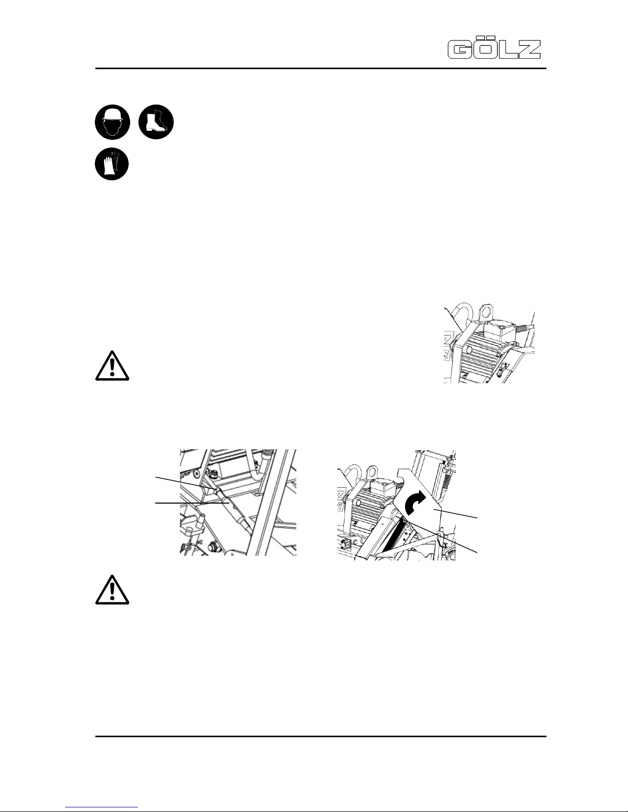
To make transport easier, the motor can be removed together with the motor bracket.
Loosen the lock nut M10 (Pos.1) and turn the turnbuckle nut (Pos. 2) off. Open the V-belt protective
hood (Pos. 3) in order to remove the V-belt (Pos. 4) from the V-belt pulley of the motor.
Caution: The motor bracket can tilt!
Loosen the hexagonal nut M16 (Pos. 5) and remove the washer (Pos. 6). Disconnect the motor plug
(Pos. 7) from the switch box.
Position the pushing rods (Pos. 8) in the collets of the motor bracket and secure them with the pipe
locking pins (Pos. 9).
3
4
2
1
Page 13
FS 240 SE
Operating instructions
- 13-
02822410998
5006580-00
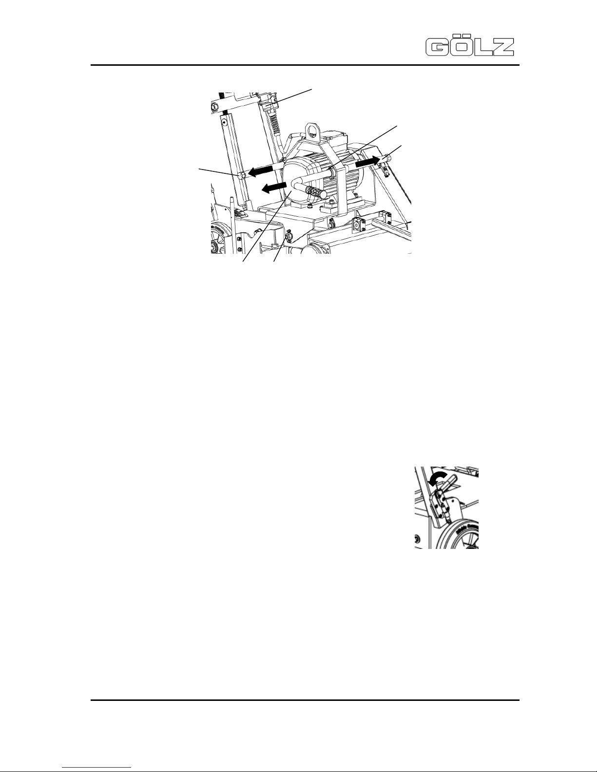
The motor (Pos. 10) can now be removed sideways from the axes over the pushing rods together with
the motor bracket and be carried by two people.
For mounting, proceed in reverse order. After mounting, ensure the correct V-belt tension!
4.2 Storing
Store the machine in a dry, high or locked place, out of the reach of children or unauthorized persons.
Clean and preserve the machine with corrosion preventive if storing over a longer time like winter time!
4.3 Bracket
When the machine is not in use, the brake is to be actuated as a matter of
principle.
9
10
8
7
5
/ 6
8
Page 14
FS 240 SE
Operating instructions
- 14-
02822410998
5006580-00
5. Installation
Information: Unconditional observe the owner’s manual of the engine manufacturer!
Danger: Never touch rotating parts like blade shaft or blade while operating!
Danger: Rotating parts may pull in clothing! Wear tightly clothing!
Danger: Down coming parts can cause injuries to the operator!!
Place the machine on an even, firm and stable ground. Have the working area well lightened. Keep
the working area clean, cluttered areas invite injuries. Observe the manufacturer’s information for
connecting power and water supply. Lay all lines or cables that damages will be prevented.
Mount the blade to the manufacturer’s odds (Observe the min. flange-Ø; use only original screws or
nuts). Use only blade diameters which are allowed by the manufacturer.
The working area is reserved only for the operator. Keep unauthorized persons out of the working
area. Make sure the operator always has well sight to the working area. He always has to intervene in
the working process.
Never operate the machine without mounted safety devices. Check the blade is well fastened before
beginning to operate. Check the correct water flow to the blade. If harmful or explosive stuffs like dust,
milk-of-lime arise while cutting, observe local regulations.
If there is a risk that, during the cutting process, material particles can be accelerated outwards, wear
safety goggles.
Danger: Demolition parts can cause injuries to the operator while cutting!
When travelling on public roads, ways and places always observe the valid traffic regulations and, if
necessary, make sure beforehand that the machine is in a condition compatible with these regulations.
After operating secure the machine against unintentional moving. If there is a risk due to increased
noise exposure during the cutting process at the workplace, wear ear protection.
Danger: The sound pressure may exceed 85 dB(A)!
Appropriate to the application of the machine it could be necessary to wear further protective equipment.
Danger: Down coming parts at the building site can cause injuries to the operator!
Page 15

FS 240 SE
Operating instructions
- 15-
02822410998
5006580-00
5.1 Mounting the blade
In the cutting speed range all used blades must be designed for the max. rpm of the machine. Never
use faulty or damaged blades.
Danger: Damaged cutting discs can cause serious personal injury!
Note: Wrong direction of rotation leads to drastically increased wear of the cutting disc!
Danger: Wrong direction of rotation can result in the detachment of a segment of the
cutting disc and thus cause serious personal injury!
Depending on the material to be machined, the machining process and the nature of work to be
carried out, use the cutting discs according to manufacturer's / supplier's specifications.
Note: Before mounting the cutting disc, thoroughly clean all the fastening elements relating to the cutting disc such as flanges, threads of the cutting shaft,
screws or nuts!
Each time a cutting disc is mounted or changed, the joint cutter is to be shut down first and the
emergency stop switch is to be pressed or to be disconnected from any energy source.
Pull out the spring cotter pin (Pos. 2) so that you
can remove the cutting disc guard (Pos. 1) from
the machine. Clean the inner flange (3) before
mounting the blade.
Mount the cutting disc (max. Ø 800 mm, Pos. 4) with the correct
mounting holes (Ø 25.4 mm)
Make sure that the rotational direction is correct! There are
directions of rotation arrows on the cutting disc guard as well as
on the cutting disc itself.
Fit the outer cutting flange (Pos. 5) and secure it with screw M
16 (Pos. 6) SW 24.
In the cutting shaft, there is a left-hand thread in the direction of
motion on the right; in the direction of motion on the left, there is
a right-hand thread.
6
5
4
1
3
2
Page 16

FS 240 SE
Operating instructions
- 16-
02822410998
5006580-00
After mounting, fit the cutting disc guard again and fit the spring
cotter pin again to its mounting hole. Make sure that the guard
plate cutting shaft (Pos. 7) is in position.
5.2 Water supply
Screw the connecting piece (Pos. 1 SW26) of the water hose of the cutting
disc guard to the double nipple (Pos. 2 SW39) on the control panel.
Connect, with the help of a GEKA-coupling, the existing coupling (Pos. 3)
on the right operator's side of the machine. Make sure that the mini ball
valve (Pos. 4) is closed (valve lever in 90° position to the flow direction).
The water supply connection of the wall-flush hood is the same as the
connection of the cutting disc guard.
Please note that, for left-hand or right hand cutting, the water connection of the
water-flush hood is to be changed accordingly (SW39 and SW26).
1
7
1 2
3
4
Connection
Control Panel
Connection
Right Cut
Connection
Left Cut
Page 17

FS 240 SE
Operating instructions
- 17-
02822410998
5006580-00
5.3 Adjusting and operating elements
1. CEE-plug
2. star-delta connection switch
3. Emergency stop switch
4. Main emergency stop switch
5. Connection motor cable
5.4 Electric power supply
Ensure power-supply matches with details from motor rating-plate:
• Input voltage: V / 50 Hz,
• Fuse protection: A
The used power supply has to conform the instructions of assembly for construction site (ACS) (Error
current protective circuit, who works until max. 30 mA by main error current).
Only use extension cable with protective conductor (5-wire) and
adequate wire cross section (min.
4mm²). Always unwind the whole cable roller.
Connect the motor cable (Pos. 1) by means of the plug-in
system to the switch box (Pos. 2)
Before you connect the power plug of the cable to the appliance
inlet (Pos. 3) of the machine, the emergency stop switch (Pos.
4) must be pressed.
Make sure that the star-delta connection switch is turned to "0"
and that the main emergency switch is turned to "Off".
After you have connected the power supply unit to the machine,
the emergency stop switch (Pos. 4) is to be unlocked. Attach the
cable to the strain-relief clamp (Pos. 5).
The strain-relief clamp is two-sided pluggable in the control
panel and can be adjusted angularly by means of the star grip.
5.5 Cutting operation
Danger: Operating with too high feed the machine might rise out of cut! In
emergency situations shut down the machine immediately by pushing the
emergency shut-off!
Each relocating of the machine between sawing operations has to be carried out
with non-rotating cutting disc, i.e. when the drive motor is idle.
Before starting the cutting operation, the water supply is to be connected according to section 5.2
"Water Supply", the cutting disc is to be mounted according to section 5.1 "Mounting the blade" and
the power supply is to be connected according to section 5.4 "Power Supply".
4
2
5
3
1
5
4
3
2 1
Page 18

FS 240 SE
Operating instructions
- 18-
02822410998
5006580-00
In order to ensure trouble-free motor start, raise the machine, before you start it, by means of the hand
crank (Pos. 4) to such extent that the cutting disc has no soil contact.
Then turn the main emergency stop switch (Pos. 1) from "Off" to "On". To start the motor, turn the stardelta connection switch (Pos.. 2) from "0" to "Star" and wait until the motor has reached its full speed.
Make sure that the rotational direction of the cutting disc is correct! As the circumstances require, the
rotational direction of the drive motor is to be reversed. Turn the star-delta connection switch (Pos. 2)
again to "0", press the emergency stop switch (Pos. 3) and pull off the power plug.
With a suitable screwdriver, the phase inverter in the appliance inlet can be turned. Connect the power
supply unit to the machine again, as described above, and start the machine again.
As soon as the motor has reached its full speed and full power, the star-delta connection switch (Pos.
2) can be turned from "Star" to "Triangle".
Before you lower the machine by means of the hand crank (Pos. 4), the mini ball valve (Pos. 5) is to
be opened. Lower the machine to such extent that you reach the desired cutting depth (Cutting Depth
Label). Pull then the indexing plunger (Pos. 6) on the control panel, so that it snaps into the catch disk
in order to fix the desired cutting depth.
Work with a steady feed pressure. Too high feed pressure leads to an overload of the motor and there
is the risk that the machine loses contact with the ground. Too low feed pressure can polish the
segments and make them blunt.
After the cutting operation raise the machine again by means of the hand crank (Pos. 4). Stop the
water feed, turn the star-delta connection switch (Pos. 2) again to "0".
Before transporting the machine, before changing the cutting disc or doing maintenance work, the
emergency stop switch (Pos. 3) is also to be pressed and the main emergency stop switch (Pos. 1) is
to be turned to "Off".
6
5
3 2
1
4
Page 19

FS 240 SE
Operating instructions
- 19-
02822410998
5006580-00
6. Maintenance
6.1 General
Information: Clean the machine after every operation. Observe local environmental
regulations!
For your security and for a trouble-free operation of the machine, professional care and maintenance
is indispensable.
Maintenance and repair work is, as far as possible, generally to be carried out when the machine is
shut down and the power plug pulled off. For maintenance jobs which must be done while the floor
saw is running, the blade has to be dismounted before beginning the job. Electrical work is only to be
carried out by skilled electricians.
In accordance to the given cycles, the subsequently described maintenance work has to be enforced.
Also the wearing parts subject to no certain maintenance-intervals have to be checked regularly for
wear and to adjust if necessary or to exchange. With I.C. engines, the maintenance work has to be
enforced in accordance with the separate maintenance-instruction of the engine manufacturer.
Before each
start-up
After work
Once a week
Once a year
In case of failure
In case of damage
Complete machine
Visual inspecion
(condition, ab-sence
of leaks)
X X X
Clean
X
Flange and blade
acceptance
Clean
X
V-belts
Check
X
X
X X
Replace
X
Water nozzle and
feeding hoses
Clean
X X
Tools Check
X X X
6.2 V-belts
The multiple V-belt and the V-belt drive are retightened manually.
Loosen the counter nut M10 (Pos. 1) and turn the turnbuckle nut (Pos.
2) allowing you to tighten the motor and the multiple V-belt. Tighten the
counter nut M10 (Pos. 1) again.
2
1
Page 20

FS 240 SE
Operating instructions
- 20-
02822410998
5006580-00
To make it easier to change the multiple V-belt, raise the machine slightly by means of the hand crank.
Before you continue to work, press the emergency stop switch and pull off the power plug.
Loosen the counter nut M10 (Pos. 1) and slightly turn off the turnbuckle nut (Pos. 2) in order to remove
the tension from the multiple V-belt.
Remove the flange protection (Pos. 3) and open the V-belt protective hood (Pos. 4) in order to remove
the loosened multiple V-belt (Pos. 5) from the V-belt pulleys.
Position the new multiple V-belt on the V-belt pulleys and tighten it by turning the turnbuckle nut (Pos.
1) in the opposite direction until the required V-belt tension is reached. Tighten the counter nut (Pos.
2) again.
Shut the V-belt protective hood again and fit the flange protection again. If during operation, the V-belt
tension decreases to such extent that there is a slip between the multiple V-belt and the V-belt pulleys,
the multiple V-belt must be retightened.
6.3 Maintenance plan
1. Flange bearing of the spindle shaft: Clean from time to time, lubricate.
2. Shaft: Clean from time to time, lubricate.
3
5
4
Page 21

FS 240 SE
Operating instructions
- 21-
02822410998
5006580-00
7. Troubleshooting
Attention: In the event of changes in the behaviour of the machine during operation,
stop the machine immediately and report the malfunction to the competent authority
/ person!
Problem Cause Remedy
Engine
Engine does not run!
Power plug is not properly
connected
Check for correct connection
Fuses (from ACS or machine) have
triggered
Check fuses
Malfunction on electric installation
Electric installation needs to
be checked by a qualified
person
Lowering
Joint cutter can neither be
lowered nor be raised
Undercarriage or threaded spindle
tight.
Check undercarriage and
threaded spindle
Cutting
Machine rises out of cut
Dull diamond blade
Sharpen or use softer
diamond blade
Feed too high Reduce feed
Non circular abrasion of the
diamond blade
Damaged centering of the blade
shaft
Replace blade shaft
Warped blade shaft Replace
Loose or damaged blade shaft
bearings
Tighten or replace
Diamond blade jams in the cut
No free cut because of sideward
wear-out of segments
Check hoses for fracture free
laying
Damaged diamond blade core Replace diamond blade
Abnormal wear-out of
segments
Insufficient water flow
Check hoses for fracture free
laying
Wrong type of diamond blade
Choose different diamond
blade
Feed too high Reduce feed
Cutting in loose underground Reduce cutting depth
Bad cutting performance
Slippy V-belts Adjust
Blunt diamond blade
Sharpen or use softer
diamond blade
Page 22

FS 240 SE
Operating instructions
- 22-
02822410998
5006580-00
Page 23

FS 240 SE
Operating instructions
- 23-
02822410998
5006580-00
8. Wearing parts
Wearing parts for construction devices mentioned in the operating manual
such as drilling and sawing machines
Wearing parts are the parts subject to operation-related (natural) wear during proper use of the device.
The wearing time cannot be uniformly defined, and differs according to the intensity of use. The
wearing parts must be adjusted, maintained and, if necessary, replaced for the specific device in
accordance with the manufacturer’s operating manual. Operation-related wear is not a reason for
defect claims.
• Feed and drive elements such as toothed racks, gearwheels, pinions, spindles, spindle
nuts, spindle bearings, cables, chains, sprockets, belts
• Seals, cables, hoses, packings, connectors, couplings and switches for pneumatic, hydraulic,
water, electrical and fuel systems
• Guide elements such as guide strips, guide bushes, guide rails, rollers, bearings, sliding
protection supports
• Clamping elements for quick-separating systems
• Flushing head seals
• Slide and roller bearings that do not run in an oil bath
• Shaft oil seals and sealing elements
• Friction and safety clutches, braking devices
• Carbon brushes, commutators/armatures
• Easy-release rings
• Control potentiometers and manual switching elements
• Securing elements such as plugs, anchors, screws and bolts
• Fuses and lamps
• Auxiliary and operating materials
• Bowden cables
• Discs
• Diaphragms
• Spark plugs, glow plugs
• Parts of the reversing starter such as the starting rope, starting pawl, starting roller and
starting spring
• Sealing brushes, rubber seals, splash protection cloths
• Filters of all kinds
• Drive rollers, deflection rollers and bandages
• Cable anti-twist elements
• Running and drive wheels
• Water pumps
• Cut-material transport rollers
• Drilling, parting and cutting tools
• Energy storage
Wearing parts of this machine are grey marked in the spare parts list.
Page 24

FS 240 SE
Operating instructions
- 24-
02822410998
5006580-00
9. Spare parts list
So bekommen Sie schnell und richtig Ihr Ersatzteil
- für Maschine - Modell - Masch.-Nr.
- Artikelnummer - Bezeichnung des Ersatzteiles
- Anzahl der gewünschten Ersatzteile
- Wohin liefern?
- Womit liefern (Post, Eilpost etc.)?
Always indicate:
- machine/model/serial number
- item number and description of the spare part
- amount of spare parts desired
- full address
- goods to be sent by regular mail, express, etc.
Pour obtenir rapidement les pièces de rechange indiquer :
- Nº de la machine, du modèle
- Nº de l’article / description de la pièce désirée
- Nombre de pièces commandées
- Adresse de livraison
- Mode de livraison (poste, express etc...)
Page 25

FS 240 SE
Operating instructions
- 25-
02822410998
5006580-00
Page 26

FS 240 SE
Operating instructions
- 26-
02822410998
5006580-00
Pos. Artikelnummer Menge Norm Info Benennung Description Désignation
1
0282 241 0087
1 Bedienpult Control panel Pupitre de commande
2
0282 241 0001
2
Ø 200 x 60
x Ø 25
Rad Wheel Roue
3
0298 900 0010
2
DIN EN
ISO 7093
A 10,5 Scheibe Washer Rondelle
4
0295 000 0187
2
DIN EN
ISO 4017
M 10 x 20 Schraube Screw Vis
5
0298 900 0008
1
DIN EN
ISO 7093
A 8,4 Scheibe Washer Rondelle
6
0282 241 0026
1 Lagergehäuse Bearing housing Logement du palier
7
0282 241 0012
2 Ø 30 Gleitfolie Sliding film Glissière
8
0282 241 0013
4
DIN EN
ISO 4762
M 6 x 80 Schraube Screw Vis
9
0281 045 0027
4
DIN EN
ISO 7040
M 6 Mutter Nut Écrou
10
0282 240 0022
1
UCFL 204
Ø 20
Flanschlager Flange bearing Roulement avec flasque
11
0285 300 0018
2
DIN EN
ISO 4017
M 12 x 45 Schraube Screw Vis
12
0285 300 0015
2
DIN EN
ISO 7040
M 12 Mutter Nut Écrou
13
0282 241 0106
1 Tr 20 x 4 Spindel Shaft Fuseau
14
0282 250 0020
4 DIN 471 20 x 1,2 Sicherungsring Circlip Circlip
15
0282 241 0020
1 DIN 6885 6 x 6 x 14 Passfeder Key Clavette
16
0282 241 0008
1 Rastscheibe Locking disc Rondelle d’arrêt
17
0282 241 0101
1 Handrad Handwheel Volant
18
0282 150 0035
1
DIN EN
ISO 4017
M 8 x 20 Schraube Screw Vis
19
0295 230 0013
1 Federriegel Locking bar Boulon d’arrêt
20
0295 230 0032
1
DIN EN
ISO 8675
M 20 x 1,5 Mutter Nut Écrou
21
0282 241 0068
1 Bremse Bracket Frein
22
0285 300 0142
1
DIN EN
ISO 4032
M 6 Mutter Nut Écrou
23
0295 000 3530
1
DIN EN
ISO 4017
M 6 x 16 Schraube Screw Vis
24
0282 250 0321
4
DIN EN
ISO 4762
M 5 x 10 Schraube Screw Vis
25
0295 600 0533
1 DIN 6885 5 x 5 x 12 Passfeder Key Clavette
26
0282 250 0105
4
DIN EN
ISO 7090
B 13 Scheibe Washer Rondelle
27
0295 600 1034
1
DIN EN
ISO 4026
M 6 x 30 Gewindestift Grub screw Vis sans tête
o.A.
0295 899 0273
1
Umplatzieren
Aufkleber Label Macaron
o.A.
0295 899 0033
1
Piktogramme
Aufkleber Label Macaron
o.A.
0295 899 0228
1 LWA111dB Aufkleber Label Macaron
o.A.
0282 241 0076
1 Typenschild Label Plaque d’identification
Page 27

FS 240 SE
Operating instructions
- 27-
02822410998
5006580-00
Page 28

FS 240 SE
Operating instructions
- 28-
02822410998
5006580-00
Pos. Artikelnummer Menge Norm Info Benennung Description Désignation
1
0282 241 0002
2
Ø 20 Kompaktbuchse Bushing Douille
2
0282 241 0003
2
Gehäuselager Bearing housing Logement du palier
3
0282 241 0004
1
Chassis Chassis Châssis
4
0298 900 0008
8
DIN EN
ISO 7093
A 8,4 Scheibe Washer Rondelle
5
0282 150 0036
4 DIN 127 A 8 Federring Spring washer Rondelle-ressort
6
0282 250 0073
8
DIN EN
ISO 4017
M 8 x 25 Schraube Screw Vis
7
0281 045 0027
6
DIN EN
ISO 7040
M 6 Mutter Nut Écrou
8
0282 252 0142
1
ZSB-Scharnier Hinge Charnière
9
0295 000 3530
6
DIN EN
ISO 4017
M6 x 16 Schraube Screw Vis
10
0282 241 0044
1
Keilriemenschutzhaube
Blade guard pulley
Capot de protection
poulie
11
0282 241 0046
1
Spannverschluss Fastener Tendeur
12
0267 112 5636
4
DIN EN
ISO 1207
M 4 x 16 Schraube Screw Vis
13
0267 112 5646
4 DIN 127 A 4 Federrring Spring washer Rondelle-ressort
14
9210 260 0600
4
DIN EN
ISO 4032
M 4 Mutter Nut Écrou
15
0282 241 0047
2 Spritzschutz Splash guard
Protection contre le
réfrigérant
16
0282 065 0005
4
DIN EN
ISO 7040
M 8 Mutter Nut Écrou
17
0282 241 0110
1 Schnitttiefenanzeige Scale acceptance Logement gamme
18
0282 250 0006
4
DIN EN
ISO 7090
B 8,4 Scheibe Washer Rondelle
19
0286 570 0069
4
DIN EN
ISO 7090
B 6,4 Scheibe Washer Rondelle
20
0285 300 0142
2
DIN EN
ISO 4032
M 6 Mutter Nut Écrou
21
0295 000 0152
2
DIN EN
ISO 4017
M 6 x 25 Schraube Screw Vis
Page 29

FS 240 SE
Operating instructions
- 29-
02822410998
5006580-00
Page 30

FS 240 SE
Operating instructions
- 30-
02822410998
5006580-00
Pos. Artikelnummer Menge Norm Info Benennung Description Désignation
1
0282 241 0002
2
Ø 20 Kompaktbuchse Bushing Douille
2
0282 241 0005
1
Fahrwerk Carriage Châssis
3
0282 241 0010
1
Fahrwerkachse Carriage shaft Axe de châssis
4
0282 250 0023
2
DIN EN
ISO 7090
B 17 Scheibe Washer Rondelle
5
0282 450 0156
2
DIN EN
ISO 7040
M 16 Mutter Nut Écrou
6
0282 241 0109
1 DIN 648 Gelenkkopf
7
0282 241 0015
1
Schelle Clamp Étrier
8
0295 000 0174
2 DIN 127 B 6 Federring Spring washer Rondelle-ressort
9
0281 045 0092
2
DIN EN
ISO 4017
M 6 x 45 Schraube Screw Vis
10
0282 241 0006
1
Führungsstange Guide bar Barre de guidage
11
0282 250 0004
1
DIN EN
ISO 10642
M 8 x 16 Schraube Screw Vis
12
0282 241 0017
1
DIN EN
ISO 8752
Ø 8 x 60 Spannhülse Clamping sleeve Douille de serrage
13
0282 241 0018
2
Rad Wheel Roue
14
0286 570 0047
2
DIN EN
ISO 7090
B 10,5 Scheibe Washer Rondelle
15
0282 300 0019
2
DIN EN
ISO 10642
M 6 x 12 Schraube Screw Vis
16
0282 241 0108
1
Spindelaufnahme Support Levé
17
0285 300 0015
1
DIN EN
ISO 7040
M 12 Mutter Nut Écrou
18
0282 250 0127
1
DIN EN
ISO 4017
M 12 x 80 Schraube Screw Vis
19
0295 000 0178
1
DIN EN
ISO 4032
M 12 Mutter Nut Écrou
20
0282 241 0107
1 Tr 20 x 4 Spindelmutter Trapezoid nut Écrou de filet acme
21
0285 300 0010
1 M 6 Schmiernippel Grease fitting Graisseur
22
0282 250 0105
2
DIN EN
ISO 7090
B 13 Scheibe Washer Rondelle
Page 31

FS 240 SE
Operating instructions
- 31-
02822410998
5006580-00
Page 32

FS 240 SE
Operating instructions
- 32-
02822410998
5006580-00
Pos. Artikelnummer Menge Norm Info Benennung Description Désignation
1
0295 000 0187
1
DIN EN
ISO 4017
M 10 x 20 Schraube Screw Vis
2
0286 570 0047
12
DIN EN
ISO 7090
B 10,5 Scheibe Washer Rondelle
3
0281 045 0027
4
DIN EN
ISO 7040
M 6 Mutter Nut Écrou
4
0286 570 0069
8
DIN EN
ISO 7090
B 6,4 Scheibe Washer Rondelle
5
0295 000 0152
4
DIN EN
ISO 4017
M 6 x 25 Schraube Screw Vis
6
0282 241 0025
2
Ø 20 Flanschlager Flange bearing Roulement avec flasque
7
0282 241 0091
1
Motorkonsole Engine bracket Console du moteur
8
0295 000 0003
2
8 x 45 Rohrklappenstecker Tube linch pin Esse d’essieu
9
0295 000 0181
1
DIN EN
ISO 7089
A 17 Scheibe Washer Rondelle
10
0281 045 0051
1
DIN EN
ISO 4032
M 16 Mutter Nut Écrou
11
0282 241 0027
2
Distanzstück Distance piece Pièce intercalaire
12
0282 241 0074
1
Motor Motor Moteur
13
0286 570 0052
7
DIN EN
ISO 7040
M 10 Mutter Nut Écrou
14
0281 073 0030
2
DIN EN
ISO 4014
M 10 x 60 Schraube Screw Vis
15
0284 650 0093
1
DIN EN
ISO 10642
M 10 x 40 Schraube Screw Vis
16
0295 000 0325
2
DIN EN
ISO 4017
M 10 x 65 Schraube Screw Vis
17
0286 570 0046
2
DIN EN
ISO 4032
M 10 Mutter Nut Écrou
18
0284 650 0053
1 DIN 444 M 10 x 75 Schraube Screw Vis
19
0282 241 0028
1 DIN 71751
M 10 x 20 LH
Gabelkopf Fork head Fourchette
20
0282 241 0032
1 DIN 1478 M 10 Spannschloßmutter Spanner nut Écrou de tension
21
0282 241 0084
1
55PJ20 Poly-V-Scheibe V-belt pulley
Poulie pour courroie
trapézoidale
0282 241 0033
1
55PK16
Bis Ma.-Nr.
2410005
Poly-V-Scheibe V-belt pulley
Poulie pour courroie
trapézoidale
22
0282 241 0078
1
DIN EN
ISO 7094
Ø 11 x Ø 34
x 3
Scheibe Washer Rondelle
23
0282 241 0030
1
M 10 x 80 LH
Gewindestange Threaded bolt Tige filetée
24
0282 241 0102
1 Transportbügel Lifting bow Anneau de levage
25
0295 000 0173
2
DIN EN
ISO 4017
M 10 x 30 Schraube Screw Vis
26
0282 241 0086
1
20PJ-955 Poly-V-Riemen V-belt Courroie trapézoidale
0282 241 0073
1
12PK-962
Bis Ma.-Nr.
2410005
Poly-V-Riemen V-belt Courroie trapézoidale
24
0282 241 0079
1
Motorkabel konf. Motor lead Câble du Moteur
Page 33
FS 240 SE
Operating instructions
- 33-
02822410998
5006580-00
Page 34

FS 240 SE
Operating instructions
- 34-
02822410998
5006580-00
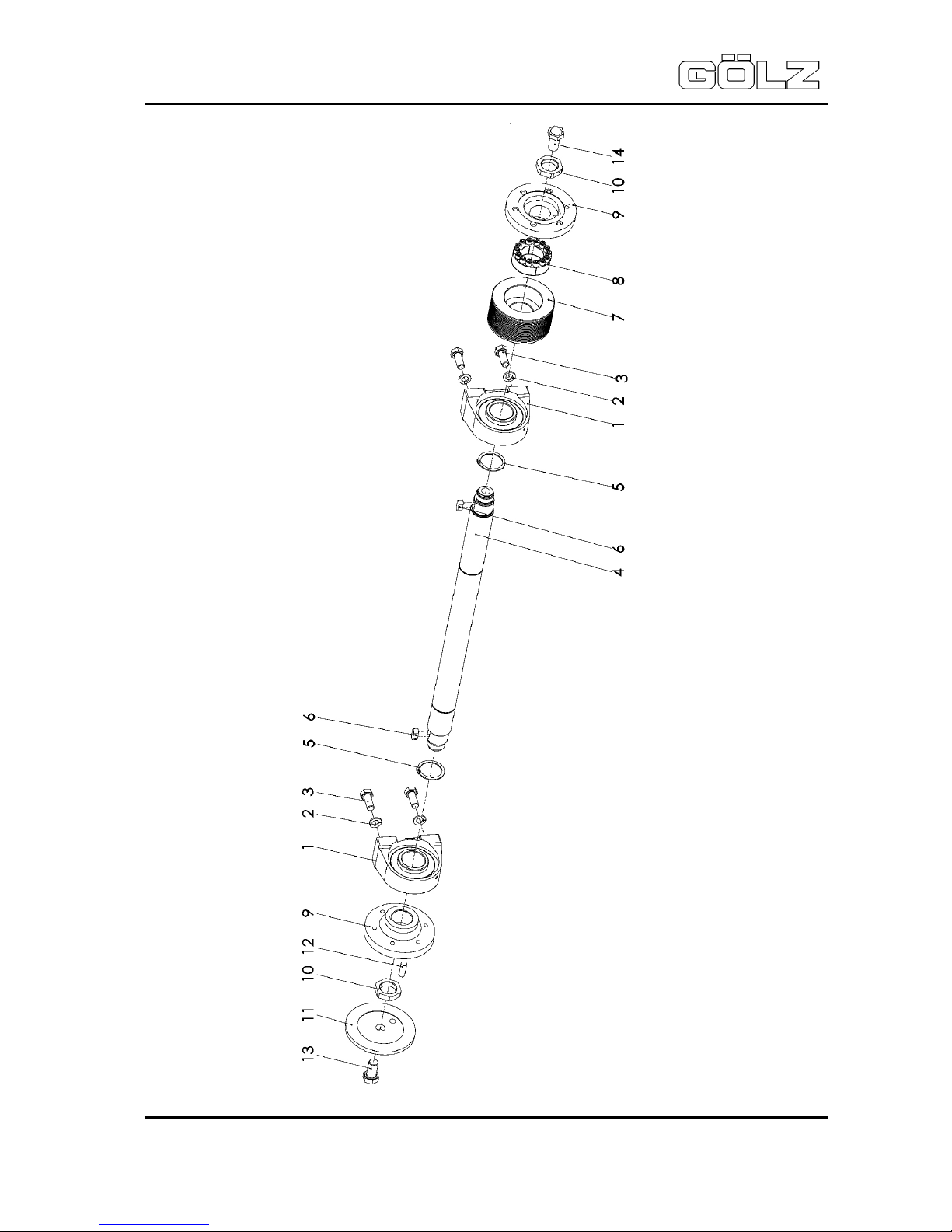
Pos. Artikelnummer Menge Norm Info Benennung Description Désignation
1
0282 241 0072
2
UCPG208 Stehlager Pedestal bearing Chaise palier
2
0286 570 0025
4 DIN 127 A 12 Federring Spring washer Rondelle-ressort
3
0286 570 0020
4
DIN EN
ISO 4017
M 12 x 30 Schraube Screw Vis
4
0282 241 0035
1
Schneidwelle Blade shaft Arbre de coupe
5
9455 621 4330
2 DIN 471 40 x 1,75 Sicherungsring Circlip Circlip
6
0282 520 0032
2 DIN 6885
A 10 x 8 x 22
Paßfeder Key Clavette
7
0282 241 0085
1 110PJ20 Poly-V-Scheibe V-belt pulley
Poulie pour courroie
trapézoidale
0282 241 0037
1
110PK12
Bis Ma.-Nr.
2410005
Poly-V-Scheibe V-belt pulley
Poulie pour courroie
trapézoidale
8
0282 241 0036
1
COM Ø 40 Spannsatz Clamping set Jeu de serrage
9
0282 241 0038
2 Schneidflansch innen Inner flange
Flasque de fixation
intérieure
10
0282 241 0039
2
M 30 x 1,5
Flanschmutter
Flange nut Écrou
11
0282 241 0040
1 Schneidflansch außen Outer flange
Flasque de fixation
extérieure
12
0282 241 0041
1
DIN EN
ISO 2338
10 m6 x 30 Zylinderstift Dowel pin Goupille cylindrique
13
0282 240 0042
1
DIN EN
ISO 8676
M 16 x 1,5
x 30 LH
Schraube Screw Vis
14
0282 240 0040
1
DIN EN
ISO 8676
M 16 x 1,5
X 30
Schraube Screw Vis
Page 35

FS 240 SE
Operating instructions
- 35-
02822410998
5006580-00
Page 36

FS 240 SE
Operating instructions
- 36-
02822410998
5006580-00
Pos. Artikelnummer Menge Norm Info Benennung Description Désignation
1
0281 045 0027
4
DIN EN
ISO 7040
M 6 Mutter Nut Écrou
2
0286 570 0069
8
DIN EN
ISO 7090
B 6,4 Scheibe Washer Rondelle
3
0282 250 0649
2
Ø 20 Befestigungsschelle Mounting clamp Collier de fixation
4
0282 250 0804
4
DIN EN
ISO 4017
M 6 x 60 Schraube Screw Vis
5
0282 252 0148
1
Aufnahme
Richtungsanzeiger
Indicator acceptance
Levé d’indicateur de
direction
6
0282 150 0034
2 DIN 316
M 8 x 20
Schraube Screw Vis
7
0282 252 0107
1
Verlängerung
Richtungsanzeiger
Indicator extension
Rallongement d’indicateur de direction
8
0282 241 0062
1
Richtungspfeil Directional arrow Indicateur de direction
9
0282 250 0777
1
Ø 125 Rad Wheel Roue
10
0295 000 0167
2 DIN 471 12 x 1
Sicherungsring
Circlip Circlip
Page 37

FS 240 SE
Operating instructions
- 37-
02822410998
5006580-00
Pos. Artikelnummer Menge Norm Info Benennung Description Désignation
1
0284 000 0352
1 1/2” I/A Doppelnippel, lösbar
Double nipple,
removeable
Double raccord fileté,
soluble
2
0282 301 0136
2
DIN EN
ISO 7090
B 23 Scheibe Washer Rondelle
3
0282 120 0040
1 R 1/2“ I Minikugelhahn Ball valve
Robinet à tournant
sphérique
4
0282 250 0549
1
1/2“ A GEKA-Kupplung GEKA-coupler GEKA-Accouplement
Page 38

FS 240 SE
Operating instructions
- 38-
02822410998
5006580-00
Pos. Artikelnummer Menge Norm Info Benennung Description Désignation
1
0282 241 0090
2
Schubstange Connecting rod Jambe de force
2
0285 300 0044
2
Kunststoffgriff Handle Poignée
3
0282 241 0095
2
M 10 x 16 Klemmhebel Clamp lever Levier de serrage
Page 39

FS 240 SE
Operating instructions
- 39-
02822410998
5006580-00
Pos. Artikelnummer Menge Norm Info Benennung Description Désignation
1
0282 190 0224
1 DIN 6336 M 8 x 20 Sterngriffschraube Star grip screw Vis de poignée-étoile
2
0282 241 0097
1
Kabelhalter Cable support Cadre support du câble
3
0282 241 0096
1
Zugentlastung Strain relief Décharge de traction
4
0285 300 0027
2
DIN EN
ISO 8752
4 x 32 Spannhülse Clamping sleeve Douille de serrage
5
0298 900 0017
2
DIN EN
ISO 7093
A 17 Scheibe Washer Rondelle
Page 40

FS 240 SE
Operating instructions
- 40-
02822410998
5006580-00
Pos. Artikelnummer Menge Norm Info Benennung Description Désignation
1
0282 241 0045
1 Flanschschutzhaube Flange cover
Carter de protection du
flasque
2
0282 301 0183
1 DIN 11024 Ø 4 Federstecker Spring connector Goupille a ressort
3
0282 241 0034
1 DIN 7337 Ø 4,8 x 10 Blindniet Blind rivet Rivet
4
0282 241 0077
1
0,25 m Knotenkette Knotted link chain Chaîne à nousées
5
0282 241 0049
1
Schutzblech Schneidwelle
Blade shaft protection
Protection d’arbre de
coupe
6
0282 241 0056
1
Rastbolzen Locking pin Boulon d’arrêt
7
0283 300 0278
2
DIN EN
ISO 10642
M 4 x 8 Schraube Screw Vis
8
0295 230 0033
2
DIN EN
ISO 4762
M 6 x 8 Schraube Screw Vis
Page 41

FS 240 SE
Operating instructions
- 41-
02822410998
5006580-00
Page 42

FS 240 SE
Operating instructions
- 42-
02822410998
5006580-00
Pos. Artikelnummer Menge Norm Info Benennung Description Désignation
-
0282 241 0055
1 Pos. 1-23 Schutzhaube kpl. Cover assy.
Carter de protection
compl.
1
0282 241 0048
1 Schutzhaube hinten Cover, back
Carter de protection,
derrière
2
0282 252 0142
1
Scharnier Hinge Charnière
3
0282 241 0052
1 Schutzhaube vorne Cover, front
Carter de protection,
à l'avant
4
0281 045 0027
10
DIN EN
ISO 7040
M 6 Mutter Nut Écrou
5
9008 319 1280
6
DIN EN
ISO 4017
M 6 x 16 Schraube Screw Vis
6
0282 250 0775
2
Griff Handle Poignée
7
0282 250 0084
4
DIN EN
ISO 4762
M 6 x 25 Schraube Screw Vis
8
0282 150 0031
2
R 1/2“ Schlauchtülle Hose clip Embout à olive
9
0282 241 0053
1
Wassergabel Water fork Conduit d’eau
10
0282 240 0039
2
DIN EN
ISO 10642
M 8 x 20 Schraube Screw Vis
11
0295 010 0052
2
2-Ohr-Schelle Clamp Étrier
12
0298 100 0106
1
1 m Schlauch Hose Tuyau
13
0282 301 0183
1 DIN 11024 Ø 4 Federstecker Spring connector Goupille a ressort
14
0282 241 0077
1
0,25 m Knotenkette Knotted link chain Chaîne à nousées
15
0282 241 0034
1 DIN 7337 Ø 4,8 x 10 Blindniet Blind rivet Rivet
16
0295 899 0009
1
Pfeil Aufkleber Label Macaron
17
0295 899 0314
1
Fräswelle Aufkleber Label Macaron
18
0295 899 0346
2
Handver-
letzung
Aufkleber Label Macaron
19
0282 241 0054
2
Gölz Aufkleber Label Macaron
20
0282 241 0049
1
Schutzblech
Schneidwelle
Blade shaft protection
Portection d'arbre de
coupe
21
0282 241 0056
1
Rastbolzen Locking pin Boulon d'arrêt
22
0283 300 0278
2
DIN EN
ISO 10642
M 4 x 8 Schraube Screw Vis
23
0295 230 0033
2
DIN EN
ISO 4762
M 6 x 8 Schraube Screw Vis
Page 43

FS 240 SE
Operating instructions
- 43-
02822410998
5006580-00
Page 44

FS 240 SE
Operating instructions
- 44-
02822410998
5006580-00
Pos. Artikelnummer Menge Norm Info Benennung Description Désignation
-
0282 241 0061
1 Pos. 1-19 Schutzhaube kpl. Cover assy.
Carter de protection
compl.
1
0282 241 0051
1 Schutzhaube Cover Carter de protection
2
0282 250 0775
1
Griff Handle Poignée
3
0282 250 0084
2
DIN EN
ISO 4762
M 6 x 25 Schraube Screw Vis
4
0286 570 0069
2
DIN EN
ISO 7090
B 6,4 Scheibe Washer Rondelle
5
0281 045 0027
2
DIN EN
ISO 7040
M 6 Mutter Nut Écrou
6
0283 900 5002
1
6A-15
1,55 m
Abdichtbürste Seal brush Étanchéité
7
0298 100 0022
24 DIN 7337 Ø 3 x 8 Blindniet Blind rivet Rivet
8
0282 241 0059
2
Wassergabel Water fork Conduit d’eau
9
0282 241 0060
2
Wassergabelaufnahme Water fork support Conduit d'eau levé
10
0282 250 0004
2
DIN EN
ISO 10642
M 8 x 16 Schraube Screw Vis
11
0282 241 0070
2 1/2” I/A Doppelnippel, lösbar
Double nipple,
removeable
Double raccord fileté,
soluble
12
0282 150 0031
2
R 1/2“ Schlauchtülle Hose clip Embout à olive
13
0298 100 0106
1
1 m Schlauch Hose Tuyau
14
0295 010 0052
2
Ø 17-20 2-Ohr-Schelle Clamp Étrier
15
0282 241 0071
1
R 1“ Verschlussstopfen Closing plug Bouchon d'étanchéité
16
0282 241 0054
1
Gölz Aufkleber Label Macaron
17
0282 301 0183
2 DIN 11024 Ø 4 Federstecker Spring connector Goupille a ressort
18
0282 241 0077
2
0,25 m Knotenkette Knotted link chain Chaîne à nousées
19
0282 241 0034
2 DIN 7337 Ø 4,8 x 10 Blindniet Blind rivet Rivet
Page 45

FS 240 SE
Operating instructions
- 45-
02822410998
5006580-00
Pos. Artikelnummer Menge Norm Info Benennung Description Désignation
1
0282 241 0092
1
Gehäuse Box Boîte
2
0282 252 0259
1
Not-Aus-Pilztaster Emergency shut-off Bouton d’arrêt d’urgence
3
0282 252 0261
1
Öffnerkontakt Contact block Bloc en contact
4
0282 650 0148
1 Stern-Dreieck-Schalter Star-Delta connection
Commutateur étoiletriangle
Page 46

FS 240 SE
Operating instructions
- 46-
02822410998
5006580-00
Pos. Artikelnummer Menge Norm Info Benennung Description Désignation
5
0282 650 0147
1
Haupt-Not-Ausschalter Main switch Commutateur principal
6
0282 252 0164
1 180 mm Hutschiene Cap rail Profilé-support
7
0282 252 0164
1 165 mm Hutschiene Cap rail Profilé-support
8
9307 021 0120
4
DIN EN
ISO 7093
A 5,3 Scheibe Washer Rondelle
9
0282 252 0274
1
Sicherungssockel Fuse base Socle de fusible
10
0282 241 0042
3 16A Passeinsatz Neozed
Screw-in sleeve
socket
Vis de calibrage
11
0282 241 0043
3
16A Sicherung Neozed Fuse Fusible
12
0282 241 0082
3
D02 Feder Schraubkappe Spring screw cap Ressort bouchon fileté
13
0282 252 0275
3 32°
Sicherungsschraubkappe
Safety screw cap Bouchon fileté du sécurité
14
0282 252 0268
2 Endstück End cap Bloc d’extrémité
15
0282 301 0212
1
2,5 / 4 mm
34A
Reihenklemme Terminal Bornier
16
0282 241 0111
1 DILM17-10 Schütz Contactor Contacteur
17
0295 510 0990
1
Dichtung Seal Joint
18
0295 510 0640
1
H-B 6 Epic Anbaugehäuse Mounting case Boîte
19
0295 510 0681
1
Rahmen Frame Cadre
20
0267 112 5648
10
DIN EN
ISO 7089
A 4,3 Scheibe Washer Rondelle
21
0295 001 0130
1
DIN EN
ISO 4762
M 4 x 30 Schraube Screw Vis
22
0283 300 0570
2 DIN 6797 A 4,3 Zahnscheibe Lock washer Disque denté
23
9210 260 0600
7
DIN EN
ISO 4032
M 4 Mutter Nut Écrou
24
0298 100 0076
2 DIN 46237
M 4,
1,5-2,5²
Ringkabelschuh Ring terminal Serre-câble
25
0267 112 5646
2 DIN 127 A 4 Federring Spring washer Rondelle-ressort
26
0281 100 0014
3
DIN EN
ISO 4762
M 4 x 20 Schraube Screw Vis
27
0295 510 0051
2
5-polig Modul Buchse Module bushing Module Douille
28
0295 510 0017
9
2,5² Buchsenkontakt Bushing contact Contact de douille
29
0282 241 0075
1
Gölz Aufkleber Label Macaron
30
0267 112 5641
4
DIN EN
ISO 4762
M 6 x 40 Schraube Screw Vis
31
0286 570 0069
4
DIN EN
ISO 7090
B 6,4 Scheibe Washer Rondelle
32
0281 045 0027
4
DIN EN
ISO 7040
M 6 Mutter Nut Écrou
33
0295 000 0129
1
DIN EN
ISO 4762
M 4 x 16 Schraube Screw Vis
34
0282 241 0094
1
16A, CEE Stecker Plug Prise mâle
35
0295 000 0313
4
DIN EN
ISO 4792
M 5 x 25 Schraube Screw Vis
36
0295 000 0170
4
DIN EN
ISO 7089
A 5,3 Scheibe Washer Rondelle
37
0295 000 0177
4
DIN EN
ISO 7040
M 5 Mutter Nut Écrou
38
-
1
Kabel Cable Câble
Page 47

FS 240 SE
Operating instructions
- 47-
02822410998
5006580-00
10. Wiring diagram
 Loading...