

Page 1
FS 240 E
Operating manual
- 1-
02822400988
5006148-01
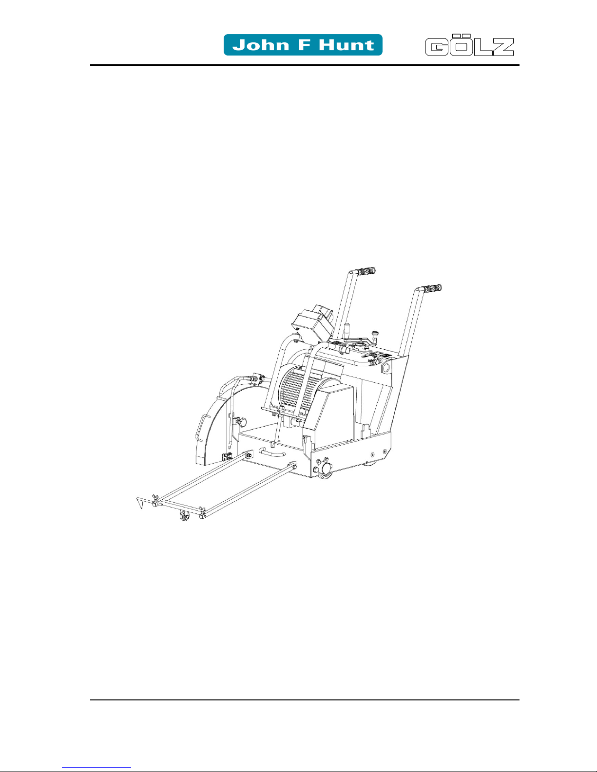
Floor saw
FS 240 E
Art.-Nr. der Bedienungsanleitung 02822400988
ZN der Bedienungsanleitung: 5006148-01
Erstellt am : 10 / 2010
Erstellt von: Mireille Szidat
Datei:
K
:\KDV\5006xxx\5006148-Bedienungsanleitung\
5006148-
01-Bedienungsanleitung-doc.doc
GÖLZ GmbH
Dommer sbach 51
53940 Hellenthal-Blum enthal
Telefon: (02482) 120
Telefax: (02482) 12135
Page 2
FS 240 E
Operating manual
- 2-
02822400988
5006148-01
EG-KONFORMITÄTSERKLÄRUNG
EC-DECLARATION OF CONFORMITY
DECLARATION DE CONFORMITE DE LA CE
Die Fi rma
Manufacturer La Société
GÖLZ GmbH
Dommersbach 51, 53940 Hellenthal - Blumenthal
Tel.: (02482) 120 Fax: (02482) 12135
Erklärt in alleiniger Verantwortung, dass
folgendes Produkt:
FS 240 E
Fugenschneider
Hereby certifies on it’s sole responsibility
that the following product:
FS 240 E
Floor saw
Déclare sous sa seule responsabilité que
le produit suiv ant:
FS 240 E
Scie de sol
Seriennum mer / Seri al number / Numéro de série: _______________________
Auf das sic h diese Erklärung bezieht, mit
folgenden Richtlinien bzw. Normen übereinstimmt:
Maschinenrichtlinie 2006/42/EG
Sicherheits- und Gesundheitsanforderung
EMV-Richtlinie 2004/108/EG
Elektromagnetische Verträglichkeit
Richtlinie 2000/14/EG
Geräuschemission
Europäische Normen
EN 13309:2000
EN 13862:2001
DIN EN ISO 3744
EN 61000
Die oben genannte Firma hält Dokumentationen als Nachweis der Erfüllung
der Sicherheitsziele und die wesentlichen Schutzanforderungen zur Einsicht
bereit.
Which is explicitly referred to by this
Declaration meet the following directives
and standard(s):
Directive 2006/42/EC
Safety and health requirement
Directive 2004/108/EC
Electromagne tic compatibility
Directive 2000/14/EC
Noise emission
European Standard
EN 13309:2000
EN 13862:2001
DIN EN ISO 3744
EN 61000
Documented evidence conforming with
the requirements of the Directive is kept
available for inspection at the above
Manufacturer's, address.
Qui fait l‘objet de la présente déclaration
correspond aux directives et normes
suivantes:
Directive 2006/42/CE
Prescriptions sanitaire et sécurité
Directive 2004/108/CE
Compatibilité électromagnétique
Directive 2000/14/CE
Émission de bruit
Norme européenne
EN 13309:2000
EN 13862:2001
DIN EN ISO 3744
EN 61000
Pour faire foi de la conformité et du respect des règles de sécurité, la documentation peut être consultée au siège
de la Société susmentionnée.
Hellenthal, den 01.10.2010
Page 3

FS 240 E
Operating manual
- 3-
02822400988
5006148-01
Contents
1. Preface.......................................................................................................................... 5
2. General safety references.............................................................................................. 5
2.1 Basic operati on and desi gnated use of the machine ...........................................................6
2.2 Organizational measures....................................................................................................6
2.3 Selection and qualif ication of person...................................................................................7
2.4 Normal operation of t he m achine........................................................................................7
2.5 Special work related to the maintenance and repair of the m ac hine ....................................8
2.6 Information about special risks electrical ener gy .................................................................8
2.7 Gas, dust, steam, smoke....................................................................................................9
2.8 Noise .................................................................................................................................9
2.9 Oils, greases and other chemical substances .....................................................................9
2.10 Changing the loc ation of the machine...............................................................................10
3. Description................................................................................................................... 10
3.1 Main parts........................................................................................................................10
3.2 Technical data..................................................................................................................11
4. Transport and storing................................................................................................... 11
4.1 Transport.........................................................................................................................11
4.2 Storing.............................................................................................................................12
5. Starting ........................................................................................................................ 12
5.1 Before starting..................................................................................................................12
5.2 Packing............................................................................................................................12
5.3 Mounting the diam ond blade ............................................................................................12
5.4 Water supply.................................................................................................................... 13
5.5 Power supply ...................................................................................................................13
6. Operation..................................................................................................................... 13
6.1 Cutting line.......................................................................................................................14
6.2 Starting electric motor.......................................................................................................14
6.3 Setting cutting depth.........................................................................................................14
6.4 Feed................................................................................................................................15
6.5 Finish cutting....................................................................................................................15
6.6 Stopping electric motor.....................................................................................................15
7. Maintenance................................................................................................................ 15
7.1 General............................................................................................................................15
7.2 Lubrication chart...............................................................................................................16
7.3 Electric motor...................................................................................................................16
7.4 V-belts .............................................................................................................................16
Page 4

FS 240 E
Operating manual
- 4-
02822400988
5006148-01
8. Troubleshooting........................................................................................................... 17
9. Wearing parts.............................................................................................................. 19
10. Ersatzteilliste/Spare parts list/Liste des pièces de rechange........................................ 20
11. Wiring diagram............................................................................................................ 31
Page 5

FS 240 E
Operating manual
- 5-
02822400988
5006148-01
1. Preface
Thanks for choosi ng a
GÖLZ
-product. T his operating i nstruction i s designed to fam iliarize the user
with the mac hine and its designated use.
The operating i nstruction cont ains important inform ation on how to operate the machine safely, properly and most ef fi cient ly. Observ i ng these i nstruct ions helps to av oi d danger, to r educe repair c osts
and downtimes and to i nc r ease t he r eliability and life of the machine. The operating instruction is to be
supplemented by t he respective nat ional rules and regulati ons for accident prevention and envir onmental protecti on. The operating instruction must always be avai lable wherever the machine is in use.
This operati ng instruction m ust be read and applied by any person i n charge of work with or on the
machine, such as:
- Operation including setting up, troubleshooting in the course of work, evacuation care and
disposal of fuels and consumables.
- Maintenance (servic ing, inspecti on, repair) and/or
- Transport
In addition to the operating instructions and to the mandatory rules and regulations for accident
prevent ion and env ir onment pr otecti on of the country and place of use of t he machi ne, the gener ally
recognized technical rules for safe and proper working conditions and procedures must also be
observed.
2. General safety references
Jedes Ums etzen de r Masc hine außerh alb des Bereic hs, in dem Sc hneidarbeiten dur chgef ührt wer den, darf nic ht mit rotie rendem Werkzeug durchgeführt werden!
It is not allowed to move the machine with rotating blade outside of the area in which cutting works have to be performed!
Tout dépl aceme nt de la mac hine doit s' opérer sans r otation de l'o util (ris que de bless ures ) ceci est également valable sur le
chantier pour les déplacement entre coupes!
Vor Inbetrieb nahm e Betri ebsa nleit ung lesen!
Read owner’s manual before the first initiation!
Lire la notice avant utilisation!
Wichtiger Hinweis!
Important advice!
Indication importante!
Achtung, spielende Kinder!
Be careful with kids on the work side!
Attention aux enfants!
Staubschutz tragen!
Wear dust protection!
Port de masque!
Achtung, Schneidgefahr!
Danger exist to cut oneself!
Attention danger de coupure!
Nicht berühren!
Never touch!
Ne pas toucher!
Gehörschutz tragen!
Wear ear muffs!
Protection acoustique obligat oire!
Schutzschuhe tragen!
Wear safety boo ts!
Chaussures de sécurite obligatoires!
Achtung, Schneidgefahr!
Danger exist to cut oneself!
Attention danger de coupure!
Schutzhelm tragen!
Wear safety helmet!
Port du casque!
Schutzkleidung tragen!
Wear safety clothes!
Vêtements protecteurs obligatoires!
Warnung vor elektrischer Spannung!
Electrical Hazard!
Attention tension électrique!
Augenschutz tragen!
Wear safety glasses!
Port de lunettes!
Schutzhandschuhe tragen!
Wear protective gloves!
Gants obligatoires!
Warnung vor allgemeiner Gefahr!
General danger!
Attention danger particulier!
Page 6
FS 240 E
Operating manual
- 6-
02822400988
5006148-01
2.1 Basic operation and designated use of the machine
The machi ne has been built in acc ordance with state-of-the- art standards and the recognized safety
rules. Nevertheless, its use may constitute a risk to life and limb of the user or of third parties, or cause
damage to the machine and to ot her material property.
The m achi ne m ust only be used in t echni cal ly perf ect condi t ion i n acc ordance wit h it s designated use
and the i nstructions set out in the operating m anual, and only by saf ety-conscious persons who are
full y aware of the ri sks inv olv ed in operating t he machi ne. Any func tional di sorders, especially those
affecting the safety of t he machine, should therefore be rectified immediately.
Separation bui lding implem ents are exclusiv ely designed for sawing of asphalt, concrete and steel
concrete. Using t he machine for purposes other than t hose mentioned above (such as for) is considered contrary to its designated use. The manufacturer cannot be held liable for any damage
resulting f rom such use. The risk of such misuse lies entirely with the user. Operating the machi ne
within the l im its of it s designated use also inv ol v es observi ng the instr ucti ons set out in the operating
manual and complying with the inspection and maintenance directives.
2.2 Organizational measures
This operating manual must always be at hand at the place of use of the product and must be
accessible to the per son operating the mac hine!
In addition to this operating manual, all other generally applicable legal and other mandatory
regulations relevant to accident prevention and environmental protection must be observed! Such
obligati ons may al so comprise the handling of hazardous material s, provisi oning and/ or wearing of
personal protecti ve equipm ent, or r oad traffi c regul at ions. T hi s operating manual must be supplemented by instructions covering the duties involv ed in supervising and notifying special organizational
features, such as job or ganization, work flows or the person entrusted with the work.
Person entrusted with work on the produc t must have read t he operating manual pri or to taking up
work. Thi s applies especiall y to persons working only occ asionally on t he product, e.g. during set-up
or maintenance activities. Check - at least from time to time - whether the personnel is carrying out the
work in compliance with the operating manual and paying attention to risks and safety-relevant factors.
For reasons of safet y, long hair must be ti ed back or otherwise secured, garments must be closefitting and no jeweller y - including rings - may be worn. S evere injury may result from being caught by
mov ing parts of the m achi ne. Personal prot ecti v e equipm ent m ust be used wherever requi red by the
circum stances or by law (e.g. safety glasses, ear protectors, saf ety boots, suitable saf ety clothing).
Observe the regulations for prevention of accidents! Observe all safety precautions and warnings
attached to t he pr oduc t and always keep them i n good and per fectly legible condition.
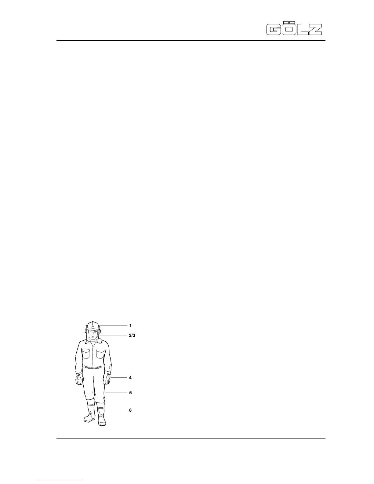
The personal protection equipment should consist of the following parts:
1 Helmet with protection of the ears
2/3 Viso r or safet y glasses / Dust mask
4 Protective gloves
5 Safety clothes
6 Safety boots
Page 7

FS 240 E
Operating manual
- 7-
02822400988
5006148-01
In case event of safety-rel evant modi ficati ons or changes in the behaviour of the product, stop the
product immediat ely and report the malfunc tion to the competent authority/ person.
Do not remove or mak e inoperative any safety devices the pr oduc t is equipped with.
Never make any modifications, additions or conversions which might affect safety without the
manufacturer’s/distributor’s prior approval! This also applies to the installation and adjustment of
safety devices as well as to weldi ng and dr illing work on supporting structur es.
Damaged or worn parts of the product must be r eplaced immediatel y . Use genuine spare parts only.
All spare part s and tools must c ompl y with the t echnical requir ements specif i ed by the manuf actur er/
distributor.
Adhere to the legally prescribed prevent ive maintenance and i nspect ion intervals or those specified in
this operati ng manual!
All m aintenance and repair act ivit ies must be perform ed by qualifi ed personnel using suitable tool s
and other suitabl e workshop equi pment.
Observe the fire alarm and fire fighting measures. The personnel must be made familiar with the
locati on and handling of fire extinguishers!
2.3 Selection and qualification of person
Any work on and with the product must be executed by reli able person only. Statutory minim um age
limits must be observed!
The product must be operated or serviced by trained or properly instructed person onl y . Clearly define
the individual responsibilities of the person for operation, set- up, maintenanc e and r epair.
Make sure that only authorized work on or with t he pr oduc t.
Define t he machine oper ator’s responsibilities -also with regard to observ ing road tr aff ic regulat ions-,
providing the operator with the authority to refuse instructions by third parties that are contrary to
safety.
Do not allow persons to be trai ned or instr ucted or persons taki ng part i n a general tr aining c ourse to
work on or with the product without being perm anently superv ised by an experienced per son.
Work on the electri cal system and equipment of the product must be carried out only by a skilled
electri cian or by proper ly instruct ed persons working under the superv ision and guidance of a skilled
electrician and in accor danc e with electrical engineering rules and regulations.
2.4 Normal operation of the machine
Before begi nning work, f am iliarize yourself with the surroundings and circum stances of the si te, such
as obstacles which might im pede work or traff ic, the soil bearing capacity and the required safety
measures, e.g. barr iers separating the work site from public traffic .
Check the range in gas-, water- and power supply lines bef ore working. Av oid any operational m ode
that might be prejudi c ial to safety!
Take the necessary precaut ions to ensure that the m achine is used only when in a safe and reliabl e
state. Operate the machine only if all protective and safety-oriented devices, such as removable
safety dev ices, emer gency shut-off , sound-proofing el ements and exhausters, are i n place and ful ly
functional.
Each ti m e bef ore y ou start working, check t he product f or obv i ous dam age and def ect s. Any c hanges
(including changes in the performance or behaviour of the product) must be reported to the competent
authority / person imm ediately.
In the event of malfunc tions or changes in the m ac hine’s behaviour , stop the product i mmediately and
secure it against r estarting. Have any defec ts rectif ied immediately !
The machine is designed for use in dayl ight! The m achine operator/ owner must ensure suff icient
workplace li ghting for non-illuminated work sites!
Take precautions to ensure that the operator always has an adequate view of the work. Before leaving
the machine always secure it against inadvert ent movement and unauthorized use!
Page 8

FS 240 E
Operating manual
- 8-
02822400988
5006148-01
During start-up and shut-down procedures always watch the indicators in accordance with the
operating instructions. Before starting up or setting the machine in motion, make sure that nobody is at
risk. Al ways keep at a distance from the edges of building pits and slopes.
2.5 Special work related to the maintenance and repair of the machine
Observe t he adjustment , mai ntenance and inspecti on activ iti es and interv als set out in the operating
manual, including inform ation on the replac ement of par ts or equipment!
These activit ies may be perf ormed by skil led personnel only. Brief the operati ng personnel before
initiating special repair or m aintenance acti vit ies. Appoint a person to supervise such acti vit ies.
In any work concerning the operation, adaptation to production requirements, conversion or
adjustment of the m achine and i t’s safety -orient ed dev ices or any work rel ated to i nspection, mai ntenance and repair, al ways observe the start-up and shut-down procedur es described in the operating
manual as well as the instructions on maintenance activities!
Ensure that the maintenance area i s adequately secured.
The machine is designed for use in dayl ight! The m achine operator/ owner must ensure suff icient
workplace li ghting for non-illuminated work sites!
The fastening of loads and the instructing of crane operators should be entrusted to experienced
persons only. The m ar shaller giving the instructions must be within sight or sound of the operator.
Carry out maint enance and repai r work onl y if the machi ne is positioned on stabl e and lev el ground
and has been secured against inadvertent m ovement and buckling.
If t he machine is compl etely shut down for mai ntenance or repair work, it m ust be secured against
inadvertent restarting.
Clean the machine, especially connections and threaded unions, of any traces of oil, fuel or
preservat ives bef ore carrying out m aintenance or repai r. Never use aggressive detergents. Use lintfree cleaning rags.
Before cleaning the machine with water or other cl eaning agents cover or tape up all openings which for safety and functional reasons- must be protected against the i ngress of water/ steam/ cleaning
agents. After cleaning, r emove all covers and tapes applied for that purpose.
After cleaning, examine the machine for leaks, loose connections, chafe marks or damage. Any
defects found must be rectified without delay.
Always tighten any screwed connections that have been loosened during m aintenance and repair. Any
safety devices rem oved f or set- up, maintenanc e or repair purposes must be refitted and chec k ed
immediately upon c ompleti on of the maintenance and repair work.
2.6 Information about special risks electrical energy
Observe the relevant national regulat ions or standards. Electric al connections must al ways be kept
free f rom di rt and moi sture. Use only ori ginal f uses with the specifi ed rating! Swit ch off the machine
immediately , if t r ouble occurs in the el ec tric power supply!
When working with the machine, mai ntain a safe dist anc e from overhead electric lines. If work is to be
carried out close to overhead lines, the working equipment must be kept well away from them.
Caution, danger! Check out the prescribed safety distances.
If your machine comes into contact with a live wire:
• warn others against approaching and touching the m ac hine
• have t he live wire de-energized
Wor k on the el ect ri cal system or equi pm ent m ay onl y be carr ied out by a skilled electrician himself or
by specially instructed personnel under the control and supervision of such electrician and in
accordance with the applicable engineering rules.
If provided for in the regulations, the power supply to parts of machines and plants, on which
inspection, maintenance and repair work is to be car ried out must be cut of f. Bef ore starting work,
check the de-energi zed part s f or t he presence of power and ground or short-circui t them in addit ion to
insulati ng adjacent li ve parts and elements.
Page 9

FS 240 E
Operating manual
- 9-
02822400988
5006148-01
The electrical equipm ent of machines is to be inspected and checked at regular interv als. Defects
such as loose connections or scorched cables must be rectified immediately.
Necessary work on l ive parts and elements must be carried out only in the presence of a second
person who can cut off the power supply in case of danger by act uating the emergency shut-off or
main power switch. S ecure the working area with a red-and white saf ety chain and a warning sign.
Use insulated tool s onl y .
If mobile electrical equipment, connecting cables and/ or extension/ appliance cords with plug
connectors are used, ensure that such equi pment, c ables and cords are checked for correct functi on
at least once every six months by a qualified electrician or - if sui table testing equipment i s available by a properly instructed person.
Protecti ve instal lations with fault-current protection units used in non-stationary equi pment must be
checked for c or r ec t operation at least once a month by a pr oper ly instructed per son.
Fault-c urrent and f aul t- v ol t age protec ti on uni ts m ust be check ed for correc t operati on by actuati ng the
testing facility:
- once on ev er y working day in the case of mobil e equipment,
- at least once every six months in t he c ase of stationary equipment.
2.7 Gas, dust, steam, smoke
Operate internal combustion engines only on adequately ventilated premises. Before starting the
machine on enc losed premises, make sure that there is suf fici ent ventilation! Danger of life!
Carry out welding, flame-c utting and grinding work on t he machine only of this ahs been expressly
authorized, as ther e may be a risk of explosion and fire.
Before carrying out welding, flame-cutting and grinding operations, clean the machine and its
surroundings from dust and other inflammable substances and make sure that the premises are
adequately ventilated (Risk of explosion). Observe the regulations in force at the respect ive site!
2.8 Noise
Noise Protection devices on the machine must be in the protection position during operation!
Always wear the specified personal hearing prot ec tion (UVV 29 §10)!
2.9 Oils, greases and other chemical substances
When handling hy dr aulic fluids, lubricat ing fluids, greases or preservatives (called operating materials
and lubricant s in the foll owing), the safet y regulations appli cable for t he respectiv e product must be
observed! Avoid prolonged contact of operating mater ials and lubric ants with the skin!
The skin must be c ar efully c leaned of adhering operating m aterials and lubricants!
Exerci se cauti on when handl ing hot operat ing mater ials and l ubricant s, as there is a danger of burns
or scalding. P ar ticularly at liquid temperatures above 60°C, avoid any skin contact with these liquids!
If operat ing m at eri als or l ubri cant s get i nto t he eyes, f l ush thoroughl y wit h dri nki ng water. Then visit a
doctor! Immediately clean up any operating materials and lubricants which have leaked out. Use
absorbent material for this purpose!
Operating m aterials or lubr icants must not be all owed to seep into the soi l or to get into the publi c
sewerage system!
Properly collect, stor e and dispose of operating materials and lubricants which can no longer be used!
Observe and foll ow the respecti ve applic able laws and regulations for handl ing operating mat erials
and lubricants and their disposal in the country in which these substances are used! Obtain
infor mation from the responsible agencies!
Page 10
FS 240 E
Operating manual
- 10-
02822400988
5006148-01
4
5
7
10
2.10 Changing the location of the machine
Use only suitable means of transport and lifting gear of sufficient capacity when loading or transporting
the machine! Appoint an experienced instructor for the lifting operation!
Always observe the i nstruct ions giv en i n the operati ng manual when lif ti ng the machine (use only the
prescribed lifti ng ey es for attachi ng the lifting gear)!
Use only suitable transport vehicles with sufficient load capacity! Secure the load carefully. Use
suitable fastening points for securing!
Before loading the mac hine or part s of it, secure the machi ne/ parts against i nadvert ent mov ement !
Attach a suit able warning sign!
Before using the machine again, make sure that such protection material or devices are properly
removed! P ar ts which had to be removed for t r ansporting of t he machine must be refi tted and secured
carefully befor e the machine is used again!
The recommissioning procedure must be strictly in accor danc e with the operating manual!
Observe the instructions given in the operating manual when reassembling and operating the
machine.
Before sett ing the machine in motion always check that all accessories are safel y stowed.
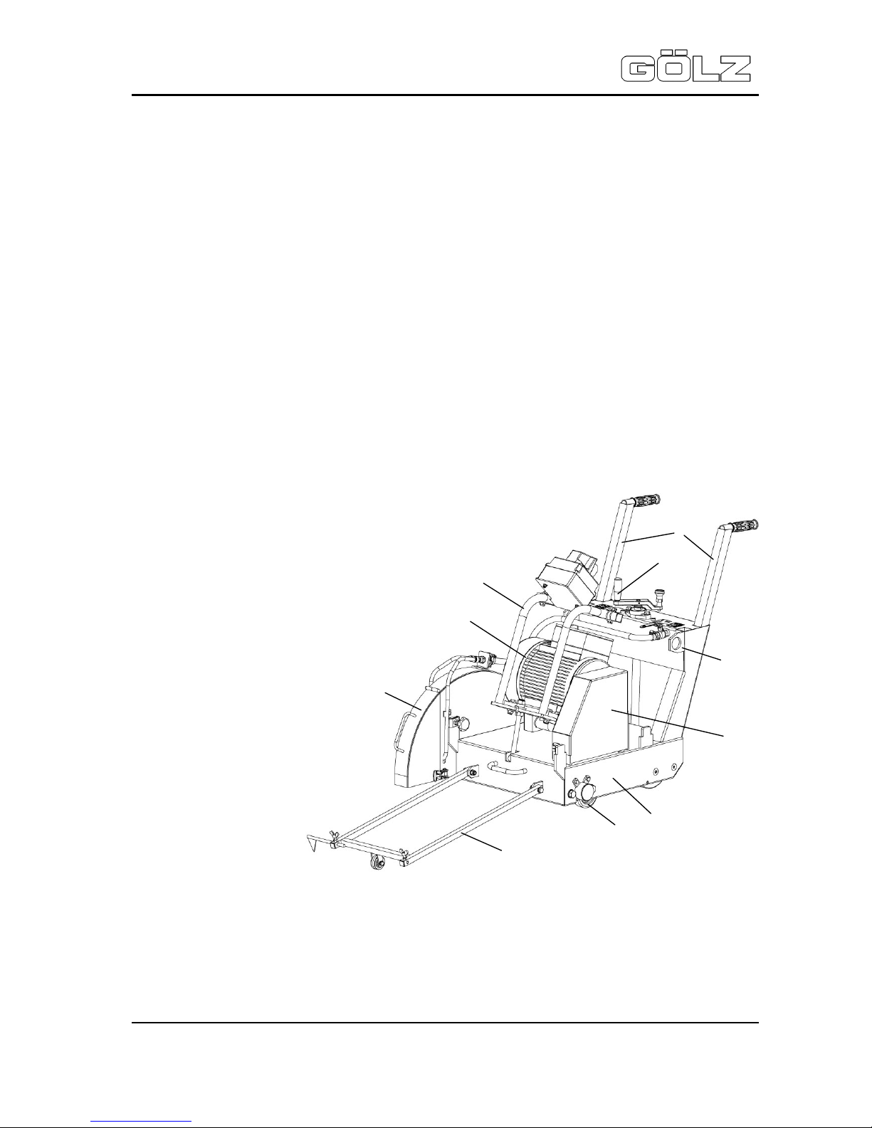
3. Description
3.1 Main parts
1. Frame
2. Undercarriage
3. V-belt guard
4. Eyebolt
5. Crank handle
6. Adjustable push bow
7. Quick change system
8. Electric motor
9. Blade guard
10. Pointer unit
1
3
6
8
9
2
Page 11

FS 240 E
Operating manual
- 11-
02822400988
5006148-01
3.2 Technical data
Engine 3-phase electri c motor, 400V, 50 Hz, 16 A
Power 7,5 kW (10 HP)
Engine speed 1500 rpm
Blade shaft speed 1500 rpm
Max. cutting speed 47 m/s
Max. blade size Ø 600 mm - Ø 23.6 in.
Flange size Ø 120 mm - Ø 4.275 in.
Blade shaft si z e Ø 25,4 mm - Ø 1 in.
Max. cutting depth 240 mm - 9.42 in.
Cutting dept h sel ec tor Crank handle
Feed Manually
Water supply Connection for external water supply
Weight 160 kg - 352.7 lbs.
Dimensions (L x W x H) 840 x 670 x 600 mm - 33 x 26.38 x 23.62 in.
Vibration ISO 5349 VDMA 03/ 2006 a = 3,7 m/s²
Sound power lev el DIN ISO 6393
No load = 100 dB(A)
Full load = 119 dB(A)
Sound pressure lev el DIN EN ISO 6393
No load = 80 dB(A)
Full load = 100 dB(A)
4. Transport and storing
Danger of down coming parts!
Secure boards and machine on the loading area! Do not stand in the danger zone of
the crane !
4.1 Transport
Before t r ansport ing dismount t he blade and lower the mac hine until to the stop.
Use boards for load and unl oading on a truck. Sec ure the machi ne on the loading area.
Fasten a lifting device (tensile strength 1500 kg (3307 lbs.) to the eyebolts (1) when loading and
unloading with an crane. F or singl e transportati on the el ectri c mot or is detachabl e by a qui ck change
system. Open t he locking (2) of the V-belt guard (3) clap it backwards.
Loosen the counter nut W S 24 (4) of the spindl e (5) and screw down the tension nut W S 24 (6) unti l
the V-belt s are det ac hable. Pull out the push bows (7) and push them over the c ar r y ing bow (8).
Page 12

FS 240 E
Operating manual
- 12-
02822400988
5006148-01
1
3
2
6
5
4
7
8
9
Secure with the l inch pins and lower the elect ric motor. Now the locking (9) is f ree and the electri c
motor is detachable. Rem ount in opposite order and check V -belts for correct tension (see chapter
maintenance).
4.2 Storing
Store the machine in a dry, high or locked place, out of the reach of c hildren or unauthor ized persons.
Clean and preserve the machine with corrosion preventive if storing over a longer time like winter time!
5. Starting
5.1 Before starting
Check daily :
• Reliable condition of the machine and blade!
• Well secur ed blade on the blade shaft!
• Well secur ed safety devices like blade guard, V-belt guard and splash guard!
• Report any changes (incl . changes in t he machi ne`s working behav iour ) to the com petent person
immediately . If necessary, stop the machine immediately and loc k it!
5.2 Packing
The m achine i s packed in f oil on a pal let. Remov e t he packing and recycle i t. Use recycli ng containners.
5.3 Mounting the diamond blade
Dismount bl ade guard. Dism ount washer, fl ange screw and outside flange (l ef t hand threaded if blade
is to be mount ed to the right side) . Make sure that the blade shaft, flange screw, flanges and blade are
not damaged and free of sawdust and slurry.
Page 13

FS 240 E
Operating manual
- 13-
02822400988
5006148-01
Washer
„0“ - Position
WS 24
Pay attention to the correct rotation. Direction signs are on the
blade and blade guard. Mount the outside flange and fix it
correctl y with the washer and the flange screw. Mount the blade
guard and secure it with the star grips.
Danger of losing the diamond blade if not correctly
fixed on the blade shaft!
5.4 Water supply
Connect the ext ernal water supply to the GEKA-coupler at the lef t side of t he tending side. The ball
valve should be closed.
5.5 Power supply
Check the electri cal condi tion, input v olt age 400 V/50 Hz. The used power supply m ust comply with
the regulations of power distribution on building sites (fuse protection over FI-protected switch).
Complet ely uncoil extension cables. The starter lever must be in 0 position. Insert in the m ains plug.
6. Operation
Burning hazard touching hot parts (electric motor)!
Dust when using dry cutting blades!
Danger of down coming parts!
The sound pressure level can exceed 85 dB(A)!
Injury hazard of demolitioining parts!
Injury hazard of drawing in clothes by rotating parts!
Page 14

FS 240 E
Operating manual
- 14-
02822400988
5006148-01
Triangl e posi tion
Phase inv er ter
Star position
Crank handle
Stop bolt ac c eptance
Ball valve
Lower
Lift
Stop bolt
Never touch ro t at ing parts like blade, motor or blade shaft and V-belts!
Before starting the machine must be completely lifted. The blade may not have any
ground contact!
6.1 Cutting line
Mark the cutt ing li ne with chalk. Make sure the soil i s clean and align t he blade with the cutting line.
Hinge down the pointer unit and align the directi on si gn wi th the cutti ng line.
6.2 Starting electric motor
Move the starter lever in star position.
Notice correct rotation of the electric motor (sight on the V-belt pulley - rotation left)!
Wr ong rotati on - pull mai ns plug and turn t he phase inv erter with a screw driv er. Repeat starti ng and
move the starter l ever in triangle posit ion after the electric motor has reached maximum speed.
6.3 Setting cutting depth
Open the ball valv e and turn the cr ank handle counter clockwise. Lower the machine to the desired
cutting depth and latch the cr ank handle in one of the two stop-bolt accept anc es.
Page 15

FS 240 E
Operating manual
- 15-
02822400988
5006148-01
Crank handle
Ball valve
Lower
Lift
„0“ - Position
6.4 Feed
Operate with even feed. The el ect ri c m ot or will overstress and the mac hine might r ise out of cut if the
feed is too high. The segments will become dull if the feed is too low.
Operating with too high feed the machine might rise out of cut!
6.5 Finish cutting
Fully lift the fl oor saw and close the ball v alve.
6.6 Stopping electric motor
Move the start lever to the 0 posit ion.
7. Maintenance
Spare parts must com ply wit h the technical requirem ents specified by the manuf acturer. Spare parts
from
GÖLZ
can be relied to do so! Observe the f ollowing indi c ations:
Cut off electric motor and pull mains plug before maintenance, repair or inspection.
Place machin e on stand and secure i t against fall down. Wo rk on the electrical system
or equipment may only be carried out by a skilled electrician!
7.1 General
After cutting clean the machine and check the machine and specially the blade for damages.
Necessary repairs must be car r ied out im mediatel y ( see spare part s l ist).
Page 16

FS 240 E
Operating manual
- 16-
02822400988
5006148-01
7.2 Lubrication chart
Grease the bearings of the blade shaft, cutting depth selector and the undercarriage every 20-30
working hours with heat r esistance fat . Clean periodi call y lose parts lik e pointer uni t and wheels and
grease them with som e drops of oil.
7.3 Electric motor
To prevent over heat clean periodically t he venti lator cowl and the cooling ribs.
7.4 V-belts
Check peri odic all y t he c orrec t t ension of t he V-bel t s. If t he m achi ne i s new or a new set of V-bel t was
mounted check the tension aft er 8 working hours.
Deflexion in the middle approx. 4 mm (0.16" ) - maximum deflexi on force 19 N. Always use a set of Vbelts. Loosen the counter nut (1) WS 24 of the spindle (3) and tense the V-bel ts with the adjusting nut
(2) WS 24 until the cor r ec t tension is reached and fasten the counter nut (1).
Use always a set of V-belts!
1
2
3
Deflexion 4 mm - 0.16 in.
A
A
= min. 1,3 kg - 2.87 lbs.
A = max. 1,9 kg - 4. 18 lbs. with new V-bel t s
A = max. 1,6 kg - 3. 53 lbs. at retensi on
Page 17

FS 240 E
Operating manual
- 17-
02822400988
5006148-01
8. Troubleshooting
Problem Cause Remedy
Electric mot or
Mains plug not connec ted Check conecti on
Fuse of power distribution on
buildi ng si tes has been released
Check fu ses
Electric mot or does not
operate!
Malf unc tion of electrical installation
The electr ical installation
must be checked only by an
electrician
Lowering
Machine does not fully lower!
Undercarriage or threaded spindle
tight
Check undercarri age and
threaded spindel
Cutting
Dull di amond blade
Sharpen or use softer
diamond blade
Machine ri ses out of cut !
Feed to high Reduce feed
Damaged centering of the blade
shaft
Replace blade shaft
War ped blade shaft Replace
Non circular abrasion o f t he
diamond blade!
Loose or damaged blade shaf t
bearings
Tighten or r eplace
No free cut bec ause of siedwards
wear-out of segments
Replace diamond blade
Diamond blade jams in the cut
Damaged diamond blade core Replace diamond blade
Insufficient water flow
Check hoses for f r ac ture free
laying
Wr ong type of diamond blade
Choose different diamond
blade
Feed too high Reduce feed
Abnormal wear-out of
segments
Cutting in loose underground Reduce cutti ng depth
Insufficient water flow
Check hoses for f r ac ture free
laying
Abnormal bl ade wear-out at
sides of co re!
Cutting in loose underground Reduce cutti ng depth
Slippy V - belts Adjust
Bad cutting performance!
Blunt di amond blade
Sharpen or use softer
diamond blade
Page 18

FS 240 E
Operating manual
- 18-
02822400988
5006148-01
Page 19

FS 240 E
Operating manual
- 19-
02822400988
5006148-01
9. Wearing parts
Wearing parts for construction devices mentioned in the operating manual
such as drilling and sawing machines
Wearing parts are the parts subject to operation-related (natural) wear during proper use of the device.
The wearing time cannot be uniformly defined, and differs according to the intensity of use. The
wearing parts must be adjusted, maintained and, if necessary, replaced for the specific device in
accordance with the manufacturer’s operating manual. Operation-related wear is not a reason for
defect c laims.
• Feed and drive elements such as toothed racks, gearwheels, pi nions, spindles, spindl e
nuts, spindle bearings, cables, chains, sprock ets, belts
• Seals, cables, hoses, packings, connectors, c ouplings and switches for pneumatic, hy dr aulic,
water, electr ical and f uel systems
• Guide elements such as guide strips, guide bushes, guide rails, rollers, bearings, sliding
protection supports
• Clam ping element s for quick-separat ing systems
• Flushing head seal s
• Sli de and r oller bearings t hat do not run in an oil bath
• Shaft oil seals and sealing elements
• Fric tion and safety clutches, braking devi c es
• Carbon brushes, commutators/armatures
• Easy-release rings
• Control potentiometers and manual switching elements
• Securing elements such as plugs, anchors, screws and bolts
• Fuses and lamps
• Auxiliary and operating materials
• Bowden cables
• Discs
• Diaphragms
• Spark plugs, glow plugs
• Parts of the reversing starter such as the starting r ope, starting pawl, star ting roll er and
starting spring
• Seali ng br ushes, rubber seal s, spl ash prot ection cloths
• Filters of all kinds
• Drive roll er s, deflection rollers and bandages
• Cable anti-twist elements
• Running and dri ve wheels
• Water pumps
• Cut-material transport rollers
• Drilling, parting and cutting tools
• Energy storage
Wearing parts of this machi ne are grey marked in t he spare parts list .
Page 20

FS 240 E
Operating manual
- 20-
02822400988
5006148-01
10. Ersatzteilliste/Spare parts list/Liste des pièces de rechange
So bekommen Sie schnell und richtig Ihr Ersatzteil
- für Maschine - Modell - Masch.-Nr.
- Artike lnummer - Bezeichnung des Ersatzteiles
- Anzahl der gewünschten Ersatzteile
- Wohin liefern?
- Womit liefern (Post, Eilpost etc.)?
Always indicate:
- machine/model/serial number
- item number and description of the spare part
- amount of spare parts desired
- full address
- goods to be sent by regular mail, express, etc.
Pour obtenir rapidement les pièces de rechange indiquer :
- Nº de la machine, du modèle
- Nº de l’article / description de la pièce désirée
- Nombre de pièces commandées
- Adresse de livraison
- Mode de livraison (poste, express etc...)
Page 21

FS 240 E
Operating manual
- 21-
02822400988
5006148-01
Page 22

FS 240 E
Operating manual
- 22-
02822400988
5006148-01
Pos Artikelnummer Menge Norm Info Benennung Description Désignation
1 0282 240 0103 1 Grundgestell Frame Châssis
2 0282 150 0008 1
UCFL 202
Ø 15
Flanschlager Bearing Flasque bride
3 0286 570 0047 12
DIN EN
ISO 7090
B 10,5 Scheibe Washer Rondelle
4 0295 000 0293 2
DIN EN
ISO 4017
M 10 x 35 Schraube Screw Vis
5 0286 570 0052 6
DIN EN
ISO 7040
M 10 Mutter Nut Écrou
6 0295 600 1043 1
DIN EN
ISO 7090
B 15 Scheibe Washer Rondelle
7 0282 150 0066 1 Handkurbel kpl. Crank handle assy. Manivelle complete
7.1 0295 000 0011 1 Zylindergriff Bolt Poignée
7.2 0282 150 0069 1 Handkurbel Crank handle Manivelle
7.3 0284 650 0064 1 DIN 1481 5 x 24 Spannhülse Clamping sleeve Manchon
7.4 0282 150 0065 1 Rastbolzen Stop bolt Cheville
8 0282 240 0021 2 M 10 Rastbolzenaufnahme Stop bolt acceptance Logement de la cheville
9 0295 000 0216 2 DIN 7349 A 10,5 Scheibe Washer Rondelle
10 0282 240 0071 2 Schubbügel Push bow Poignée
11 0281 045 0028 2 DIN 6336 M 10 x 25 Sterngriffschraube Star grip screw Vis à poignée-étoile
12 0285 300 0044 2 Kunststoffgriff Handle Revêtement poignée
13 0282 065 0011 2
UCFL 205
Ø 25
Lager Bearing Roulement
14 0282 250 0023 8
DIN EN
ISO 7090
B 17 Scheibe Washer Rondelle
15 0286 570 0058 4
DIN EN
ISO 4017
M 16 x 45 Schraube Screw Vis
16 0282 450 0156 4
DIN EN
ISO 7040
M 16 Mutter Nut Écrou
17 0282 240 0027 1 Schneidwelle Blade shaft Arbre de coupe
18 0282 240 0028 2 DIN 6885 A 8 x 7 x 27 Passfeder Key Clavette
19 0282 240 0029 1 DIN 6885 A 8 x 7 x 58 Passfeder Key Clavette
20 0282 240 0016 2 Lagerbock Pedastal Palier
21 0295 000 0179 4
DIN EN
ISO 4017
M 10 x 25 Schraube Screw Vis
22 0282 240 0019 1
3SPA DW90
x Ø 30
Keilriemenscheibe V-belt pulley Poulie à gorge
23 0285 300 0128 1 Gummiriegel kpl. Locking Verrou en caoutchouc
24 0282 240 0030 1
TK85
6 x M 8
Schneidflansch innen Inside flange Flasque intérieure
25 0282 250 0004 6
DIN EN
ISO 10642
M 8 x 16 Schraube Screw Vis
26 0282 150 0055 2
DIN EN
ISO 4017
M 10 x 45 Schraube Screw Vis
27 0282 240 0020 1
Ø 40 x Ø 17
x 3
Scheibe Washer Rondelle
28 0282 240 0044 1
DIN EN
ISO 8676
M 16 x 1,5
x 50 LH
Schraube Screw Vis
29 0282 240 0041 1
DIN EN
ISO 8676
M 16 x 1,5
x 50
Schraube Screw Vis
30 0282 240 0024 1
Schutzhaube Schneid-
welle
Blade shaft guard
Capot de protection du
disque de coupe
31 0282 250 0005 2
DIN EN
ISO 4017
M 8 x 16 Schraube Screw Vis
Page 23

FS 240 E
Operating manual
- 23-
02822400988
5006148-01
Page 24

FS 240 E
Operating manual
- 24-
02822400988
5006148-01
Pos Artikelnummer Menge Norm Info Benennung Description Désignation
32 0282 240 0026 1 Schneidflansch aussen Outside flange Flasque extérieur
33 0282 240 0008 1 Richtungsanzeiger Pointer unit Tiges de guidage
34 0282 120 0045 2
20 x 20 x
1,5-2
Stopfen Plug Capuchon
35 0282 150 0026 1 Ø 50 x Ø 8 Rad Wheel Roue
36 0282 250 0006 2
DIN EN
ISO 7090
B 8,4 Scheibe Washer Rondelle
37 0281 045 0091 1
DIN EN
ISO 4014
M 8 x 45 Schraube Screw Vis
38 0282 065 0005 1
DIN EN
ISO 7040
M 8 Mutter Nut Écrou
39 0282 150 0034 2 DIN 316 M 8 x 20 Schraube Screw Vis
40 0282 150 0022 1 Richtungspfeil Pointer arrow Flechè de direction
41 0282 150 0047 1 1/2" I Kugelhahn Ball valve Robinet
42 0282 150 0031 1
R 1/2" A
X Ø 13
Schlauchtülle Nozzle Embout à olive
43 0282 170 0032 1 G 1/2" I Geka-Kupplung Geka-Coupler Geka-Raccord
44 0282 170 0031 1 Ø 13 Schlauchtülle Nozzle Embout à olive
45 0282 240 0002 1
Ø 13,2 x
Ø 3,3 x 1000
Schlauch Hose Tuyau
46 0282 250 0112 2 Ø 16 - Ø 25 Schlauchschelle Clip Collier
o.A. 0295 899 0051 1 Typenschild Type plate Plaque d’identification
o.A. 0295 899 0033 1 „Pikto“ Aufkleber Label Macaron
o.A. 0295 899 0042 1 „Auf - Ab“ Aufkleber Label Macaron
o.A. 0295 899 0227 1 LWA Aufkleber Label Macaron
Zubhör für B ündigschnitt - Ac c essory – Ac c esoi r e
Pos Artikelnummer Menge Norm Info Benennung Description Désignation
o.A. 0282 240 0040 1
DIN EN
ISO 8676
M 16 x 1,5
x 30 LH
Schraube Screw Vis
o.A. 0282 240 0042 1
DIN EN
ISO 8676
M 16 x 1,5
x 30
Schraube Screw Vis
Page 25

FS 240 E
Operating manual
- 25-
02822400988
5006148-01
Page 26

FS 240 E
Operating manual
- 26-
02822400988
5006148-01
Pos Artikelnummer Menge Norm Info Benennung Description Désignation
1 0282 240 0022 2
UCFL 204
Ø 20
Flanschlager Bearing Flasque bride
2 0282 520 0118 4
DIN EN
ISO 10642
M 12 x 45 Schraube Screw Vis
3 0282 250 0105 6
DIN EN
ISO 7090
B 13 Scheibe Washer Rondelle
4 0285 300 0015 6
DIN EN
ISO 7040
M 12 Mutter Nut Écrou
5 0282 150 0009 1 Gewindespindel Spindle Axe fileté
6 0282 240 0052 1 Spindelmutter Spindle nut Arbre récepteur
7 0282 240 0014 1 Fahrwerk Undercarriage Châssis
8 0282 140 0002 2
Ø 160 x 60
x Ø 20
Rad Wheel Roue
9 0282 065 0003 2
Ø 100 x 35
X Ø 12
Rad Wheel Roue
10 0282 240 0064 1
DIN EN
ISO 2341
Form B Bol zen Bolt Goujon
11 0282 250 0023 1
DIN EN
ISO 7090
B 17 Scheibe Washer Rondelle
12 0284 650 0046 1
DIN EN
ISO 1234
4 x 25 Splint Split pin Goupille
13 0282 065 0006 1
DIN EN
ISO 4017
M 16 x 60 Schraube Screw Vis
14 0281 045 0051 1
DIN EN
ISO 4032
M 16 Mutter Nut Écrou
Page 27

FS 240 E
Operating manual
- 27-
02822400988
5006148-01
Page 28

FS 240 E
Operating manual
- 28-
02822400988
5006148-01
Pos Artikelnummer Menge Norm Info Benennung Description Désignation
1 0282 240 0005 1 Motoraufnahme hinten Rear mounting plate
Réception arrière du
moteur
2 0282 900 0101 1 Motor Motor Moteur
3 0282 240 0006 1 Motoraufnahme Front mounting pla te Réception moteur
4 0295 000 0216 6 DIN 7349 A 10,5 Scheibe Washer Rondelle
5 0286 570 0052 2
DIN EN
ISO 7040
M 10 Mutter Nut Écrou
6 0282 150 0055 2
DIN EN
ISO 417
M 10 x 45 Schraube Screw Vis
7 0282 250 0023 2
DIN EN
ISO 7090
B 17 Scheibe Washer Rondelle
8 0282 240 0061 2 Ausgleichsbuchse Bushing Douille
9 0282 240 0060 1 Motorverstellspindel Spindle
Ace taraudé de positionnement du moteur
10 0281 045 0051 2
DIN EN
ISO 4032
M 16 Mutter Nut Écrou
11 0282 450 0156 1
DIN EN
ISO 7040
M 16 Mutter Nut Écrou
12 0295 000 0173 2
DIN EN
ISO 4017
M 10 x 30 Schraube Screw Vis
13 0282 300 0116 1
DIN EN
ISO 4017
M 16 x 70 Schraube Screw Vis
14 0285 300 0985 1 DIN 6885
A 10 x 8 x 70
Passfeder Key Clavette
15 0282 240 0018 1
3SPA DW90
x Ø 38
Keilriemenscheibe V-belt pulley Poulie à gorge
16 0282 240 0072 1
XPA-975
LW
Keilriemen Sa tz V-belt set Jeu de Courroie s
17 0282 240 0989 1 Motorschalter Starter
Boîte de comma nde du
moteur
18 0286 570 0069 4
DIN EN
ISO 7090
B 6,4 Scheibe Washer Rondelle
19 0295 000 0084 2
DIN EN
ISO 4762
M 6 x 20 Schraube Screw Vis
20 0281 045 0027 2
DIN EN
ISO 7040
M 6 Mutter Nut Écrou
21 0295 000 0003 2 8 x 45 Rohrklappenstecker Linch pin Goupille articulée
o.A. 0298 100 0061 1 PG16 Mutter Nut Écrou
o.A. 0298 100 0066 1 PG16 7353 Verschraubung Connection Raccord
o.A. 0298 100 0067 1
167MS
/21/16
Reduzierung Reduction Réducteur
o.A. 0298 100 0065 1 PG16 7363 Verschraubung Connection Raccord
o.A. 0282 130 0054 1 Distanzring Distance plate Entretoise
o.A. 0298 100 0207 1 Kabel Cable Câble
Page 29

FS 240 E
Operating manual
- 29-
02822400988
5006148-01
Page 30

FS 240 E
Operating manual
- 30-
02822400988
5006148-01
Pos Artikelnummer Menge Norm Info Benennung Description Désignation
- 0282 240 0100 1 Pos. 1-16 Schutzhaube kpl. Blade guard assy.
Capot de protection
complete
1 0282 240 0104 1 Schutzhaube Blade guard Capot de protection
2 0285 300 0090 1
DIN EN
ISO 7090
B 21 Scheibe Washer Rondelle
3 0282 170 0032 1 1/2" Geka-Kupplung Geka-Coupler Geka-Raccord
4 0282 240 0102 1 Y 1/2" Steckverschraubung Connectin Raccord
5 0285 300 0128 2 Gummiriegel kpl. Locking Verrou en caoutchouc
6 0282 240 0066 1 Spritzlappen Splash guard Bavette
7 0282 250 0006 4
DIN EN
ISO 7090
B 8,4 Scheibe Washer Rondelle
8 0282 150 0035 2
DIN EN
ISO 4017
M 8 x 20 Schraube Screw Vis
9 0282 065 0005 2
DIN EN
ISO 7040
M 8 Mutter Nut Écrou
10 0282 240 0101 2 Ø 12 Schelle Clip Collier
11 0286 570 0069 2
DIN EN
ISO 7090
B 6,4 Scheibe Washer Rondelle
12 0295 000 3530 2
DIN EN
ISO 4017
M 6 x 15 Schraube Screw Vis
13 0282 240 0105 1 6 x 3 x 600 Schlauch Hose Tuyau
14 0282 240 0105 1 6 x 3 x 600 Schlauch Hose Tuyau
15 0281 045 0028 2 DIN 6336 M 10 x 25 Sterngriffschraube Star grip screw Vis à poignée-étoile
16 0295 899 0055 1 „FS240“ Aufkleber Label Macaron
Pos Artikelnummer Menge Norm Info Benennung Description Désignation
o.A. 0295 000 2100 1 Werkzeugtasche Tool bag Trousse à outils
o.A. 0295 000 2012 1 DIN 911 SW 5 Inbusschlüssel All en key Clé
o.A. 0295 000 2011 1 DIN 911 SW 6 Inbusschlüssel All en key Clé
o.A. 0295 000 2036 1 DIN 984 SW 13 Maulschlüssel Wrench Clé platte
o.A. 0295 000 2052 1 DIN 984 SW 24 Maulschlüssel Wrench Clé platte
o.A. 0295 000 2038 1 DIN 984 SW 17 Maulschlüssel Wrench Clé platte
Page 31

FS 240 E
Operating manual
- 31-
02822400988
5006148-01
11. Wiring diagram
Strip terminal (motor)
Switch box
Plug
 Loading...