

Page 1

FS175
Translation of the original operating instruction and spare parts list
- 1-
5007287-00
BA-E
®
Floor saw
FS 175
ZN der Bedienungsanleitung: 5007287-00
Erstellt am: 03 / 2014
Erstellt von: Sabrina Linden
Datei: K:\KDV\5007xxx\5007287-Bedienungsanleitung\
5007287-00-Bedienungsanleitung-E.doc
GÖLZ® GmbH
Dommersbach 51
D-53940 Hellenthal
Telefon: +49 (0) 2482 12 200 / Telefax: +49 (0) 2482 12 222
E-Mail: info@goelz.de / Internet: www.goelz.de
Page 2

FS175
Translation of the original operating instruction and spare parts list
- 2-
5007287-00
BA-E
®
Page 3

FS175
Translation of the original operating instruction and spare parts list
- 3-
5007287-00
BA-E
®
All rights reserved according to DIN ISO 16016.
No part of this document (instruction manual and spare parts list) may be reproduced, adapted, transmitted,
transcribed, stored on a data medium or be translated into another language without prior written approval of
GÖLZ
®
GmbH
Dommersbach 51
D-53940 Hellenthal
Guarantee
We reserve the right to amend any information included in this document (manual instruction and spare parts
list) at any time and without prior notice.
GÖLZ
®
assumes no warranty for these documents.
GÖLZ
®
shall not be liable for errors in this document (manual instruction and spare parts list) or for any
collateral or consequential damage in connection with shipment, performance or use of the material.
Page 4

FS175
Translation of the original operating instruction and spare parts list
- 4-
5007287-00
BA-E
®
EC-DECLARATION OF CONFORMITY
Manufacturer
GÖLZ® GmbH
Dommersbach 51, D-53940 Hellenthal
Tel.: +49 (0) 2482 12 200 / Fax: +49 (0) 2482 12 222
Declare hereby certifies on its sole responsibility that the following product:
FS 175
Floor saw
Serial number:____________________
which is explicitly referred to by this declaration meet the following directives:
2006/42/EC Safety and health requirement
2004/108/EC Electromagnetic compatibility
97/68/EG i.d.F. 2002/88/EC Exhaust emission directive
2000/14/EC Noise emission
meet the follwing standards:
EN 12100-1 / EN 12100-2 , EN 13862:2001, EN 13309:2000, EN 61000, DIN EN ISO 3744-1995
Documented evidence conforming to the requirements of the directives is kept available for inspection at the
above manufacturer’s address.
Hellenthal, den 13.03.2014 ………………………………………
General Manager
B. Schmitz
Page 5

FS175
Translation of the original operating instruction and spare parts list
- 5-
5007287-00
BA-E
®
Contents
Preface ................................................................................................................................ 7
Warning signs and symbols ............................................................................................. 7
1. Machine description ................................................................................................... 8
1.1 Intended use-description ................................................................................................. 8
1.2 Technical data ................................................................................................................. 8
1.3 Shipment and provided accessory ................................................................................... 9
1.4 Main parts........................................................................................................................ 9
1.5 Safety devices ............................................................................................................... 10
2. Basic safety instructions ......................................................................................... 11
2.1 Intended use .................................................................................................................. 11
2.2 Operating range ............................................................................................................ 11
2.3 Organisational measures ............................................................................................... 11
2.4 Selection and qualification of person ............................................................................. 13
2.5 Safety instructions governing specific operational phases ............................................. 13
2.6 Special work related to the maintenance and repair of the machine .............................. 14
2.7 Information about special risks with electrical energy .................................................... 14
2.8 Gas, dust, steam, smoke ............................................................................................... 15
2.9 Noise ............................................................................................................................. 15
2.10 Illumination .................................................................................................................... 15
2.11 Oils, greases and other chemical substances ................................................................ 16
2.12 Transport ....................................................................................................................... 16
2.13 Store .............................................................................................................................. 17
3. Preparing for Operation ........................................................................................... 18
3.1 Export checking ............................................................................................................. 18
3.2 Installation ..................................................................................................................... 18
3.3 Blade ............................................................................................................................. 18
3.3.1 Mounting the blade ..................................................................................................................... 19
3.4 Water supply ................................................................................................................. 19
4. Operation ................................................................................................................... 21
4.1 Before starting the machine ........................................................................................... 21
4.2 Starting the machine ...................................................................................................... 22
4.3 Cutting operation ........................................................................................................... 22
4.4 Stop cutting operation .................................................................................................... 23
4.5 Changing the blade ....................................................................................................... 23
5.
Maintenance .............................................................................................................. 24
5.1 General ......................................................................................................................... 24
Page 6

FS175
Translation of the original operating instruction and spare parts list
- 6-
5007287-00
BA-E
®
5.2 Lubricating chart ............................................................................................................ 24
5.3 Poly-V belt ..................................................................................................................... 24
5.4 Machine ......................................................................................................................... 25
5.5 Blade ............................................................................................................................. 25
6. Taper bushes installation instructions ................................................................... 26
6.1 To assemble .................................................................................................................. 26
6.2 Removal ........................................................................................................................ 26
7.
Troubleshooting ....................................................................................................... 27
8. Spare parts list .......................................................................................................... 28
8.1 Using the spare parts list ............................................................................................... 28
8.1.1 Safety regulation ......................................................................................................................... 28
8.1.2 Ordering information ................................................................................................................... 28
8.1.3 Distribution agencies ................................................................................................................... 29
8.2 Wearing parts ................................................................................................................ 30
9. Exploded view and spare parts list ......................................................................... 31
9.1 Undercarriage ................................................................................................................ 31
9.2 Push bow ...................................................................................................................... 33
9.3 Shaft .............................................................................................................................. 37
9.4 Shaft support ................................................................................................................. 39
9.5 Water tank 30L .............................................................................................................. 40
9.6 Blade guard / Water supply ........................................................................................... 41
9.6.1 Blade guard ................................................................................................................................. 43
9.7 Engine ........................................................................................................................... 45
9.8 Pointer unit .................................................................................................................... 49
Page 7

FS175
Translation of the original operating instruction and spare parts list
- 7-
5007287-00
BA-E
®
Preface
Thanks for choosing a
GÖLZ®-product. This operating instruction is designed to familiarize the user with
the machine and its designated use.
The operating instruction contains important information on how to operate the machine safely, properly and
most efficiently. Observing these instructions helps to avoid danger, to reduce repair costs and downtimes
and to increase the reliability and life of the machine. The operating instruction is to be supplemented by the
respective national rules and regulations for accident prevention and environmental protection. The
operating instruction must always be available wherever the machine is in use. This operating instruction
must be read and applied by any person in charge of work with or on the machine, such as:
• Operation including setting up, troubleshooting in the course of work, evacuation care and disposal of
fuels and consumables.
• Maintenance (servicing, inspection, repair) and/or
• Transport
In addition to the operating instructions and to the mandatory rules and regulations for accident prevention
and environment protection of the country and place of use of the machine, the generally recognized
technical rules for safe and proper working conditions and procedures must also be observed.
In dieser vorliegenden Bedienungsanleitung sind alle für den bestimmungsgemäßen Einsatz notwendigen
Informationen enthalten. Sollten dennoch spezielle Fragen auftauchen, so wenden Sie sich bitte
an ihre Vertretung, an einen unserer Außendienstmitarbeiter oder direkt an uns:
GÖLZ® GmbH
Dommersbach 51, D-53940 Hellenthal
Telefon: +49 (0) 2482 12 200 / Telefax: +49 (0) 2482 12 222
E-Mail: info@goelz.de / Internet: www.goelz.de
Warning signs and symbols
Wear safety boots!
Wear safety glasses! Wear ear muffs!
Wear hard hat!
Wear safety clothes!
Wear dust protection!
Wear protective
gloves!
Read owner’s manual
before first initiation!
Important advice!
Never touch!
General danger!
Danger exists
to cut oneself!
It is not allowed to move the machine with rotating blade outside of the area in which
cutting works have to be performed!
Page 8

FS175
Translation of the original operating instruction and spare parts list
- 8-
5007287-00
BA-E
®
1. Machine description
1.1 Intended use-description
The FS 175 is a floor saw with a cutting depth of up to 165 mm.
Its operating range includes the concrete and asphalt road construction, but mainly for transverse,
longitudinal and expansion joints.
Operate the machine only using tools in accordance with the manufacturer’s instruction. Using other tools is
considered contrary to its designated use. The manufacturer cannot be held liable for any damage resulting
from such use. The risk of such misuse lies entirely with the user. Der FS 175 is equipped with a petrol
engine Honda GX390 and should be operated with the fuel specified by the manufacturer.
1.2 Technical data
Max. cutting depth 165 mm - 6.5 in.
Max. blade-Ø 450 mm - 17.7 in.
Flange size Ø 100 mm - 3.9 in.
Blade shaft size Ø 25,4 mm - 1 in.
Engine
Gasoline engine HONDA GX390
8,7kW (11,8 PS)
Max. cutting speed with blade 63,5 m/s
Engine shaft speed 3600 min-1
Blade shaft speed 2691 min-1
Feed manual
Excavation Manual with foot pedal
Cutting depth control Scale on frame
Water supply
30l Water tank, for dry cutting blades
Connection for external water supply wet cutting
diamond blades
Poly-V-belt tension manual
Dimensions (L x W x H) approx. 588 x 910 x 1009 mm - 23.1 x 35.8 x 39.7 in.
Weight (without water tank and blade) approx. 86 kg - 189.6 lbs.
Sound power level after DIN ISO 6393
No load = 104 dB(A)
Full load = 114 dB(A)
Sound pressure level after DIN ISO 6393
No load =88 dB(A)
Full load =98 dB(A)
Vibration ISO 5349 VDMA 03/2006 a = 4,5 m/s²
Information: Unconditional observe the owner’s manual of the engine manufacturer,
which is added!
Page 9

FS175
Translation of the original operating instruction and spare parts list
- 9-
5007287-00
BA-E
®
1.3 Shipment and provided accessory
• Floor saw FS175 without blade
• Wrench SW 17, SW 30 and SW 32
• Operating instruction and spare parts list floor saw
• Operating instruction engine
For the item number of accessories, please refer to the current catalogue of GÖLZ®
If accessories are used which do not correspond to GÖLZ® specifications, no liability is assumed for any
damage resulting hereof.
For details regarding the selection of the right GÖLZ® diamond blades, please refer to the current GÖLZ
®
catalogue for diamond tools.
1.4 Main parts
The base frame (1) is the basis for the floor saw. All other components are built on the base frame.
The floor saw FS 175 is equipped with a petrol engine of Honda (2). For any other information, please refer
to the attached operating manual of the engine manufacturer.
The height adjustable push bar (3) allows a non-fatiguing working.
In order to allow dust formation during cutting respectively cooling of the cutter blade, the floor saw is
equipped with a pluggable water tank (4).There is also the possibility to cool directly by means of the water
supply network respectively to bind the dust.
1. Frame
2. Engine
3. Push bow
4. Water tank 30l
5. Blade guard
6. Cutting depth indicator
7. Poly-V belt guard
8. Pointer unit
9. Hand wheel
4
1
3
9
5
8
7
2
6
Page 10
FS175
Translation of the original operating instruction and spare parts list
- 10-
5007287-00
BA-E
®
The cutting disc guard (5) provides the operator and the persons in his working area with optimum protection
during the cutting process.
By means of the convenient cutting depth setting (6), the operator can read, at any time, the cutting depth.
The rib drive is protected by a protective hood (7). Thus, the risk of injury is reduced by the rib drive.
Furthermore, the rib drive is also protected from impurity during the cutting process.
The route indicator (8) allows precise cuts.
Thanks to the direction indicator the operator can monitor and respect the cutting direction.
Der Aushub des Sägeblattes erfolgt beim FS175 über ein Handrad (9) welches mit einer Trapezspindel
verbunden ist.
The digging of the blade is using by a hand wheel (9) which is connected with a trapezoidal spindle.
1.5 Safety devices
Danger: During cutting or displacing the machine, all safety devices shown below must
be mounted!
Blade guard
Poly-V belt guard
Page 11

FS175
Translation of the original operating instruction and spare parts list
- 11-
5007287-00
BA-E
®
Note / Important: Contains important information which stands out from the other text!
2. Basic safety instructions
In this manual the following terms and symbols are used for particular important information:
Important text passages are highlighted in italics or bold or can be found in a grey highlighted text field.
2.1 Intended use
The machine has been built in accordance with state-of-the-art standards and the recognized safety rules.
Nevertheless, its use may constitute a risk to life and limb of the user or of third parties, or cause damage to
the machine and to other material property.
The machine must only be used in technical perfect condition in accordance with its designated use and the
instructions set out in the operating manual, and only by safety-conscious persons who are fully aware of the
risks involved in operating the machine. Any functional disorders, especially those affecting the safety of the
machine, should therefore be rectified immediately!
The machine is designed exclusively for cutting in concrete, reinforced concrete, natural stone, cast stone
and brickwork. Using the machine for purposes other than mentioned above (such as cutting in wood and so
on) is considered contrary to its designated use. The GÖLZ® GmbH cannot be held liable for any damage
resulting from such use. The risk of such misuse lies entirely with the user.
Only use gear drives and motors, which are provided by GÖLZ® GmbH. Also attend those operating
manuals.
Operating the machine within the limits of its designated use also involves observing the instructions set out
in the operating manual and complying with the inspection and maintenance directives
2.2 Operating range
Do not modify, add components to or retrofit the unit in a way which could affect its safety and do not use
non-official accessories! This is not allowed without prior approval of GÖLZ® GmbH!
2.3 Organisational measures
This operating manual must always be at hand at the place of use of the machine and must be accessible to
the person operating the machine!
In addition to this operating manual, all other generally applicable legal and other mandatory regulations
relevant to accident prevention and environmental protection must be observed! Such obligations may also
comprise the handling of hazardous materials, provisioning and/ or wearing of personal protective
equipment, or road traffic regulations.
Attention: Read and observe all the operating instructions which belong to this unit!
Attention: Contains instructions which must be strictly observed to prevent damage from
the unit and the operator!
Page 12
FS175
Translation of the original operating instruction and spare parts list
- 12-
5007287-00
BA-E
®
This operating manual must be supplemented by instructions covering the duties involved in supervising and
notifying special organizational features, such as job organization, work flows or the person entrusted with
the work. Person entrusted with work on the machine must have read the operating manual prior to taking up
work. This applies especially to persons working only occasionally on the machine, e.g. during set-up or
maintenance activities.
Check - at least from time to time - whether the personnel is carrying out the work in compliance with the
operating manual and paying attention to risks and safety-relevant factors.
For reasons of safety, long hair must be tied back or otherwise secured, garments must be close-fitting and
no jewellery - including rings - may be worn.
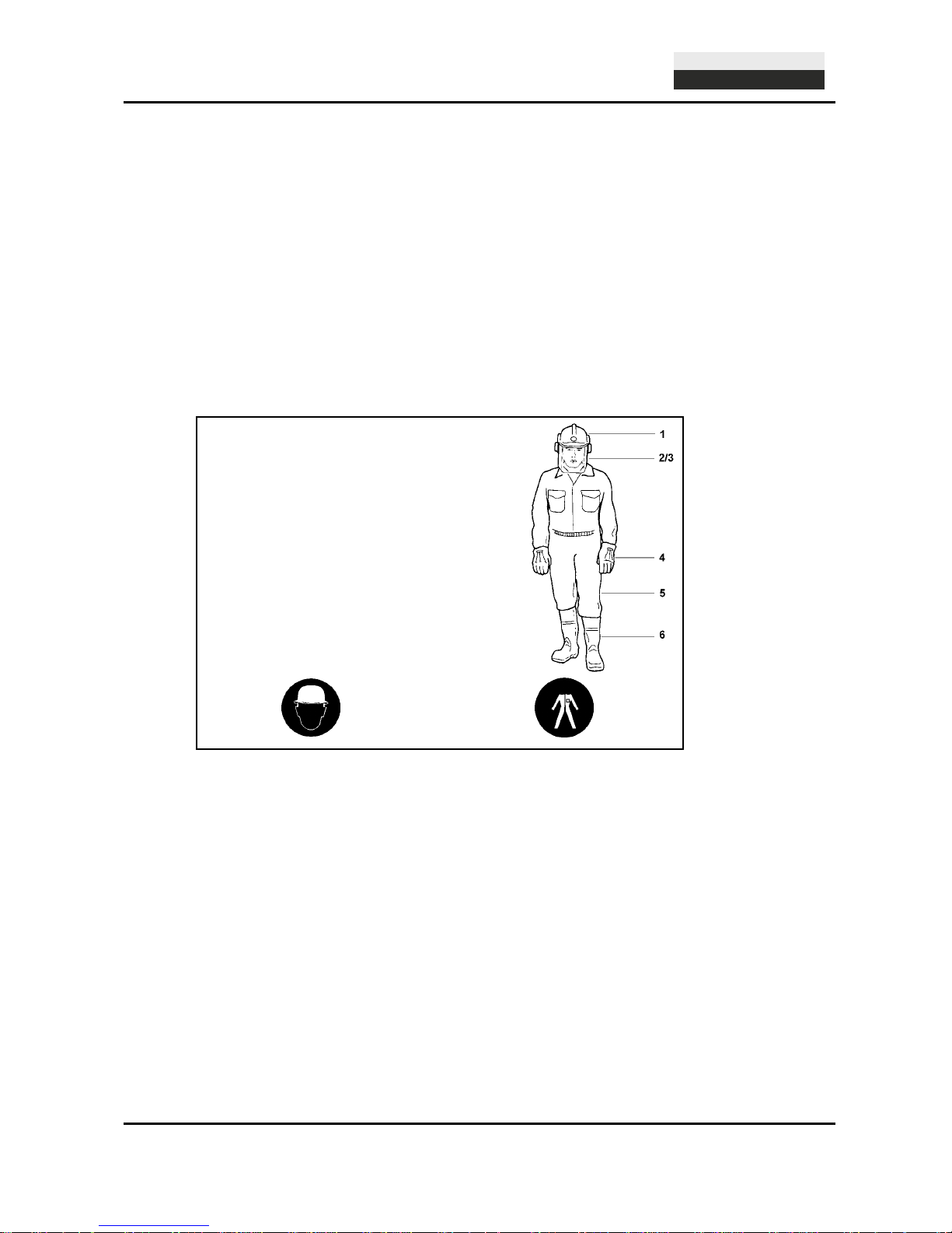
Severe injury may result from being caught by moving parts of the machine. Personal protective equipment
must be used wherever required by the circumstances or by law (e.g. safety glasses, ear protectors, safety
boots, suitable safety clothing). Observe the regulations for prevention of accidents! Observe all safety
precautions and warnings attached to the machine and always keep them in good and perfectly legible
condition.
The personal protection equipment should consist of the following parts:
In case event of safety-relevant modifications or changes in the behaviour of the machine, stop the machine
immediately and report the malfunction to the competent authority/ person. Do not remove or make
inoperative any safety devices the machine is equipped with.
Never make any modifications, additions or conversions which might affect safety without GÖLZ® GmbH
prior approval! This also applies to the installation and adjustment of safety devices as well as to welding and
cutting work on supporting structures.
Damaged or worn parts of the product must be replaced immediately. Use genuine spare parts only.
All spare parts and tools must comply with the technical requirements specified by the manufacturer/
distributor. Adhere to the legally prescribed preventive maintenance and inspection intervals or those
specified in this operating manual!
Hydraulic hose pipes must be changed within the specified or appropriate intervals, even if no safetyrelevant defects are visible.
All maintenance and repair activities must be performed by qualified personnel using suitable tools and other
suitable workshop equipment. Observe the fire alarm and fire fighting measures. The personnel must be
made familiar with the location and handling of fire extinguishers!
1) Helmet with protection of the ears
2) Visior or safety glasses
3) Dust mask
4) Protective gloves
5) Safety clothes
6) Safety boots
Page 13

FS175
Translation of the original operating instruction and spare parts list
- 13-
5007287-00
BA-E
®
Important: Wet cutting is to be accomplished while working! This prevents the appearance of particulate matter and increases the life-time of the diamond tool!
2.4 Selection and qualification of person
Only permitted personnel is allowed to work on and with the machine! The legal minimum age is to be
observed!
Only assign trained and instructed personnel! Clearly define the responsibilites of the personnel with regard
to operating, setting-up, maintaining and repairing the machine! The GÖLZ® GmbH can assist you in training
your personnel.
Make sure that only instructed and competent personnel works on the machine. Define the responsibility of
the machine operator, also in terms of traffic regulations and enable him to refuse instructions of third parties
which breach safety regulations.
Personnel that is to be trained or to be instructed or that is serving a general training is only to be permitted
to operate the machine under the supervision of an experienced person.
To operate the machine you must be rested, in good physical condition and mental health. If you have any
condition that might be aggravated by strenuous work, check with your doctor before operating with the
machine. Do not operate the machine if you are under the influence of any substance (drugs, alcohol) which
might impair vision, dexterity or judgment.
Works on electrical, pneumatic, combustion and hydraulic fittings and equipment are only to be carried out
by qualified personnel or instructed people being directed and supervised by qualified personnel in
compliance with the respective rules!
2.5 Safety instructions governing specific operational phases
Before work
Avoid any operational mode that might be prejudicial to safety!
Before beginning work, familiarize yourself with the surroundings and circumstances of the site, such as
obstacles in the working and travelling area, the soil bearing capacity and any barriers separating the
construction site from public roads.
Take the necessary precautions to ensure that the machine is used only when in a safe and reliable state.
Operate the machine only if all protective and safety-oriented devices, such as removable safety devices,
emergency shut-off equipment, sound-proofing elements and exhausters, are in place and fully functional.
Regard all safety specifications!
Check the machine at least once per working shift fo
r obvious damage and defects. Report any changes
(incl. changes in the machine’s working behaviour) to the competent organization/ person immediately. If
necessary, stop the machine immediately and lock it. Have any defects rectified immediately. At any time,
ensure the operator has sufficient view to his working area, in order to have intervention to the working
process.
Wet cutting is to be accomplished while working. This prevents the appearance of particulate matter and
increases the life-time of the diamond tool. During start-up and shut-down procedures always watch the
indicators in accordance with the operating instructions!
Before starting or setting the machine in motion, make sure that nobody is at risk. Keep children and
unauthorized persons away from the work area.
Noise protection equipment on the unit must be in protective position during operation. Wear the required
individual ear protection!
Always keep at a distance from the edges of building pits and slopes. Avoid any operation that might be a
risk to machine stability! Keep the work area clean. Cluttered areas and benches invite injuries! Do not
operate when you are tired! Watch what you are doing! Risk of stumbling! Cables and hoses must complete
rolling up. After assembly do not leave any tools, a wrench for example, on the unit.
Check to see that the tools are removed from the machine before operating! Damaged blades have to be
changed immediately. Use only recommended blades from the GÖLZ® GmbH.
Control the working area for water-, gas- and electrical lines!
Page 14

FS175
Translation of the original operating instruction and spare parts list
- 14-
5007287-00
BA-E
®
During work
Make sure, that the machine is well fastened before and while cutting!
Never touch rotating parts like blade shaft or blade!
After work
Before leaving the machine always secure it against unauthorized use!
2.6 Special work related to the maintenance and repair of the machine
Observe the adjustment, maintenance and inspection activities and intervals set out in the operating
instructions, including information on the replacement of parts and equipment! These activities may be
executed by skilled personnel only.
Brief operating personnel before beginning special operations or maintenance work, and appoint a person to
supervise the activities.
In any work concerning the operation, conversion or adjustment of the machine and it’s safety-oriented
devices or any work related to maintenance, inspection and repair, always observe the start-up and shutdown procedures described in the operating instructions and the information on maintenance work. Ensure
that the maintenance area is adequately secured.
Carry out maintenance and repair work only of the machine is positioned on stable and level ground and has
been secured against inadvertent movement and buckling. If the machine is completely shut down for
maintenance and repair work, it must be secured against inadvertent starting.
To avoid the risk of accidents, individual parts and large assemblies being moved for replacement purposes
should be carefully attached to lifting tackle and secured. Use only suitable and technically perfect lifting gear
and suspension systems with adequate lifting capacity. Never work or stand under suspended loads.
The fastening of loads and the instructing of crane operators should be entrusted to experienced persons
only. The marshaller giving the instructions must be within sight or sound of the operator.
For carrying out overhead assembly work always use specially designed or otherwise safety-oriented ladders
and working platforms. Never use machine parts as a climbing aid. Wear safety harness when carrying out
maintenance work at greater heights.
Clean the machine, especially connections and threaded unions, of any traces of oil, fuel or preservatives
before carrying out maintenance / repair. Never use aggressive detergents. Use lint-free cleaning rags.
Before cleaning the machine with water, steam jet or detergents, cover or tape up all openings which -for
safety and functional reasons - must be protected against water, steam or detergent penetration.
Do not clean the machine with a high-pressure cleaner. The hard water jet can put damage to parts of the
machine. After cleaning, remove all covers and tapes applied for that purpose.
After cleaning check the machine for loose connections, chafe marks and damage! Have identified defects
repaired immediately!
Always tighten any screwed connections that have been loosened during maintenance and repair.
Any safety devices removed for set-up, maintenance or repair purposes must be refitted and checked
immediately upon completion of the maintenance and repair work. Ensure that all consumables and replaced
parts are disposed of safely and with minimum environmental impact.
2.7 Information about special risks with electrical energy
Observe the relevant national regulations or standards. Electrical connections must always be kept free from
dirt and moisture.
Use only original fuses with the specified rating! Switch off the machine immediately, if trouble occurs in the
electric power supply!
If your machine comes into contact with a live wire:
• warn others against approaching and touching the machine
• have the live wire de-energized
Page 15

FS175
Translation of the original operating instruction and spare parts list
- 15-
5007287-00
BA-E
®
When working with the machine, maintain a safe distance from overhead electric lines. If work is to be
carried out close to overhead lines, the working equipment must be kept well away from them. Caution,
danger to life!
• Check out the prescribed safety distances.
• Work on the electrical system or equipment may only be carried out by a skilled electrician himself or by
specially instructed personnel under the control and supervision of such electrician and in accordance
with the applicable engineering rules.
• If provided for in the regulations, the power supply to parts of machines and plants, on which inspection,
maintenance and repair work is to be carried out must be cut off.
• Before starting work, check the de-energized parts for the presence of power and ground or short-circuit
them in addition to insulating adjacent live parts and elements.
The electrical equipment of machines is to be inspected and checked at regular intervals. Defects such as
loose connections or scorched cables must be rectified immediately.
Necessary work on live parts and elements must be carried out only in the presence of a second person who
can cut off the power supply in case of danger by actuating the emergency shut-off or main power switch.
Secure the working area with a red-and white safety chain and a warning sign. Use insulated tools only.
If mobile electrical equipment, connecting cables and/ or extension/ appliance cords with plug connectors are
used, ensure that such equipment, cables and cords are checked for correct function at least once every six
months by a qualified electrician or - if suitable testing equipment is available - by a properly instructed
person.
Protective installations with fault-current protection units used in non-stationary equipment must be checked
for correct operation at least once a month by a properly instructed person.
Fault-current and fault-voltage protection units must be checked for correct operation by actuating the testing
facility:
• once on every working day in the case of mobile equipment,
• at least once every six months in the case of stationary equipment.
2.8 Gas, dust, steam, smoke
Operate combustion engines only in well-ventilated rooms! Before starting the unit in closed rooms, make
sure that the room is sufficiently ventilated and use the exhaust gas hose!
Welding, burning and grinding operations on the machine are only to be carried out if this is explicitly
authorized (there is the danger of fire and explosion)!
Before welding, burning and grinding operations clean the machine and its surrounding area from dust and
flammable substances and care for sufficient ventilation (danger of explosion)!
When working in confined spaces observe any existing national regulations!
2.9 Noise
During operation sound protection devices on the machine must be in safe position. Wear the prescribed
personal ear protection! (UVV 29 § 10, Article 29 of the Accident Prevention regulations).
The use of noise emitting machines may be restricted to certain times by national or local regulations.
2.10 Illumination
The machine is designed for use in daylight! The machine operator / owner must ensure sufficient workplace
lighting for non-illuminated work sites!
Page 16

FS175
Translation of the original operating instruction and spare parts list
- 16-
5007287-00
BA-E
®
Attention: Check that all parts of the machine are
well fastened before transporting. Before
transporting the blade must be removed!
For loading, only use lifting gear and tackle of
sufficient capacity. Lift the machine using the
lifting eye.
2.11 Oils, greases and other chemical substances
When handling hydraulic fluids, lubricants, greases or preservatives (referred to hereinafter as fuels and
lubricants), the safety regulations which apply to the respective machine are to be observed!
Avoid long contact of the fuels and lubricants with your skin! Careful cleaning of the skin from adhering fuels
and lubricants is necessary.
Be careful when handling hot consumables (risk of burning or scalding) particularly at liquid temperatures
above 60°C, avoid any skin contact with these liquids!
If you get fuels or lubricants in your eyes, rinse them immediately and carefully with potable water. Then
consult a doctor.
Remove flown out fuels and lubricants immediately! Therefore use a binder.
Fuels and lubricants must not seep into the soil or into the public sewage system! Fuels and lubricants which
can no longer be used are to be collected, properly stored and to be properly disposed of.
The respective regulations and laws for handling fuels and lubricants which are valid in the country of use
are to be observed and adhered to. This also applies to the disposal of such fuels and lubricants. To inform
yourself turn to the responsible authorities.
2.12 Transport
Use only suitable means of transport and lifting gear of sufficient capacity when loading or transporting the
machine! Appoint an experienced instructor for the lifting operation!
Always observe the instructions given in the operating manual when lifting the machine (use only the
prescribed lifting eyes for attaching the lifting gear)!
Use only suitable transport vehicles with sufficient load capacity! Secure the load carefully. Use suitable
fastening points for securing!
Before loading the machine or parts of it, secure the machine against inadvertent movement! Attach a
suitable warning sign!
The blade must be removed for transport. Even in case of a minor change of location, the engine must be
stopped!
Before using the machine again, make sure that such protection material or devices are properly removed!
Parts which had to be removed for transporting of the machine must be refitted and secured carefully before
the machine is used again!
Before setting the machine in motion always check that all accessories are safely stowed.
The recommissioning procedure must be strictly in accordance with the operating instruction! Observe the
instructions given in the operating instruction when reassembling and operating the machine.
During cuts displace the machine only with non-rotating blade (not running engine)!
Lifting eye
Page 17

FS175
Translation of the original operating instruction and spare parts list
- 17-
5007287-00
BA-E
®
Injury hazard: Down coming parts!
Attention: Store blades just standing or hanging!
2.13 Store
Store the machine in a dry, high or locked place, out of the reach of children or unauthorized persons. Clean
and preserve the machine with corrosion preventive if storing over a longer time like winter time!
Note: Store dismounted blades so, that the blades not exposed to mechanical damages and harmful
environmental conditions (UV radiation, temperature, humidity, etc.).
Page 18

FS175
Translation of the original operating instruction and spare parts list
- 18-
5007287-00
BA-E
®
Attention: Read and observe all operating instructions which are relevant for the
machine (floor saw, engine ...)!
Attention: Before starting up, check the engine oil level and fill up the fuel!
3. Preparing for Operation
3.1 Export checking
Remove the transport packaging and dispose of it in an environmentally responsible way. Check the
machine for completeness and intactness. For the scope of delivery, see "Scope of delivery and provided
accessory"
Secure the machine against accidental start-up and rolling away.
The machine is supplied with engine oil but without fuel.
3.2 Installation
Place the machine on an even, firm and stable ground. Have the working area well lightened. Keep the
working area clean, cluttered areas invite injuries. Operating the machine on enclosed premises, make sure
that there is sufficient ventilation. Observe the regulations in force at the respective site.
3.3 Blade
The cutting discs must meet the specification of GÖLZ® GmbH. Use the corresponding cutting discs
depending on the material to be processed, the machining process and the type of work to be performed!
When not used properly, no liability is assumed for damages resulting therefrom.
All used cutting discs must be designed, regarding their maximum admissible cutting speed, for the max.
drive speed of the machine. For machines with variable drive speed, use cutting discs which, regarding their
maximum admissible cutting speed, correspond to the respective maximum drive speed of the machine.
Never use faulty or damaged blades. Check the correct rotation of the blade to the spindle shaft!
Check the blade is well fastened before beginning to operate. Defective cutting discs must be replaced
immediately!
Cut off the engine or disconnect the power supply before mounting or changing blade. After mounting, do not
leave any tools, such as open-end spanners, on the machine.
Use only blades suitable to the blade acceptance (arbor hole, flanges).
Note: If the oil level is too low, fill up the engine according to the operating manual of the
engine manufacturer! Fill up the fuel for the engine according to the operating manual of
the engine manufacturer!
Danger: Faulty or damaged blades can cause injuries to the operator and other persons!
Page 19

FS175
Translation of the original operating instruction and spare parts list
- 19-
5007287-00
BA-E
®
Information: Wrong rotation of the blade will result in more wear of the blade!
Information: Clean all fastening devices of the blade (flanges, thread of the blade shaft,
screws and nuts) before mounting the blade!
Important: The operation is to be carried out in wet cutting, in order to prevent the
occurrence of harmful particulate matter and to increase the lifetime of the cutting tool.
3.3.1 Mounting the blade
Blade mounting:
• Mount the blade to the manufacturer’s odds (Observe the min. flange-Ø; use only original screws or
nuts).
• Use only blade diameters which are allowed by the manufacturer.
Remove the cutting disc guard and unscrew the outer clamping
flange SW 32, left-hand thread.
All clamping surfaces must be clean and undamaged.
Fit the cutting disc. Pay attention to the correct direction of
rotation!
Observe the direction of rotation arrows on the cutting disc and
the cutting disc guard.
Mount the outer clamping flange again, fit the cutting disc
guard and secure it with the screw.
3.4 Water supply
Danger: Wrong rotation of the blade may result in segments cracking off and can cause
injuries to the operator or other persons!
SW32
Danger: It is not allowed to operate the machine without cutting disc blade guard!
Attention: Tools which are only designed for wet cutting technique, must never be used
without water supply! Always make sure that there is enough water supply!
Page 20

FS175
Translation of the original operating instruction and spare parts list
- 20-
5007287-00
BA-E
®
The supply of water at the cut ensures that the tool is cooled, the dust of the material is bound and the cut is
rinsed out.
Cutting with wet-cutting blades:
Connect the water supply to the GEKA-coupler (1) of the machine. Check the ball valve (2) is closed (ball
valve lever in 90°-position to the water flow).
For cutting open the ball valve (2) (ball valve lever in the water flow position).
Cutting with dry-cutting blades:
Fill the water tank with clean water. Connect the GEKA-coupler of the water tank to the GEKA-coupler of the
machine. Check the ball valve is closed (ball valve lever in 90°-position to the water flow).
For cutting open the ball valve (ball valve lever in the water flow position) and the valve of the water tank (3).
3
2
Attention: Use only water for cutting which is free from coarse impurities! Do not use salt
water!
Danger: Do not use the attached water tank when cutting with wet cutting diamond
blades. The segments may crack off and cause injuries to the operator or bystanders!
Page 21

FS175
Translation of the original operating instruction and spare parts list
- 21-
5007287-00
BA-E
®
Information: Unconditional observe the owner’s manual of the engine manufacturer!
Danger: Never touch rotating parts like blade shaft or blade while operating!
4. Operation
4.1 Before starting the machine
Check the machine for safe operating condition.
• All components must be properly mounted.
• The functions of the combustion engine must function properly.
• Do not make any changes on operating elements and safety devices.
The machine may only be operated in safe operating condition.
Lock the push bars so that the machine can be operated in a favorable posture.
If work is carried out where harmful or explosive substances, such as dust, sludge occur, observe the
applicable national regulations.
If there is a risk that, during the cutting process, material particles are accelerated outwards, wear safety
goggles.
When travelling on public roads, ways and places always observe the valid traffic regulations and, if
necessary, make sure beforehand that the machine is in a condition compatible with these regulations.
After operating secure the machine against unintentional moving.
Appropriate to the application of the machine it could be necessary to wear further protective equipment.
The working area is reserved only for the operator. Keep unauthorized persons out of the working area.
Make sure the operator always has well sight to the working area. He always has to intervene in the working
process. Never operate the machine without mounted safety devices.
Danger: Demolition parts can cause injuries to the operator while cutting!
Danger: Down coming parts at the building site can cause injuries to the operator!
Danger: The sound pressure may exceed 85 dB(A)!
Page 22

FS175
Translation of the original operating instruction and spare parts list
- 22-
5007287-00
BA-E
®
Danger: As soon as the combustion engine is started, the cutting shaft, respectively the
cutting disc, starts rotating too!
Careless handling can lead to life-threatening injuries caused by the rotating cutting disc. Only operate the
machine with fully mounted blade guard.
Nobody is allowed to remain in the working area nor in the area where falling segments of the cutting disc
can be accelerated outwards (minimum safety distance 10m). If this safety distance cannot be respected, the
danger zone must be closed or be marked by warning signs.
Care for the whereabouts of cooling and rinsing water as well as of cutting sludge.
Cutting sludge must be collected, filtered and disposed of.
4.2 Starting the machine
Completely rise the machine (blade may have no ground contact). Start the engine as described in the
engines manual.
4.3 Cutting operation
Connect the water supply and slowly lower the machine with the hand wheel (1) till the blade has ground
contact. Putting down the machine to the desired cutting depth which is displaying on the cutting depth
indicator (2).
Before you lower the machine by means of the hand wheel (1), the mini ball valve is to be opened. Lower the
machine to such extent that you reach the desired cutting depth (2).
Pull then the indexing plunger (3) on the control panel, so that it snaps into the catch disk in order to fix the
desired cutting depth.
Work with even feed pressure. Too high feed pressure leads to overload of the engine, there is a risk that the
machine raises. Too low feed pressure polishes the segments and they become blunt.
During cuts displace the machine only with non-rotating blade (not running engine)!
Danger: Operating with too high feed the machine might rise out of cut! In emergency
situations cut off the engine as described in the engines manual!
1
2 3
Page 23

FS175
Translation of the original operating instruction and spare parts list
- 23-
5007287-00
BA-E
®
Note: Do not lower the cutting disc forcibly, this could lead to damage to the cutting disc
and to the machine.
In order to produce a clean cutting line, do not carry out the entire cutting depth in one
cutting process.
4.4 Stop cutting operation
After cutting completely raise the machine and cut off the engine as described in the engines manual.
4.5 Changing the blade
The blade must be changed if:
• the diamond segments of the blade are completely worn
• the material to be cut changes
• the blade turns irregularly
• the diamond segments are damaged or broken
For fitting a new blade, proceed as described in the chapter "Mounting the blade".
Attention: In order to avoid damage to the machine and the cutting disc, please observe
the maximum cutting depth!
Danger: Some parts of the combustion engine become very hot during operation, risk of
burns!
Page 24

FS175
Translation of the original operating instruction and spare parts list
- 24-
5007287-00
BA-E
®
Attention: When handling oil, grease and other chemical substances, observe the
product-related safety regulations!
Information: Clean the machine after every operation. Observe local environmental regulations!
5. Maintenance
5.1 General
For maintenance jobs the machine has to be shut down. For maintenance jobs which must be done while the
machine is running, the blade has to be dismounted before beginning the job.
In accordance to the given cycles, the subsequently described maintenance work has to be enforced. Also
the wearing part subject to no certain maintenance-intervals has to be checked regularly for wear and to
adjust if necessary or to exchange. With I.C. engines, the maintenance work has to be enforced in
accordance with the separate maintenance-instruction of the engine manufacturer.
Before
starting
work
After
work
Weekly Yearly
In the event of
a malfunction
If
damaged
Complete machine
Visual inspection
(condition, absence of
leaks)
X X X
clean X
Flange and blade holder clean X
Poly-V belt
check X X X X
replace X
Water nozzle and
feeding hoses
clean X
Tools
check X X
clean X
replace X
5.2 Lubricating chart
Grease the blade shaft bearings after 20 working hours with heat resistance fat. From time to time clean the
foot pedal, pointer unit and wheels and grease them with some drops of oil.
5.3 Poly-V belt
Unscrew the screws that fix the motor (4x M10x30, DIN EN ISO 4017) and the screw that fixes the eccentric.
Move the motor forwards by turning the eccentric counter clockwise. In this position the poly-V belt can be
replaced easily.
Stress the poly-V belt by turning eccentric clockwise. To fix the motor, screw down the M10x30 screws.
Information: Unconditional observe the owner’s manual of the engine manufacturer,
which is added!
Page 25

FS175
Translation of the original operating instruction and spare parts list
- 25-
5007287-00
BA-E
®
5.4 Machine
Clean the machine after each duty and check all functions. Replace all necessary parts that are out of order
or worn out immediately.
5.5 Blade
When ending a cutting job - check blade as follows:
Check segments for cracks or break-outs, Cracks between segment and core barrel, Deformation
and out of round wear.
In case of doubt, send the blade for repair.
Page 26

FS175
Translation of the original operating instruction and spare parts list
- 26-
5007287-00
BA-E
®
6. Taper bushes installation instructions
6.1 To assemble
Clean and de-grease the bore and taper surfaces of the bush and the tapered bore of the pulley. Insert the
bush in the pulley hub and line up the holes (half thread holes must line up with half straight holes).
Lightly oil the grub screws or the cap screws and screw them in, do not tighten yet.
Clean and de-grease the shaft. Fit pulley with taper bush on shaft and locate in desired position.
When using a key it should first be fitted in the shaft Keyway. There should be a top clearance between the
key and the keyway in the bore.
Using a hexagon socket wrench gradually tighten the grub/cap screws in accordance with the torques as
listed in the schedule of screw tightening torques. When the drive has been operating under load for a short
period (half to one hour) check and ensure that the screws remain at the appropriate tightening torque. In
order to eliminate the ingress of dirt fill all empty holes with grease.
6.2 Removal
Slacken all screws. Depending on the size of the bush remove one or two. After oiling point and thread of
grub screws or under head and thread of cap screws, insert them into the jacking off holie(s) in bush.
Tighten screw (s) uniformly and alter neatly until the bush is loose in the hub and pulley is free on the shaft.
Remove pulley bush assembly from shaft.
Bush Screw tightening torques (Nm)
Screw
Quantity Size
1008
1108
5.6 2
1/4“
BSW
1310
1315
20 2
3/8“
BSW
1210
1215
20 2
3/8“
BSW
1610
1615
20 2
3/8“
BSW
2012 31 2
7/16“
BSW
2517 48 2
1/2“
BSW
3020
3030
90 2
5/8“
BSW
3535 112 3
1/2“
BSW
4040 170 3
5/8“
BSW
4545 192 3
3/4“
BSW
5050 271 3
7/8“
BSW
Page 27

FS175
Translation of the original operating instruction and spare parts list
- 27-
5007287-00
BA-E
®
7. Troubleshooting
Problem Cause Remedy
Engine
Engine does not start!
Fuel tank empty Fill up
Dirty fuel lines Clean
Bad engine performance!
Dirty air cleaner Clean
Lowering
Machine lowers
without
actuating the foot pedal!
Faulty gas pressure spring Replace
Machine does not fully lower!
Undercarriage or gas pressure
spring tight
Check undercarriage and gas
pressure spring
Cutting
Machine rises
out of cut!
Dull diamond blade
Sharpen or use softer diamond
blade
Faulty gas pressure spring Replace
Feed too high Reduce feed
Non circular abrasion
of the diamond blade!
Damaged centring of the blade
shaft
Replace blade shaft
Warped blade shaft Replace
Loose or damaged blade shaft
bearings
Tighten or replace
Diamond blade jams
in the cut!
No free cut because of sidewards
wear-out of segments
Replace diamond blade
Damaged diamond blade core Replace diamond blade
Abnormal wear-out of
segments!
Insufficient water flow Check hoses for fracture free laying
Wrong type of diamond blade Choose different diamond blade
Feed too high Reduce feed
Cutting in loose underground Reduce cutting depth
Abnormal blade wear out at
sides of core!
Insufficient water flow Check hoses for fracture free laying
Cutting in loose underground Reduce cutting depth
Bad cutting performance!
Slippy V-belts Adjust
Blunt diamond blade
Sharpen or use softer diamond
blade
Attention: In the event of changes in the behaviour of the machine during operation, stop
the machine immediately and report the malfunction to the competent authority/person!
Note: For more fault finding refer the operating instruction of the engine
manufacturer which is enclosed!
Page 28

FS175
Translation of the original operating instruction and spare parts list
- 28-
5007287-00
BA-E
®
Danger: Mounting or dismounting assembly groups can give rise to risks which are not
mentioned in the spare parts list!
Danger: Non-observance of this instruction can result in injury which, in the worst case,
can result in death!
Note: In order to avoid wrong deliveries the information the ordering information should
be checked for accuracy and completeness before sending it! Completely indicate the
delivery address!
8. Spare parts list
8.1 Using the spare parts list
The spare parts list is not a mounting or dismounting instruction. The only purpose of the spare parts list is to
easily and quickly find spare parts which can be ordered with distribution agencies, see chapter 8.1.3
"Distribution agencies".
8.1.1 Safety regulation
Using this spare parts list for mounting or dismounting purposes is not permitted. For assembly and
disassembly work exclusively the corresponding descriptions in this operating manual are to be followed.
8.1.2 Ordering information
Page 29

FS175
Translation of the original operating instruction and spare parts list
- 29-
5007287-00
BA-E
®
So bekommen Sie schnell und
richtig Ihr Ersatzteil
Always indicate
Pour obtenir rapidement les
pièces de rechange indiquer
• Maschinentyp gemäß
Typenschild
• Baujahr gemäß Typenschild
• Artikelnummer gemäß
Ersatzteilliste
• Maschinennummer gemäß
Typenschild
• machine type according to
nameplate
• year of manufacture
according to nameplate
• order number according to
spare part list
• serial number according to
nameplate
• type de la machine conforme de
plaque d'identification
• Année de construction selon
plaque d'identification
• Numéro de l'article selon la liste
des pièces de rechange
• numéro de la machine conforme
de plaque d'identification
Für Bestellungen, Fragen und In-
formationen wenden Sie sich bitte
an die zuständigen Stellen.
For orders, questions and
information, please contact the
competent departments.
Pour les commandes, questions et
informations, veuillez-vous
adresser aux points de ventes
correspondants.
8.1.3 Distribution agencies
Deutschland – Germany - Allemagne
GÖLZ® GmbH
Dommersbach 51
DE-53940 Hellenthal
Tel: +49 (0)2482-12 200
Fax: +49 (0)2482-12 222
E-Mail: info@goelz.de / Internet: www.goelz.de
Österreich - Austria - Autriche
GÖLZ® Ges.m.b.H
Samstraße 52
A-5020 Salzburg
Tel: +43 (0) 662 - 43 81 75
Fax: +43 (0) 662 - 43 07 34
E-Mail: info@goelz.at / Internet: www.goelz.at
Frankreich - France - France
GÖLZ® S.A.S.
1, rue de la Mairie
F-67370 Berstett
Tel: +33 (0)3.88.59.43.00
Fax: +33 (0)3.88.59.47.77
E-Mail: info@golz.fr / Internet: www.golz.fr
Großbritannien - Great Britain - Grande-Bretagne
GÖLZ® (UK) Ltd.
Unit A5, Springhead, Enterprise Park
Northfleet
Kent DA11 8HB
Tel: +44 1 474321679
Fax: +44 1 474321477
E-Mail: info@goelz.co.uk / Internet: www.goelz.co.uk
Benelux
GÖLZ® Benelux
Eupener Straße 61
BE-4731 Raeren-Eynatten
Tel: +49 (0)2482-12 200
Fax: +49 (0)2482-12 222
E-Mail: benelux@goelz.de / Internet: www.goelz-online.com
Australien - Australia - Australie
GOLZ® Pty Ltd.
44 Stanley Street
Peakhurst, NSW 2210
Tel: +61 (0) 2 9534 5599
Fax: +61 (0) 2 9534 5588
E-mail: info@golz.com.au / Internet: www.golz.com.au
USA
GOLZ® L.L.C.
5860 East Osage Ridge Lane
Columbia MO 65203-6018
Tel: +1 573 474 4961
E-Mail: info@golzusa.com / Internet: www.goelz-online.com
Page 30

FS175
Translation of the original operating instruction and spare parts list
- 30-
5007287-00
BA-E
®
8.2 Wearing parts
Wearing parts for construction devices mentioned in the operating manual such as drilling and
sawing machines.
Wearing parts are the parts subject to operation-related (natural) wear during proper use of the device. The
wearing time cannot be uniformly defined, and differs according to the intensity of use. The wearing parts
must be adjusted, maintained and, if necessary, replaced for the specific device in accordance with the
manufacturer’s operating manual. Operation-related wear is not a reason for defect claims.
Wearing parts of this machine are grey marked in the spare parts list.
• Feed and drive elements such as toothed racks, gearwheels, pinions, spindles, spindle nuts, spindle
bearings, cables, chains, sprockets, belts
• Seals, cables, hoses, packings, connectors, couplings and switches for pneumatic, hydraulic, water,
electrical and fuel systems
• Guide elements such as guide strips, guide bushes, guide rails, rollers, bearings, sliding
protection supports
• Clamping elements for quick-separating systems
• Flushing head seals
• Slide and roller bearings that do not run in an oil bath
• Shaft oil seals and sealing elements
• Friction and safety clutches, braking devices
• Carbon brushes, commutators / armatures
• Easy-release rings
• Control potentiometers and manual switching elements
• Securing elements such as plugs, anchors, screws and bolts
• Fuses and lamps
• Auxiliary and operating materials
• Bowden cables
• Discs
• Diaphragms
• Spark plugs, glow plugs
• Parts of the reversing starter such as the starting rope, starting pawl, starting roller and
starting spring
• Sealing brushes, rubber seals, splash protection cloths
• Filters of all kinds
• Drive rollers, deflection rollers and bandages
• Cable anti-twist elements
• Running and drive wheels
• Water pumps
• Cut-material transport rollers
• Drilling, parting and cutting tools
• Energy storage
Page 31

FS175
Translation of the original operating instruction and spare parts list
- 31-
5007287-00
BA-E
®
9. Exploded view and spare parts list
9.1 Undercarriage
Page 32

FS175
Translation of the original operating instruction and spare parts list
- 32-
5007287-00
BA-E
®
Pos
K.-Art.-
Nr.
Art.-Nr. Qty. Norm Info Bezeichnung Description Désignation
- 5007264
0282170 6100
1 Fahrwerk kpl.
Undercarriage
complete
Châssis complète
1 5007265
0282 175 6124
1 Fahrwerk Undercarriage Châssis
2 5007274
0282 175 6123
2
GSM-
2023-20
Gleitlager Slide bushing
Roulement
coulissant
3 5002427
0282 130 0017
2
Ø 125 x
44 x Ø 15
Rad Wheel Roue
4 5000344
0295 600 1043
2
DIN EN
ISO 7090
B 15 Scheibe Washer Rondelle
5 5000853
0282 250 0074
2
DIN EN
ISO 7040
M14 Sicherungsmutter lock nut Écrou de blocage
6 5007213
2821706103
2
Ø200-
Ø20x60
Hinterrad Back wheel Roue arrière
7 5000346
0285 300 0090
2
DIN EN
ISO 7090
B 21 Scheibe Washer Rondelle
8 5000317
0284 650 0008
2
DIN EN
ISO 1234
5 x 32 Splint split-pin goupille
9 5002471
0281 045 0073
2 Ø 20 Stopfen Stopple Bouchon
Page 33

FS175
Translation of the original operating instruction and spare parts list
- 33-
5007287-00
BA-E
®
9.2 Push bow
Page 34

FS175
Translation of the original operating instruction and spare parts list
- 34-
5007287-00
BA-E
®
Pos
K.-Art.-
Nr.
Art.-Nr. Qty. Norm Info Bezeichnung Description Désignation
1 5007273
0282 175 6102
2
Ø20/Ø23/
Ø30x16,5
Bundbuchse Bushing Douille
2 5007272
0282 175 6104
1 Achse Axle Arbre
3 5000346
0285 300 0090
4
DIN EN
ISO 7090
B 21 Scheibe Washer Rondelle
4 5000317
0284 650 0008
2
DIN EN
ISO 1234
5 x 32 Splint split-pin goupille
5 5007288
0282 175 6107
1 Spindel kpl. Shaft assy. Arbre complet
6 5007289
0282 175 6108
1
Spindelaufnahme
kpl.
Shaft support
assy.
Fixation de la
broche complet
7 5006071
0282 241 0107
1 Tr20x4 Spindelmutter Trapezoid nut
Écrou de filet
acmé
8 5006100
0285 300 0010
1 M6
Kegelschmiernippel
Grease fitting Graisseur
9 5004873
0295 002 0022
4
25,5 x 22;
2 x M8 I;
55° Shore
Maschinenfuss machine foot Machine à pied
10 5007052
0282 170 6105
4 GN352
Ø25 x 30 -
M6 I- 55°
Shore
Gummipuffer Bump rubber Patin
11 5000341
0282 250 0006
8
DIN EN
ISO 7090
B 8,4 Scheibe Washer Rondelle
12 5000833
0282 170 0061
8
DIN EN
ISO 4017
M 8 x 10 Schraube Screw Vis
13 5000340
0286 570 0069
5
DIN EN
ISO 7090
B 6,4 Scheibe Washer Rondelle
14 5000707
0282 170 0067
4
DIN EN
ISO 4017
M 6 x 10 Schraube Screw Vis
15 5007227
0282 170 6112
1
Aufnahme
Führungsstange
Receiving part
guiding rod
16 5005795
0282 241 0095
1 M10 x 16 Klemmhebel clamping lever Levier de serrage
17 5007292
0282 175 6110
1 Schubstange kpl. Push rod complete
Bielle Compilation
complet
18 5002174
0282 190 0346
2 Griffbezug Soft grip
Revêtement de
poignée
19 5007294
0282 175 6115
1
Schnitttiefenanzeiger
Cutting depth
indicator
Couper indicateur
de profondeur
20 5000362
0286 570 0043
2 DIN 127 A10 Federring Spring washer Rondelle élastique
21 5000731
0295 000 0187
4
DIN EN
ISO 4017
M 10 x 20 Schraube Screw Vis
22 5007297
0282 175 6114
1
DIN EN
10131
Zeiger pointer Pointer
23 5000708
0295 000 0370
1
DIN EN
ISO 4017
M 6 x 12 Schraube Screw Vis
24 5007363
0282 175 6121
1
GN6336.4
-SK-32M6-16
Sterngriffschraube Star knob screw
Vis de la molette
étoiles
25 5007298
0282 175 6116
1 Bremse Brake Freinage
26 5001284
0298 900 0010
2
DIN EN
ISO 7093
A 10,5 Scheibe Washer Rondelle
27 5000753
0295 080 0028
1
DIN EN
ISO 4017
M12 x 65 Schraube Screw Vis
28 5000858
0285 300 0015
1
DIN EN
ISO 7040
M 12 Mutter Nut Écrou
29 5000857
0286 570 0052
2
DIN EN
ISO 7040
M 10 Mutter Nut Écrou
30 5000342
0286 570 0047
2
DIN EN
ISO 7090
B 10,5 Scheibe Washer Rondelle
Page 35

FS175
Translation of the original operating instruction and spare parts list
- 35-
5007287-00
BA-E
®
Page 36

FS175
Translation of the original operating instruction and spare parts list
- 36-
5007287-00
BA-E
®
Pos
K.-Art.-
Nr.
Art.-Nr. Qty. Norm Info Bezeichnung Description Désignation
31 5000734
0295 000 0293
2
DIN EN
ISO 4017
M 10 x 35 Schraube Screw Vis
32 5007232
36100-ZH8-
W41
1
Motor-StopSchalter
motor-stop-switch
MoteurInterrupteur
d'arrêter
33 5007196
0282 175 6122
1
160 x 32 x
0,5
Typenschild Name plate
Plaque
signalétique
34 5007198
0282 170 6106
4
DIN EN
ISO 8746
Ø2 x 8 Kerbnagel Grooved pin Goupille cannelée
35 5000217
0295 899 0033
1 Pikto Aufkleber Sticker Autocollant
36 5002528
0295 899 0273
1
Aufkleber Sticker Autocollant
37 5007317
0295 000 2038
1 DIN 894 SW 17 Maulschlüssel wrench Clé
38 5002805
0295 000 2031
1 DIN 894 SW 30 Maulschlüssel Wrench Clé plate
39 5002804
0295 000 2044
1 DIN 894 SW 32 Maulschlüssel Wrench Clé plate
40 5001491
0295 230 0013
1 Federriegel Spring latch Verrous à ressort
41 5000403
0295 230 0032
1
DIN EN
ISO 8675
M 20 x 1,5 Mutter Nut Écrou
o.A. -
0282 130 0094
1
Verbinder für
Handausschalter
Connector for
hand circuit
breaker
Connecteur
marche/arrêt
Page 37

FS175
Translation of the original operating instruction and spare parts list
- 37-
5007287-00
BA-E
®
9.3 Shaft
Page 38

FS175
Translation of the original operating instruction and spare parts list
- 38-
5007287-00
BA-E
®
Pos
K.-Art.-
Nr.
Art.-Nr. Qty. Norm Info Bezeichnung Description Désignation
- 5007288
0282 175 6107
1 Spindel kpl. Shaft assy. Arbre complet
1 5003829
0282 240 0022
1
UCFL 204
Ø20
Flanschlager Flange bearing
Roulement avec
flasque
2 5006099
0282 241 0106
1 DIN 103 Tr20x4 Spindel Shaft Fuseau
3 5000419
0282 250 0020
4 DIN 471 20 x 1,2 Sicherungsring Circlip Circlip
4 5001033
2956000533
1 DIN 6885 A5x5x12 Passfeder Key Clavette
5 5006026
0282 241 0101
1 Handrad kpl.
Hand wheel
complete
Volant complet
6 5001256
0298 900 0008
1
DIN EN
ISO 7093
A 8,4 Scheibe Washer Rondelle
7 5000721
0282 150 0035
1
DIN EN
ISO 4017
M 8 x 20 Schraube Screw Vis
8 5005391
0282 241 0020
1 DIN 6885 6x6x14 Passfeder Key Clavette
9 5005392
0282 241 0008
1
DIN EN
10060
Rastscheibe Locking disc Rondelle d'arrêt
Page 39

FS175
Translation of the original operating instruction and spare parts list
- 39-
5007287-00
BA-E
®
9.4 Shaft support
Pos
K.-Art.-
Nr.
Art.-Nr. Qty. Norm Info Bezeichnung Description Désignation
- 5007289
0282 175 6108
1
Spindelaufnahme
kpl.
Shaft support
assy.
Fixation de la
broche complet
1 5006068
0282 241 0108
1 Spindelaufnahme Support Levé
2 5000793
0295 000 0178
1
DIN EN
ISO 4032
M 12 Mutter Nut Écrou
3 5006069
0282 241 0109
1 DIN 648 Ø12xM12 Gelenkkopf Joint head Chape articulée
Page 40

FS175
Translation of the original operating instruction and spare parts list
- 40-
5007287-00
BA-E
®
9.5 Water tank 30L
Pos
K.-Art.-
Nr.
Art.-Nr. Qty. Norm Info Bezeichnung Description Désignation
- 5002524
0282 130 0528
1 30L Wassertank kpl. Water Tank assy.
Réservoir d’Eau
complet
1 0003847
0282 130 0100
1 - 30L Wassertank Water tank Réservoir d'eau
2+3 5002516
4201 007 1046
1 -
Teilesatz 1
Wasserbehälter
Set water tank Set réservoir d'eau
2 5002518
-
1 Behälterdeckel Cap
Couvercle du
réservoir
3 5002517
4201 007 1046
1 -
Teilesatz
Wasserbehälter
Set water tank Set réservoir d'eau
3.1 5000949
0282 140 0074
1 DIN 3771 O-Ring O-ring Joint torique
3.2 5002520
4201 703 2600
1 - Absperrschieber Stop valve Vanne d'arrêt
3.3 5002521
4201 701 8800
1 - Ventil Valve Valve
3.4 5000396
0282 130 0525
1
DIN EN
ISO 8675
M 16 x 1,5 Mutter Nut Ecrou
4 4003851
0282 130 0525
1 -
Verlängerung
Tankverschluss
Lengthening piece Allonge
5 5000596
0282 130 0533
1
DIN EN
ISO 4026
M3x4 Gewindestift Set screw Vis sans tête
6 5002523
0295 899 0002
1 - GÖLZ Haftetikette Label Autocollant
Page 41

FS175
Translation of the original operating instruction and spare parts list
- 41-
5007287-00
BA-E
®
9.6 Blade guard / Water supply
Page 42

FS175
Translation of the original operating instruction and spare parts list
- 42-
5007287-00
BA-E
®
Pos
K.-Art.-
Nr.
Art.-Nr. Qty. Norm Info Bezeichnung Description Désignation
1 5000792
0286 570 0046
2
DIN EN
ISO 4032
M 10 Mutter Nut Écrou
2 5000736
0282 150 0055
2
DIN EN
ISO 4017
M 10 x 45 Schraube Screw Vis
3 5002524
0282 130 0528
1 30L Wassertank kpl. Water Tank assy.
Réservoir d’Eau
Cpl.
4 5000340
0286 570 0069
4
DIN EN
ISO 7090
B 6,4 Scheibe Washer Rondelle
5 5007281
0282 175 6112
1 S-Haube kpl.
Blade guard
complete
Capot de
protection
complet
6 5000343
0282 250 0105
2
DIN EN
ISO 7090
B 13 Scheibe Washer Rondelle
7 4003827
0282 120 0521
1
Tankanschluss -
stutzen
Connection piece Raccord
8 5000947
0295 000 0176
1 14 x 2,5 O-Ring O-ring Joint torique
9 5004923-
0281 230 0021
2
1/4" 90°
I/A
Winkel Elbow Raccord d'équerre
10 5001641
0295 000 0326
1 R 1/4 ", I-I Minikugelhahn Mini ball valve
Robinet à rotule
mini
11 5001368
0295 000 3016
1 1/4 " Anschlußstück Coupling Raccord
12 5002652
0295 000 3013
1
Wasser
Stop
Schlauchkupplung Water coupler
Dispositif
d’accouplement
13 5003692
0282 252 0196
1 Spanngurt Tension belt Sangle
14 5007390
0282 175 6117
1
Befestigungswinkel
Spritzschutz
Mounting bracket
splash guard
Support de fixation
pareéclaboussures
15 5000690
0295 000 3530
4
DIN EN
ISO 4017
M 6 x 16 Schraube Screw Vis
16 5007299
0282 175 6118
1 Spritzschutz Splash guard
Protection
contre le
réfrigérant
17 5007247
0282 175 6120
1
DG-PVC
16/E3
Membrandurch-
führung
through
membrane
Grâce à
membrane
18 5007279
0298 100 0103
1
Ø9 x 3 x
1200
Schlauch Hose Tuyau
19 5007401
0295 899 0026
2 FS170 Aufkleber Sticker Autocollant
Page 43

FS175
Translation of the original operating instruction and spare parts list
- 43-
5007287-00
BA-E
®
9.6.1 Blade guard
Page 44

FS175
Translation of the original operating instruction and spare parts list
- 44-
5007287-00
BA-E
®
Pos
K.-Art.-
Nr.
Art.-Nr. Qty. Norm Info Bezeichnung Description Désignation
- 5007281
0282 175 6112
1 S-Haube kpl.
Blade guard
complete
Capot de
protection complet
1 5007282
0282 175 6111
1 Schutzhaube Blade guard Capot protecteur
2 5007146
0282 130 0523
1
6 x 2 x
600
Schlauch klar Hose Tuyau
3 5001555
0282 130 0527
1
RY 6 - 8 -
6
Y-Verteiler Y-Distribution Y-Distributeur
4 5002487
0282 130 0532
1 Ø 15 Schelle Clamp Collier
5 5001558
0282 240 0101
2 Ø 12 Schelle Clamp Collier
6 5007410
0295 899 0020
1 GÖLZ Aufkleber Sticker Autocollant
7 5001248
0298 100 0023
3 DIN 7337 Ø 6 x 10 Blindniet blind rivet Rivet
8 5002527
0295 899 0009
1 Pfeil Aufkleber Label Macaron
9 5003421
0295 899 0314
1
Warnung
Fräswelle
Aufkleber Label Macaron
10 5000735
0295 000 0035
1
DIN EN
ISO 4017
M 10 x 40 Schraube Screw Vis
11 5000857
0286 570 0052
1
DIN EN
ISO 7040
M 10 Mutter Nut Écrou
Page 45

FS175
Translation of the original operating instruction and spare parts list
- 45-
5007287-00
BA-E
®
9.7 Engine
Page 46

FS175
Translation of the original operating instruction and spare parts list
- 46-
5007287-00
BA-E
®
Pos
K.-Art.-
Nr.
Art.-Nr. Qty. Norm Info Bezeichnung Description Désignation
1 5007251
0282 175 6101
1 Chassis Chassis Châssis
2 5001273
0282 300 0022
2
UCP 206
Ø30
Stehlager Pedestal bearing Chaise-palier
3 5007271
0282 175 6103
1
Schneidwelle mit
Flansch
Spindle shaft Arbre
4 5001042
0282 240 0029
1 DIN 6885
A 8 x 7 x
58
Passfeder Key Clavette
5 0004397
0282 170 0236
1
DIN EN
10060
Ø100 Außenflansch Outer flange Flasque extérieure
6 5000804
0282 065 0074
1
DIN EN
ISO 8673
M 20 x 1,5
LH
Mutter Nut Écrou
7 5006901
0282 170 0242
1
TB 16 PJ
97,5
Keilrippenscheibe V-ripped-pulley V-déchiré poulie
8 5006902
0282 170 0243
1
1610 -
Ø30
Taper - Buchse Taper - Bushing Taper - Coussinet
9 5007275
0282 175 6105
1
Aufnahme KRSHaube
V-belt guard
carrier
Support
10 5007277
0282 175 6106
1
DIN EN
10131
KRS-Haube V-belt guard
Protection de
courroie
trapézoïdale
11 4878
0282 170 0016
1 Exzenter Eccentric Excentrique
12 5000731
0295 000 0187
7
DIN EN
ISO 4017
M 10 x 20 Schraube Screw Vis
13 5001284
0298 900 0010
4
DIN EN
ISO 7093
A 10,5 Scheibe Washer Rondelle
14 5000858
0285 300 0015
4
DIN EN
ISO 7040
M 12 Mutter Nut Écrou
15 5000343
0282 250 0105
4
DIN EN
ISO 7090
B 13 Scheibe Washer Rondelle
16 5000735
0295 000 0035
4
DIN EN
ISO 4017
M 10 x 40 Schraube Screw Vis
17 5000737
0282 250 0118
1
DIN EN
ISO 4017
M 10 x 50 Schraube Screw Vis
18 5007290
0282 175 6109
1
Motor mit
Verschiebeplatte
Engine with
clamping plate
Monteur avec
platine de
coulissement
19 5000857
0286 570 0052
5
DIN EN
ISO 7040
M 10 Mutter Nut Écrou
20 5002726
0295 899 0224
1
LWA 104
dB
Aufkleber Sticker Autocollant
21 5007291
0282 175 6119
1
16 PJ 686
/ 270 J EL
Rippenband Poly-V-belt Courroie poly-V
22 5007410 0295 899 0020 1 GÖLZ Aufkleber Sticker Autocollant
o.A. - 0298 000 1006 1
SAE 15
W40
Motoröl Motor oil Huile
o.A. - 0298 100 0004 5 KS 3-75 Kabelband Cable tape
Protecteur de
câbles
Page 47

FS175
Translation of the original operating instruction and spare parts list
- 47-
5007287-00
BA-E
®
Page 48

FS175
Translation of the original operating instruction and spare parts list
- 48-
5007287-00
BA-E
®
Pos
K.-Art.-
Nr.
Art.-Nr. Qty. Norm Info Bezeichnung Description Désignation
- 5007290
0282 175 6109
1
Motor mit
Verschiebeplatte
Engine with
clamping plate
Monteur avec
platine de
coulissement
1 5006318
0282 170 0957
1
Honda GX
390
Motor Engine Moteur
2 4867
0282 170 0013
1
DIN EN
10029
Motorverschiebe platte
Clamping Plate
Platine de
coulissement
3 5000039
0284 650 0091
4
DIN EN
ISO 10642
M 10 x 50 Schraube Screw Vis
4 5001105
0295 000 0216
4 DIN 7349 A 10,5 Scheibe Washer Rondelle
5 5007195
0295 000 0119
4
ähnlich
DIN 6923
M10 Sperrzahnmutter Self-locking nut
Écrou à dent
d'arrêt
6 4002282
0282 120 0096
1 Passfeder Sonder Parallel key Clavette
7 4390
0282 170 0235
1 Scheibe Washer Rondelle
8 5000031
0266 350 0105
1
DIN EN
ISO 10642
M 8 x 35 Schraube Screw Vis
9 5007384
0282 170 0244
1 16 PJ 62,5 Keilrippenscheibe V-ripped-pulley V-déchiré poulie
Page 49

FS175
Translation of the original operating instruction and spare parts list
- 49-
5007287-00
BA-E
®
9.8 Pointer unit
Page 50

FS175
Translation of the original operating instruction and spare parts list
- 50-
5007287-00
BA-E
®
Pos
K.-Art.-
Nr.
Art.-Nr. Qty. Norm Info Bezeichnung Description Désignation
1 5000340
0286 570 0069
4
DIN EN
ISO 7090
B 6,4 Scheibe Washer Rondelle
2 5001163
0282 250 0649
2 Ø20
Befestigungsschelle
Pipe clamp Collier de fixation
3 5000718
0282 250 0804
4
DIN EN
ISO 4017
M6x60 Schraube Screw Vis
4 5007391
0282 175 6125
1
Aufnahme
Richtungsanzeiger
Pointer unit
Indicateur de
direction
5 5007230
0282 170 6102
1 DIN 975 Gewindestange Threaded rod Tige filetée
6 5000856
0282 065 0005
4
DIN EN
ISO 7040
M 8 Mutter Nut Écrou
7 5002467
0282 120 0084
1
Ø 75 x Ø
8,2
Rad Wheel Roue
8 5002468
0282 120 0045
1
20 x 20 x
1,5-2
Stopfen Stopple Bouchon
9 5000790
0285 300 0142
1
DIN EN
ISO 4032
M 6 Mutter Nut Écrou
10 5000712
0285 300 0068
1
DIN EN
ISO 4017
M 6 x 20 Schraube Screw Vis
 Loading...