

Page 1

FLOOR SAW
FS 130 - FS 170
0282 170 0989/05.05
r:\technik\techdoku\englisch\fs\130-170\02821700989.indd
1
Page 2

FS 130 /FS170
2
Page 3

GÖLZ
GmbH
Dommersbach 51
D-53940 Hellenthal-Blumenthal
Phone: (02482) 120
Telefax: (02482) 12135
CE-Declaration of Conformity
We declare, the product
Name:
Manufacturer:
Type:
FLOOR SAW
GÖLZ
FS 130 - FS 170
Serial number: __________
is in conformity with the Directives
- 98/37/EC
- 89/336/EWG i.d.F. 93/68/EWG
- 97/68/EC i.d.F. 2002/88/EC
- 2000/14/EC
as well as with the standards
- EN 13862:2001
- EN 13309:2000; EN 61000
- EN ISO 3744:1995
May, 14th 2003
..................................
Chief designer
3
Page 4

Contents
1. Basic informations ...............................................5
2. Fundamental safety instructions ........................5
3. Description ............................................................ 9
4. Transport ............................................................. 13
5. Installation and operation .................................. 13
6. Maintenance ........................................................ 17
7. Troubleshooting ................................................. 19
8. Safety checks on electrical systems ................21
9. Spare parts list.................................................... 23
FS 130 /FS170
All rights reserved!
We endeavour continuously to improve the quality of our products and adapt them to the
highest technical standards. The text and fi gures in this operating instruction can therefore
differ from your equipment.
© Copyright
GÖLZ GmbH
4
Page 5
1. Basic informations
Thanks for choosing a
GÖLZ
-product. This operating instruction is designed to familiarize the user with the
machine and its designated use.
The operating instruction contains important information on how to operate the machine safely, properly and
most effi ciently. Observing these instructions helps to avoid danger , to reduce repair costs and downtimes and
to increase the reliability and life of the machine.
The operating instruction is to be supplemented by the respective national rules and reg u la tions for accident
prevention and environmental protection. The operating instruction must always be available wherever the
machine is in use.
This operating instruction must be read and applied by any person in charge of work with or on the machine,
such as:
- Operation including setting up, troubleshooting in the course of work, evacuation care and dis pos al
of fuels and consumables.
- Maintenance (servicing, inspection, repair) and/or
- Transport
In addition to the operating instructions and to the mandatory rules and regulations for ac ci dent prevention and
environment protection of the country and place of use of the machine, the gen er al ly recognized technical rules
for safe and proper working conditions and pro ce dures must also be observed.
2. Fundamental safety instructions
2.1 Warnings and symbols
The following signs and designations are used in the manual to designate instructions of particular importance:
Information: Refers to special information on how to use the machine most effi ciently
Attention: Refers to special information and/or orders and prohibitions directed
towards preventing damage
Danger: Refers to orders and prohibitions designed to prevent injury or extensive
damage
The fol low ing signs are used on the ma chine and in the man u al:
Augenschutz tragen!
Wear safety glasses!
Port de lunettes!
Schutzhelm tragen!
Wear safety helmet!
Port du casque!
Gehörschutz tragen!
Wear ear muffs
Protection acoustique obligatores!
Schutzschuhe tragen!
Wear safety boots!
Chaussures de securite obligatores!
Warnung vor allgemeiner Gefahr!
General danger!
Attention danger particulier!
Warnung vor elektrischer Span nung!
Elekrtical Hazard!
Attention tension electrique!
Nicht berühren!
Never touch!
Ne pas toucher!
Schutzhandschuhe tragen!
Wear protective gloves!
Gants obligatores!
Jedes Umsetzen der Maschine außerhalb des Bereichs, in dem Schneidarbeiten durchgeführt werden, darf nicht mit rotierendem Werkzeug durchgeführt werden!
It is not allowed to move the machine with rotating blade outside of the area in which cutting works have to be performed!
Tout déplacement de la machine doit s'opérer sans rotation du disque (danger de blessures) ceci est également valable
sur le chantier pour les déplacement entre coupe!
Schutzkleidung tragen!
Wear safety clothes!
Vetements protecteurs obligatores!
Wichtiger Hinweis!
Important advice!
Important indication!
Achtung, Schneidgefahr!
Danger exist ti cut oneself!
Attention danger de coupure!
Vor In be trieb nah me Be triebs an lei tung lesen!
Read owner’s man u al before the fi rst initiation!
Avant utilisation lire la notice!!
5
Page 6

2.2 Basic operation and designated use of the machine
The machine has been built in accordance with state-of-the-art standards and the rec og nized safety
rules. Nevertheless, its use may constitute a risk to life and limb of the user or of third parties, or cause
damage to the machine and to other material property.
The machine must only be used in technically perfect condition in accordance with its des ig nat ed use
and the instructions set out in the operating manual, and only by safety-conscious persons who are fully
aware of the risks involved in operating the machine. Any functional disorders, especially those af fecting
the safety of the machine, should therefore be rectifi ed immediately .
Separation building implements are exclusively designed for sawing, slotting, drilling a.s.o. of abrasive
building material at building sites using tools in ac cord ance with the manufacturer’s instruction.
They are exclusively designed for cutting fi rm built-in building material.
Using the machine for purposes other than those mentioned above (such as for) is considered contrary
to its des ig nat ed use. The manufacturer cannot be held liable for any damage resulting from such use.
The risk of such misuse lies en tire ly with the user. Operating the machine within the limits of its des ig nat ed use also involves observing the instructions set out in the operating man u al and complying with
the inspection and main te nance directives.
2.3 Organizational measures
The operating instructions must always be at hand at the place of use of the machine, e.g. by stowing
them in the tool compartment or tool-box pro vid ed for such purpose.
In addition to the operating instructions, observe and instruct the user in all oth er generally applicable
legal and other mandatory regulations relevant to accident prevention and en vi ron men tal protection.
These compulsory regulations may also deal with the handling of hazardous substances, issuing and/or
wearing of per son al protective equipment, or traffi c regulations.
The operating instructions must be supplemented by instructions covering the duties in volved in super-
vising and notifying special organizational features, such as job or gan i za tion, working sequences or the
personnel entrusted with the work.
Personnel entrusted with work on the machine must have read the operating instructions and in particular
the chapter on safety before beginning work. Read ing the instructions after work has begun is too late.
This applies especially to persons working only occasionally on the machine, e.g. during setting up or
maintenance.
Check - at least from time to time - whether the personnel is carrying out the work in com pli ance with the
operating instructions and paying attention to risks and safety factors.
For reasons of security , long hair must be tied back or otherwise secured, gar ments must be close-fi tting
and no jewellery - such as rings - may be worn. Injury may result from being caught up in the machinery
or from rings catching on moving parts.
Use protective equipment wherever required by the circumstances or by law.
FS 130 /FS170
Observe all safety instructions and warnings attached to the machine.
See to it that safety instructions and warnings attached to the machine are al ways complete and perfectly
legible.
In the event of safety-relevant modifi cations or changes in the behaviour of the machine during operation,
stop the machine immediately and report the mal func tion to the competent authority/person.
Never make any modifi cations, additions or conversions which might affect safe ty without the supplier’s
approval. This also applies to the installation and ad just ment of safety devices and valves as well as to
welding work on load-bearing elements.
Spare parts must comply with the technical requirements specifi ed by the man u fac tur er . Spare parts from
original equipment manufacturers can be relied to do so.
Replace hydraulic hoses within stipulated and appropriate intervals even if no safety-relevant defects
have been detected.
Adhere to prescribed intervals or those specifi ed in the operating instructions for routine checks and
inspections!
6
Page 7

For the execution of maintenance work, tools and workshop equipment adapted to the task on hand are
absolutely indispensable.
The personnel must be familiar with the location and operation of fi re ex tin guish ers.
Observe all fi re-warning and fi re-fi ghting procedures.
2.4 Selection and qualifi cation of personnel
Any work on and with the machine must be executed by reliable personnel only. Stat u to ry minimum age
limits must be observed.
Employ only trained or instructed staff and set out clearly the individual re spon si bil i ties of the personnel
for operation, set-up, maintenance and repair.
Make sure that only authorized personnel works on or with the machine.
Defi ne the machine operator’s responsibilities - also with regard to observing traffi c reg u la tions - giving
the operator the authority to refuse instructions by third parties that are con tra ry to safety.
Do not allow persons to be trained or instructed or persons taking part in a gen er al training course to
work on or with the machine without being permanently supervised by an ex pe ri enced person.
Work on the electrical system and equipment of the machine must be carried out only by a skilled electrician
or by instructed persons under the supervision and guidance of a skilled electrician and in accordance
with electrical engineering rules and regulations.
Work on the hydraulic system must be carried out only by personnel with special knowledge and expe-
rience of hydraulic equipment.
2.5 Safety instructions governing specifi c operational phases
Standard operation
Avoid any operational mode that might be prejudicial to safety.
Take the necessary precautions to ensure that the machine is used only when in a safe and reliable
state. Operate the machine only if all protective and safety-oriented devices, such as removable safety
devices, emergency shut-off equip ment, sound-proofi ng el e ments and exhausters, are in place and
fully functional. Before beginning work, familiarize yourself with the surroundings and cir cum stanc es of
the site, such as obstacles in the working and travelling area, the soil bearing capacity and any barriers
separating the construction site from public roads.
Check the machine at least once per working shift for obvious damage and de fects. Report any changes
(incl. changes in the machine’s working behaviour) to the competent organization/person immediately.
If necessary, stop the ma chine immediately and lock it.
In the event of malfunctions, stop the machine immediately and lock it. Have any de fects rectifi ed imme-
diately.
During start-up and shut-down procedures always watch the indicators in ac cord ance with the operating
instructions.
Before starting up or setting the machine in motion, make sure that nobody is at risk.
Special work in conjunction with utilization of the machine and main te nance and re pairs during operation; disposal of parts and consumables
Observe the adjusting, maintenance and inspection activities and intervals set out in the operating in-
structions, including information on the replacement of parts and equipment. These activities may be
executed by skilled personnel only.
Brief operating personnel before beginning special operations and maintenance work, and appoint a
person to supervise the activities.
7
Page 8

In any work concerning the operation, conversion or adjustment of the machine and its safety-oriented
devices or any work related to maintenance, inspection and repair, always observe the start-up and shutdown procedures set out in the operating instructions and the information on maintenance work.
Ensure that the maintenance area is adequately secured.
If the machine is completely shut down for maintenance and repair work, it must be secured against inadvertent
starting by:
- locking the principal control elements and removing the ignition key and/or
- attaching a warning sign to the main switch.
To avoid the risk of accidents, individual parts and large assemblies being moved for re place ment purposes
should be carefully attached to lifting tackle and se cured. Use only suitable and technically perfect lifting gear
and suspension sys tems with adequate lifting capacity. Never work or stand under suspended loads.
The fastening of loads and the instructing of crane operators should be en trust ed to ex pe ri enced persons only.
The marshaller giving the instructions must be with in sight or sound of the operator.
Clean the machine, especially connections and threaded unions, of any traces of oil, fuel or preservatives
before carrying out maintenance/repair. Never use ag gres sive detergents. Use lint-free cleaning rags.
Before cleaning the machine with water, steam jet (high-pressure cleaning) or detergents, cover or tape up
all openings which - for safety and functional rea sons - must be protected against water, steam or detergent
penetration. Special care must be taken with electric mo tors and switchgear cabinets.
After cleaning, remove all covers and tapes applied for that purpose.
FS 130 /FS170
After cleaning, examine all fuel, lubricant, and hydraulic fl uid lines for leaks, loose con nec tions, chafe marks
and damage. Any defects found must be rectifi ed with out delay.
Always tighten any screwed connections that have been loosened during main te nance and repair.
Any safety devices removed for set-up, maintenance or repair purposes must be refi tted and checked imme-
diately upon completion of the maintenance and re pair work.
Ensure that all consumables and replaced parts are disposed of safely and with minimum environmental im-
pact.
2.6 Warning of special dangers
Electric energy
Use only original fuses with the specifi ed current rating. Switch off the machine immediately if trouble
occurs in the electrical system.
Work on the electrical system or equipment may only be carried out by a skilled electrician himself or by
specially instructed personnel under the control and supervision of such elec tri cian and in accordance
with the applicable electrical engineering rules.
The electrical equipment of machines is to be inspected and checked at reg u lar in ter vals. Defects such
as loose connections or scorched cables must be rec ti fi ed immediately.
Necessary work on live parts and elements must be carried out only in the pres ence of a second person
who can cut off the power supply in case of danger by actuating the emer gen cy shut-off or main power
switch. Secure the working area with a red-and-white safety chain and a warning sign. Use insulated
tools only.
Gas, dust, steam, smoke
Carry out welding, fl ame-cutting and grinding work on the machine only if this has been expressly au-
thorized, as there may be a risk of explosion and fi re.
Before carrying out welding, fl ame-cutting and grinding operations, clean the machine and its surroundings
from dust and other infl ammable sub stanc es and make sure that the premises are adequately ventilated
(risk of explosion).
Operate internal combustion engines and fueloperated heating systems only on adequately ventilated
premises. Before starting the machine on enclosed premis es, make sure that there is suffi cient ventilation.
Observe the regulations in force at the respective site.
8
Page 9

Hydraulic and pneumatic equipment
Work on hydraulic equipment may be carried out only by persons having special knowledge and expe-
rience in hydraulic systems.
Check all lines, hoses and screwed connections regularly for leaks and obvious damage. Repair damage
immediately. Splashed oil may cause injury and fi re.
Depressurize all system sections and pressure pipes (hydraulic system, com pressed-air system) to be
removed in accordance with the specifi c instructions for the unit concerned before carrying out any repair
work.
Hydraulic and compressed-air lines must be laid and fi tted properly. Ensure that no con nec tions are in-
terchanged. The fi ttings, lengths and quality of the hoses must comply with the technical requirements.
Noise
During operation, all sound baffl es must be closed.
Always wear the prescribed ear protectors.
Oil, grease and other chemical substances
When handling oil, grease and other chemical substances, observe the product-related safe ty regulati-
ons.
Be careful when handling hot consumables (risk of burning or scalding).
2.7 Machinery and equipment used at frequently changing places of
operation)
It is not allowed to move the machine with rotating blade outside of the area in which cutting works
have to be performed!
For loading only use lifting gear and tackle of suffi cient capacity .
Appoint a competent marshaller to assist in the lifting operations.
Lift machinery and equipment properly with suitable lifting gear and only in ac cord ance with the operating
instructions (fi xing points for lifting tackle, etc . . .).
Only use suitable means of transport of adequate carrying capacity.
Fasten the loads safely using the suitable fi xing points.
Before or immediately after completion of the loading operations the machine must be secured by means
of recommended/supplied devices against un in ten tion al changes of po si tion and a corresponding warning sign attached to the machine. Before recommissioning the machine these devices must be prop er ly
removed.
Carefully refi t and fasten all parts to be removed for transport purposes before recommissioning the
machine.
For recommissioning only proceed in accordance with the operating in struc tions.
3. Description
3.1 Intended use-description
Operate the fl oor saw only using tools in ac cord ance with the manufacturer’s instruction. Using other
tools is considered contrary to its des ig nat ed use. The manufacturer cannot be held liable for any damage
resulting from such use. The risk of such misuse lies entirely with the user.
Operate petrol driven fl oor saws only with motor fuel the engine manufacturer specifi es.
9
Page 10
Information: Unconditional observe the owner’s manual of the engine manufacturer, which is added!
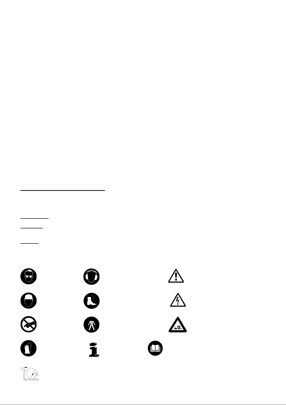
3.2 Chief constituent
4
2
1. Frame
2. Engine
3. Push bow
4. Water tank 30 l
3
6
1
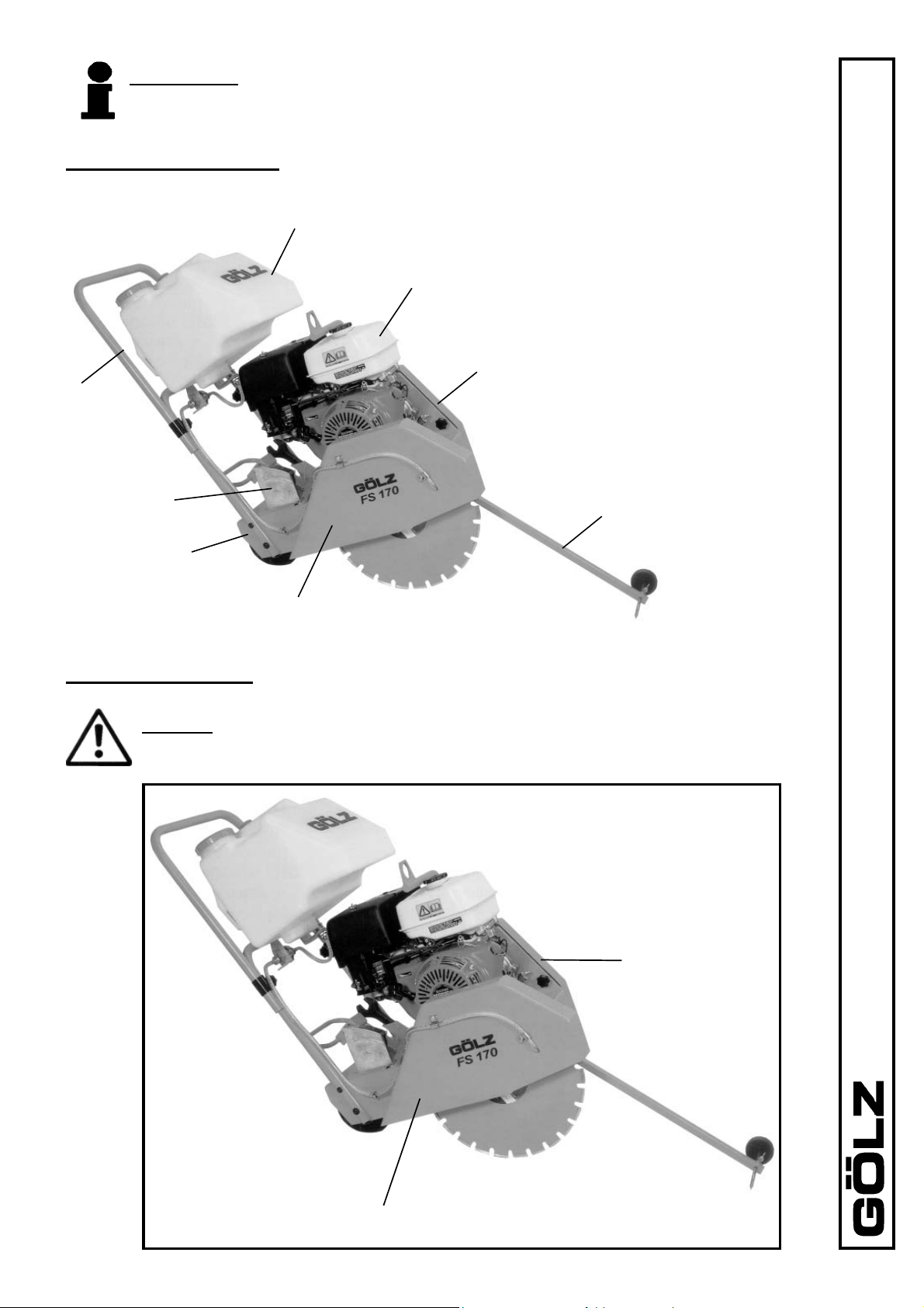
3.3 Safety devices
Danger: During cutting or displacing the fl oor saw, all safety de vic es shown
below must be mounted!
5
7
5. Blade guard
6. Cutting depth indicator
7. V-belt guard
8. Pointer unit
FS 130 /FS170
8
Blade guard
V-belt guard
10
Page 11

3.4 Technical data
FS170 S FS170 SD
17,72"
Ø450 mm -
17,72"
Ø450 mm -
Ø100 mm - 3,94" Ø100 mm - 3,94"
39,37x22,44x31,5"
1000x570x800 mm -
(Ø450)
FS 130 E
FS 130 D FS 130 E
Robin
FS 130 B
17,72"
Ø450 mm -
15,75"
Ø400 mm -
15,75"
Ø400 mm -
15,75"
Ø400 mm -
- 40,55x23,23x39"
1030x590x990 mm
manual start
Yes
Foot pedal
Honda
FS 130 B
Max. cutting
15,75"
depth
Ø400 mm -
Max. blade-Ø
140 mm - 5,5" 140 mm - 5,5" 140 mm - 5,5" 140 mm - 5,5" 160 mm - 6,3" 160 mm - 6,3" 160 mm - 6,3"
25,4 mm - 1" 25,4 mm - 1" 25,4 mm - 1" 25,4 mm - 1" 25,4 mm - 1" 25,4 mm - 1" 25,4 mm - 1"
Flange size Ø90 mm - 3,54" Ø90 mm - 3,54" Ø90 mm - 3,54" Ø90 mm - 3,54" Ø100 mm - 3,94"
Blade shaft
size
Feed manually
11
1000x570x800 mm - 39,37x22,44x31,5"
Watertank 16l or 30l for dry cutting diamond blades
Connection for external water supply wet cutting diamond blades
SStarting de-
vice
V-belt tension continuous
Cutting depth
selector
Cutting depth
control
Dimensions
(LxBXH)
Water supply
Page 12

YANMAR-diesel
engine 3600 rpm,
FS170 S FS170 SD
HONDA-Gas
cooled
7,4kW (10HP)
1 Cylinder, air-
3600 rpm,
9,6 kW (13HP)
engine GX390K1
No load =
108 dB(A)
Full load =
No load =
104 dB(A)
Full load =
No load =
117 dB(A)
No load =
114 dB(A)
95 dB(A)
100 dB(A)
Full load =
88 dB(A)
98 dB(A)
Full load =
(Ø450)
FS 130 E
FS 130 D FS 130 E
YANMAR-diesel
3000 rpm
5,5kW (7,5HP),
3-phase electric
400V, 50 Hz, 16A,
3000 rpm
5,5kW (7,5HP),
3-phase electric
400V, 50 Hz, 16A,
cooled
1 cylinder, air-
engine, 6,6kW
(9HP), 3600 rpm,
No load =
101 dB(A)
Full load =
No load =
101 dB(A)
Full load =
No load =
108 dB(A)
Full load =
No load =
117 dB(A)
No load =
117 dB(A)
No load =
117 dB(A)
85 dB(A)
100 dB(A)
Full load =
85 dB(A)
100 dB(A)
Full load =
95 dB(A)
100 dB(A)
Full load =
FS 130 /FS170
Robin
FS130 B
FS130 B
ROBIN-Gas
Honda
Engine
REG059,
4000 rpm,
engine EX270D
HONDA-Gas
engine GX270SX
6,6 kW (9HP)
3600 rpm,
6,6 kW (9HP)
Empty weight
No load =
No load =
135 kg - 297 lbs 135 kg - 297 lbs 135 kg - 297 lbs 137 kg - 301,4 lbs 137 kg - 301,4 lbs 135 kg - 297 lbs 161 kg - 354 lbs
94 kg - 206,8 lbs 94 kg - 206,8 lbs 105 kg - 231 lbs 100 kg - 220 lbs 100 kg - 220 lbs 104 kg - 229 lbs 120 kg - 264 lbs
Kerb weight
Sound power
level DIN ISO
114 dB(A)
104 dB(A)
Full load =
Full load=
114 dB(A)
104 dB(A)
6393
12
88 dB(A)
No load =
No load =
Sound pressure
level DIN ISO
98 dB(A)
Full load =
88 dB(A)
98 dB(A)
Full load =
6393
67 m/s 74 m/s 58,5 m/s 67 m/s 53 m/s 63 m/s 63 m/s
Max. cutting
3195 rpm 3550 rpm 3195 rpm 3187 rpm 2242 rpm 2690 rpm 2690 rpm
speed
Blade shaft
speed
a = 4,5 m/s² a = 4,5 m/s² a = 9,5 m/s² a = 2,5 m/s² a = 2,5 m/s² a = 4,5 m/s² a = 9,5 m/s²
Vibration
ISO 5349
VDMA 03/2006
Page 13
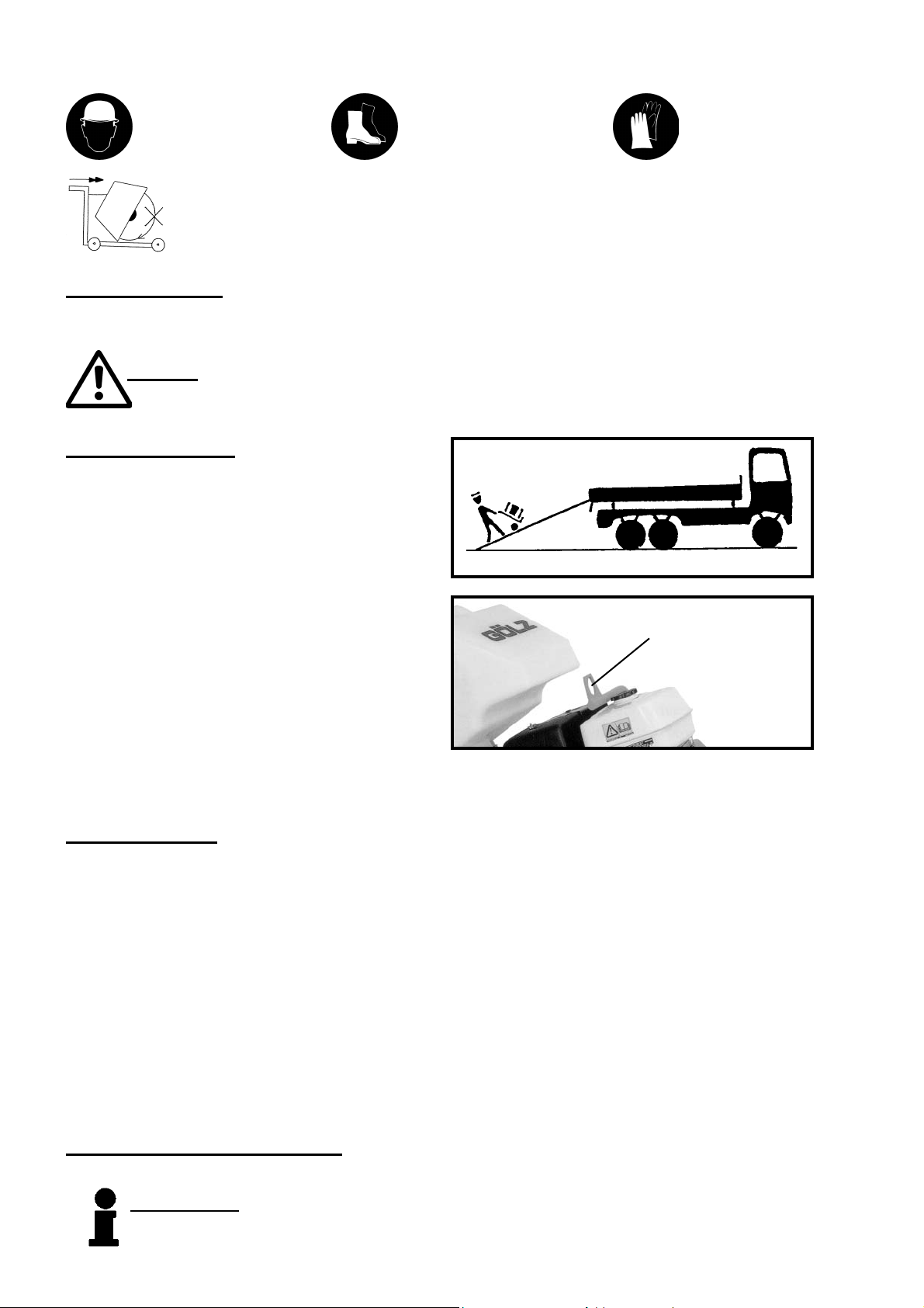
4. Transport
Injury hazard: Down
coming parts!
It is not allowed to move the machine with rotating blade outside of the area
in which cutting works have to be performed!
Injury hazard: Down
coming parts!
4.1 Preparation
Before trans port ing dismount the blade and low er the fl oor saw until to the stop.
Danger: Only use the lifting eye for lifting the fl oor saw!
4.2 Transporting
Check that all parts of the fl oor saw are well fastened
before transporting. Use boards for load and unloading
on a truck. Secure the fl oor saw on the loading area.
Injury hazard:
Sharp edges!
Lifting eye
For loading only use lifting gear and tackle of suffi cient
ca pac i ty (kerb weight of the fl oor saw). Lift the fl oor saw
using the lift ing eye.
5. Installation and operation
5.1 Installation
Place the fl oor saw on an even, fi rm and stable ground. Have the working area well lightened. Keep the
working area clean, cluttered areas invite injuries. Op er at ing the fl oor saw on enclosed premis es, make
sure that there is suffi cient ven ti la tion. Observe the regulations in force at the respective site.
Observe the manufacturer’s information for connecting power and water supply.
Lay all hydraulic lines or cables that damages will be prevented.
Blade mounting
- Mount the blade to the manufacturer’s odds
(Observe the min. fl ange-Ø; use only original screws or nuts).
- Use only blade diameters which are allowed by the manufacturer.
5.2 Initiation and operation
Information: Unconditional observe the owner’s manual of the engine manufacturer!
13
Page 14

Danger: Never touch rotating parts like blade shaft or blade while operating!
Danger: Rotating parts may pull in clothing! Wear tightly cloth ing!
Danger: Down coming parts can cause injuries to the op er a tor!
Operating elements
"0"-position
Main switch
FS 130 /FS170
1
2
1. Foot pedal - rising and low er ing-
2. Depth control
FS 130 E
Cut off the engine or disconnect the power supply before mounting or changing blade.
Information: Clean all fastening devices of the blade (fl anges, thread of the blade
shaft, screws and nuts) before mounting the blade!
The working area is reserved only for the operator. Keep unauthorized persons out of the working
area.
Make sure the operator always has well sight to the working area. He always has to intervene in the
working process.
Never operate the fl oor saw without mounted safety devices.
In the cutting speed range all used blades must be designed for the max. rpm of the fl oor saw.
Never use faulty or damaged blades.
Danger: Faulty or damaged blades can cause injuries to the op er a tor and other
persons!
Check the correct rotation of the blade to the spindle shaft.
Information: Wrong rotation of the blade will result in more wear of the blade!
14
Page 15

Danger: Wrong rotation of the blade may result in segment damage or loss
and can cause injuries to the operator or other persons!
Check the blade is well fastened before beginning to operate.
Use only blades suitable to the blade acceptance (arbor hole, fl anges).
Use only blade suitable to the material to be cut.
Check the correct water fl ow to the blade.
If harmful or explosive stuffs like dust, milk-of-lime arise while cutting, observe local regulations.
Danger: Demolitioning parts can cause injuries to the operator while cut ting!
When travelling on public roads, ways and places always observe the valid traf fi c regulations and, if ne-
cessary, make sure beforehand that the fl oor saw is in a condition compatible with these regulations.
After operating secure the fl oor saw against unintentional moving.
Danger: The sound pressure may exceed 85 dB(A)!
Appropriate to the application of the fl oor saw it could be necessary to wear fur ther protective equip-
ment.
Danger: Down coming parts at the building site can cause in ju ries to the
operator!
Mounting the blade
Cut off the engine before mounting the blade. Mount
a blade with arbor hole of 25.4 mm - 1 in. Check the
correct rotation - arrows on the blade and blade guard.
Attach the blade guard.
Use the fl oor saw only with blades
which have a rated cutting speed
(DIN EN 13236) of 80 m/s!
WS 32
15
Page 16

3
Water supply
1
FS 130 /FS170
2
Danger: Do not use the attached water tank when cutting with wet cutting
diamond blades. The segments may crack off and cause injuries to the operator or bystanders!
Don't exceed the maximum recommended rpm speed for the blade!
Cutting with wet-cutting blades:
Connect the water supply to the GEKA-coupler (1) of the fl oor saw. Check the ball valve (2) is closed (ball
valve lever in 90°-position to the water fl ow). For cutting open the ball valve (2) (ball valve lever in the water
fl ow position).
Cutting with dry-cutting blades:
Fill the water tank with clean water. Connect the GEKA-coupler of the water tank to the GEKA-coupler of the
fl oor saw. Check the ball valve is closed (ball valve lever in 90°-position to the water fl ow). For cutting open the
ball valve (ball valve lever in the water fl ow position) and the valve of the water tank (3).
Cutting operation
FS 130 B/FS 130 D/FS 170 S/FS 170 SD
1
1. Foot pedal - rising and
low er ing-
2. Depth control
2
16
Page 17

Danger: Operating with too high feed the fl oor saw might rise out of cut! In
emergency situations cut off the engine as described in the engines manual!
Completely rise the fl oor saw (blade may have no ground contact). Start the engine as described in the engi-
nes manual. Connect the water supply and slowly lower the fl oor saw with the foot pedal (1) till the blade has
ground contact. Push the depth control to the correct 0-position and slowly lower the fl oor saw to the required
cutting depth. Operating with too high feed the fl oor saw might rise out of cut. After cutting completely rise the
fl oor saw and cut off the engine as described in the engines manual.
Cutting operation FS 130 E
„Triangle“ position
„Star“ position
1
2
1. Foot pedal - rising and low er ing-
2. Depth control
Phase inverter rotation
Danger: Operating with too high feed the fl oor saw might rise out of cut! In
emergency situations cut off the engine as described in the engines manual!
Check the electrical condition - input voltage 380 V/50 Hz. The used power supply must comply with the regulations of power distribution on building sites. Completely uncoil extension cables. The main switch must be on
„0“-position. Insert the mains plug. Completely rise the fl oor saw (blade may have no ground contact). Move
the main switch in triangle position and after some seconds in star position. Notice correct rotation of the
electric motor. W rong rotation - pull mains plug and turn the phase inverter with a screw driver. Repeat
starting and move the starting switch in triangle position after the electric motor has maximum speed. Connect
the water supply and slowly lower the fl oor saw with the foot pedal (1) till the blade has ground contact. Push
the depth control to the correct 0-position and slowly lower the fl oor saw to the required cutting depth. Operating
with too high feed the fl oor saw might rise out of cut. After cutting completely rise the fl oor saw and cut off the
engine . Shut down the electric motor by moving main switch „0“-position.
6. Maintenance
6.1 General
Information: Unconditional observe the owner’s manual of the engine manufacturer, which is added!
17
Page 18

Information: Clean the fl oor saw after eve ry op er a tion. Ob serve local environ-
mental regulations!
Attention: When handling oil, grease and other chemical sub stanc es, observe
the product-related safe ty regulations!
For maintenance jobs the fl oor saw has to be shut down.
For maintenance jobs which must be done while the fl oor saw is running, the blade has to be dismounted
before beginning the job.
6.2 Lubricating chart
Grease the blade shaft bearings after 20 working hours with heat resistance fat. From time to time clean the
foot pedal, pointer unit and wheels and grease them with some drops of oil.
6.3 V-belts
2
FS 130 /FS170
Dismount the leg spring (1) to exchange V-belts.
Move the V-belt tensioner (2) upwards and replace
the V-belts. Mount again the leg spring and close Vbelt guard.
1
18
Page 19

7. Troubleshooting
Attention: In the event of changes in the behaviour of the fl oor saw during
operation, stop the machine immediately and report the mal func tion to the
competent authority/person!
PROBLEM CAUSE REMEDY
Electric motor
Mains plug not connected check connection
Motor does not work! Fuse of power distribution Check fuses
on building sites has been
released
Malfunction of electrical The electrical installation
installation must be checked only
Engine
Fuel tank empty Fill up
Engine does not start!
Dirty fuel lines Clean
Bad engine performance! Dirty air cleaner Clean
For more fault fi nding refer the operating instruction of the engine man u fac tur er
which is enclosed!
Lowering
Floor saw lowers
without actuating Faulty gas pressure spring Replace
the foot pedal!
Floor saw does not Undercarriage or gas Check undercarriage and
fully lower! pressure spring tight gas pressure spring
19
Page 20

PROBLEM CAUSE REMEDY
Cutting
Dull diamond blade Sharpen or use softer
diamond blade
Floor saw rises
out of cut! Faulty gas pressure spring Replace
Feed too high Reduce feed
Damaged centering of Replace blade shaft
the blade shaft
Non circular abrasion
of the diamond blade! Warped blade shaft Replace
Loose or damaged Tighten or replace
blade shaft bearings
No free cut Replace diamond blade
because of sidewards
Diamond blade jams wear-out of segments
in the cut!
Damaged diamond Replace diamond blade
blade core
Insuffi cient water fl ow Check hoses for fracture
free laying
Wrong type of Choose different
Abnormal wear-out diamond blade diamond blade
of segments!
Feed too high Reduce feed
FS 130 /FS170
Cutting in loose under- Reduce cutting depth
ground
Insuffi cient water fl ow Check hoses for fracture
Abnormal blade wear- free laying
out at sides of core!
Cutting in loose under- Reduce cutting depth
ground
Slippy V-belts Adjust
Bad cutting performance!
Blunt diamond blade Sharpen or use softer
diamond blade
20
Page 21

8. Safety checks on electrical systems
8.1 Safety checks on electrical systems according to BGV A2, imple-
mentation instruction clause 1 No.2
Attention: Let any eventual repairs at the electric drive carried out by an electrician
(specialist, specialised work shop) or by Gölz GmbH!
8.1.1 Repetitive checks on stationary electrical systems and operating equipment
System/operating equipment Inspection
period
Electrical systems and stationary
operating equipment
Electrical systems and stationary
electrical operating equipment in
"Special business premises, rooms
and facilities"(DIN VDE 0100 Gruppe 700)
Protective measures with fault current protection facilities in non-stationary systems
Fault current, differential current
and fault voltage circuit breakers
- in stationary systems
- in non-stationary systems 6 months
4 years For proper condition Specialist electrician
1 year
1 month For effectiveness Specialist electrician or
Each working
das
Type of inspection Inspector
person trained in elec-
trical engineering, using
suitable measuring and
test equipment
For fl awless function by
actuating the test facility
User
8.1.2 Repetitive checks on mobile electrical systems and operating equipment
System/operating equipment
- Mobile electrical operating
equipment (if used)
- Extension and device connection cables with plug
devices
- Connection cables with plugs
- Moveable cables with plug
and fi xed connection
Inspection period
guideline and maxi-
mum values
Guideline value 6
months, 3 months on
construction sites.
If a fault rate of <2% is
achieved during the in-
spections, the inspection
period can be extended
accordingly.
Maximum values:
On construction sites,
in production plants
and workshops or under
similar conditions, one
year,
in offi ces or under simi-
lar conditions, two years
Type of inspec-
Inspector
tion
For proper condition Specialist electrician or
person tained in electri-
cal engineering, using
suitable measuring and
test equipment
21
Page 22

Wearing parts for contruction devices mentioned in the operating manual
such as drilling and sawing machines
Wearing parts are the parts subject to operation-related (natural) wear during pro per use of the
device. The wearing time cannot be uniformly defi ned, and differs according to the intensity
of use. The wearing parts must be adjusted, maintained and, if necessary, replaced for the
specifi c device in accordance with the manufacturer’s operating manual. Operation-related
wear is not a reason for defect claims.
• Feed and drive elements such as toothed racks, gearwheels, pinions, spindles,
spindle nuts, spindle bearings, cables, chains, sprockets, belts
• Seals, cables, hoses, packings, connectors, couplings and switches for pneu matic, hydraulic, water, electrical and fuel systems
• Guide elements such as guide strips, guide bushes, guide rails, rollers, bea-
rings, sliding protection supports
• Clamping elements for quick-separating systems
• Flushing head seals
• Slide and roller bearings that do not run in an oil bath
• Shaft oil seals and sealing elements
• Friction and safety clutches, braking devices
• Carbon brushes, commutators/armatures
• Easy-release rings
• Control potentiometers and manual swiching elements
• Securing elements such as plugs, anchors, screws and bolts
• Fuses and lamps
• Auxiliary and operating materials
• Bowden cables
• Discs
• Diaphragms
• Spark plugs, glow plugs
• Parts of the reversing starter such as the starting rope, starting pawl, starting
roller and starting spring
• Sealing brushes, rubber seals, splash protection cloths
• Filters of all kinds
• Drive rollers, defl ection rollers and bandages
• Cable anti-twist elements
• Running and drive wheels
• Water pumps
• Cut-material transport rollers
• Drilling, parting and cutting tools.
FS 130 /FS170
Wearing parts of this machine are marked in the spare parts list page 23 with () and the
spare parts with (#).
22
Page 23

9. Spare parts list
Always indicate:
- machine/model/serial number
- item number and description of the spare part
- amount of spare parts desired
- full address
- goods to be sent by regular mail, express, etc.
Zeichenerklärung
= bestehend aus Pos.
= darin ent hal ten Pos.
= ohne Ab bil dung
= auf Anfrage
= Verschleißteil
# = Ersatzteil
Ä = ab Masch.-Nr.
à = bis Masch.-Nr.
Key to symbols
= consisting of pos.
= including pos.
= not illustrated
= special order
= Wearing part
# = Spare part
Ä = from machine number
à = up to machine number
23
Légende
= se composant des pos.
= y compris pos.
= non illustré
= commande spécial
= Pièce d’usure
# = Pièce de rechange
Ä = a partir de machine Nº
à = jusqu'a machine Nº
Page 24

FS 130 /FS170
Pos. Nr. Type(*) Qty. Bezeichnung - Part name - Désignation
FS170 S 1720001/ FS130 B 1320001
1 0282 130 0554 # 1 Grundgestell - Frame - Embase
2 0282 130 0568 # 1 Aufnahmeplatte 3 0282 130 0551 # 1 Abdeckung Keilriemenscheibe - V-belt pulley guard Capot de protection de poulie pour courroies
4 0282 250 0105 # 4 Scheibe - Washer - Rondelle - B13 DIN 125
5 0285 300 0015 # 4 Mutter - Nut - Ecrou - M12 DIN 982
6 0285 300 0013 # 4 Schraube - Screw - Vis - M12x40 DIN 933 ISO 4017
7 0298 900 0028 # 1 Scheibe - Washer - Rondelle - A8,4 DIN 7349
24
Page 25

Pos. Nr. Type(*) Qty. Bezeichnung - Part name - Désignation
8 0282 130 0565 # 1 Bremspedal - Brake pedal - Pédale de frein
9
FS170
0282 130 0570
FS130
10
11 0282 130 0556 # 2 Schelle - Clip - Clip - BSS 10X25X3
12 0282 130 0566 # 1 Federblech - Sheet metal - Tôle métallique
13 0282 130 0509 # 1 Schubbügeloberteil - Push bow upper part - Poignée
(partie supérieure)
14 0281 045 0073 # 2 Stopfen Griffrohr - Plug - Bouchon en chrome - D20
15 0282 130 0511 # 1 Schubbügelunterteil - Push bow - Poignée
16 0282 130 0508 # 1 Klemme Schubbügel - Clamping device - Blocage
17 0282 130 0531 # 3 Sterngriffschraube - Star grip - Boulon à tête ètoilée -
M8x40 DIN 6336
18 0295 000 0173 # 2 Schraube - Screw - Vis - M10x30 DIN 933 ISO 4017
19 0298 900 0006 # 2 Scheibe - Washer - Rondelle - A 6,4 DIN 9021 ISO 7093
20 0282 130 0015 # 1 Aussenfl ansch - Outer fl ange - Flasque extérieure - FS 130
0282 170 0236 # 1 Aussenfl ansch - Outer fl ange - Flasque extérieure - FS 170
21 0282 130 0014 # 1 Schneidwelle mit Flansch - Blade shaft with fl ange -
Arbre de coupe avec fl asque - FS 130
0282 170 0201 # 1 Schneidwelle mit Flansch - Blade shaft with fl ange -
Arbre de coupe avec fl asque - FS 170
22 0282 170 0067 # 2 Schraube - Screw - Vis - M6x10 DIN 933 ISO 4017
23 0282 170 0057 2 Flanschlager - Flange bearing - Roulement avec fl asque -
UCFL 206 - D30
0285 300 0010 # 2 Schmiernippel Flanschlager - Lubricating nipple -
Fileté de graissage
24 0282 240 0029 # 1 Passfeder - Key - Clavette - 8x7x58 DIN 6885
25 0282 130 0071 # 1 Keilriemenscheibe - V-belt pulley - Poulie pour courroies DW80x3SPZxD30 Taperlock 1210 - FS 130 B/D
0282 170 0233 # 1 Keilriemenscheibe - V-belt pulley - Poulie pour courroies DW95x4SPZxD30 Taperlock 1610 - FS 170 S/SD
0282 130 0034 # 1 Keilriemenscheibe - V-belt pulley - Poulie pour courroies DW80x2SPZxD30 Taperlock 1210 - FS 130 E
0282 170 0204 # 1 Keilriemenscheibe - V-belt pulley - Poulie pour courroies DW95x3SPZxD30- FS 130 E mit Schutzhaube Ø 450
26 0282 130 0029 # 1 Spritzschutz - Splash guard - Carter de protection
27 0298 900 0008 # 1 Scheibe - Washer - Rondelle - A8,4 DIN 9021
28 0282 150 0035 # 1 Schraube - Screw - Vis - M8x20 DIN 933
29 0282 250 0006 # 2 Scheibe - Washer - Rondelle - B 8,4 DIN 125
30 0282 130 0516 # 1
0282 130 0522 # 1
0281 350 0121 # 1
31 0281 045 0028 # 1
32
33 0282 250 0660 # 12 Scheibe - Washer - Rondelle - A6,4 DIN 125
34 0282 250 0649 # 2 Befestigungsschelle - Pipe clamp - Collier de fi xation - D20
35 0281 045 0027 # 6 Mutter - Nut - Ecrou - M6 DIN 982
36 0282 130 0512 # 1 Aufnahme Richtungsanzeiger - Pointer unit Indicateur de direction
37 0282 130 0078 # 1 Richtungspfeil - Pointer arrow - Flêche de direction
38 0282 150 0034 # 1 Flügelschraube - Wing screw - Ecrou à oreilles M8x20 DIN 316
39 0282 120 0084 # 1 Rad - Wheel - Roue - D75x8,2
40 0282 130 0038 # 1 Schnellbefestiger - Quick fi xing device - Dispositif
d'assemblage rapide - D8
41 0281 045 0025 # 2 Mutter - Nut - Ecrou - M8 DIN 934 IS0 4032
42 0282 130 0515 # 1 Tiefenanzeigeskala - Scale - Echelle graduée (profondeur)
43 0295 000 0152 # 2 Schraube - Screw - Vis - M6x25 DIN 933 ISO 4017
44 0295 000 0787 # 1 Schraube - Screw - Vis - M8x10 - DIN 912 ISO 4762
45 0282 120 0045 # 1 Stopfen - Plug - Bouchon - 20x20x1,5-2
46 0282 130 0535 # 1 Klemme Schubbügel - Clamping device - Blocage
47 0282 150 0036 # 1
48 0295 120 0028 # 2 Hutmutter - M12 DIN 917
49
50 0295 000 2031 # 1 Maulschlüssel - Wrench - Clé plate - SW 30 DIN 894
0282 130 0567 # 1
# 1
0282 170 0061 # 2 Schraube - Screw - Vis - M8x10 DIN 933 ISO 4017
0282 250 0804 # 4 Schraube - Screw - Vis - M6x60 DIN 933
0295 000 2044 # 1 Maulschlüssel - Wrench - Clé plate - SW 32 DIN 894
Schutzhaube Keilriemen - V-belt guard - Capot de protection -
Schutzhaube Keilriemen - V-belt guard - Capot de protection -
Schutzhaube - Blade guard - Capot de protection
Schutzhaube - Blade guard - Capot de protection
Schutzhaube - Blade guard - Capot de protection
Sterngriffschraube - Star grip - Boulon à tête ètoilée - M10x25
Federring - Spring washer - Rondelle élastique - A8 DIN 127
- D=350
- D=450
- D=400
25
Page 26

Ersatzteile für Maschinen älterer Bauart - Spare parts for previous models - Pièces de rechange pour machines d´ancienne construction
FS 130 /FS170
Pos. Nr. Type(*) Qty. Bezeichnung - Part name - Désignation
1 0282 130 0547 # 1 Grundgestell - Frame - Embase
2 0295 000 3506 # 4 Schraube - Screw - Vis - M8x25 DIN 7380
3 0282 130 0501 # 1 Abdeckung Keilriemenscheibe - V-belt pulley guard Capot de protection de poulie pour courroies
4 0282 250 0105 # 8 Scheibe - Washer - Rondelle - B13 DIN 125
5 0285 300 0015 # 4 Mutter - Nut - Ecrou - M12 DIN 982
6 0285 300 0018 # 2 Schraube - Screw - Vis - M12x45 DIN 933
7 0298 900 0028 # 1 Scheibe - Washer - Rondelle - A8,4 DIN 7349
8 0282 150 0036 # 7
9 0282 130 0506 # 1
10 0282 130 0102 # 2 Schraube - Screw - Vis - M8x30 DIN 603
11 0282 240 0101 # 2 Schelle - Clip - Clip - D12
12 0281 045 0025 # 7 Mutter - Nut - Ecrou - M8 DIN 934
13 0282 130 0509 # 1 Schubbügeloberteil - Push bow upper part - Poignée
(partie supérieure)
14 0281 045 0073 # 2 Stopfen Griffrohr - Plug - Bouchon en chrome - D20
15 0282 130 0511 # 1 Schubbügelunterteil - Push bow - Poignée
Federring - Spring washer - Rondelle élastique - A8 DIN 127
Schutzhaube Keilriemen - V-belt guard - Capot de protection
26
Page 27

Pos. Nr. Type(*) Qty. Bezeichnung - Part name - Désignation
16 0282 130 0508 # 1 Klemme Schubbügel - Clamping device - Blocage
17 0282 130 0531 # 3 Sterngriffschraube - Star grip - Boulon à tête ètoilée -
M8x40 DIN 6336
18 0295 000 3511 # 4 Schraube - Screw - Vis - M10x30 DIN 7380
19 0282 130 0548 # 1 Versteifungsplatte - Stiffening plate - Tôle de plaque
20 0282 130 0015 # 1 Aussenfl ansch - Outer fl ange - Flasque extérieure - FS 130
0282 170 0202 # 1 Aussenfl ansch - Outer fl ange - Flasque extérieure - FS 170
21 0282 130 0014 # 1 Schneidwelle mit Flansch - Blade shaft with fl ange -
Arbre de coupe avec fl asque - FS 130
0282 170 0201 # 1 Schneidwelle mit Flansch - Blade shaft with fl ange -
Arbre de coupe avec fl asque - FS 170
22 0282 120 0008 4 Buchse - Bushing - Douille - A=16, I=12, L=12
23 0282 250 0022 2 Flanschlager - Flange bearing - Roulement avec fl asque -
UCFL 206
0285 300 0010 # 2 Schmiernippel Flanschlager - Lubricating nipple -
Fileté de graissage
24 0282 240 0029 # 1 Passfeder - Key - Clavette - 8x7x58 DIN 6885
25 0282 130 0071 # 1 Keilriemenscheibe - V-belt pulley - Poulie pour courroies DW80x3SPZxD30 Taperlock 1210 - FS 130 B/D
0282 170 0233 # 1 Keilriemenscheibe - V-belt pulley - Poulie pour courroies DW95x4SPZxD30 Taperlock 1610 - FS 170 S/SD
0282 130 0034 # 1 Keilriemenscheibe - V-belt pulley - Poulie pour courroies DW80x2SPZxD30 Taperlock 1210 - FS 130 E
0282 170 0204 # 1 Keilriemenscheibe - V-belt pulley - Poulie pour courroies DW95x3SPZxD30- FS 130 E mit Schutzhaube Ø 450
26 0282 130 0029 # 1 Spritzschutz - Splash guard - Carter de protection
27 0298 900 0008 # 1 Scheibe - Washer - Rondelle - A8,4 DIN 9021
28 0282 150 0035 # 1 Schraube - Screw - Vis - M8x20 DIN 933
30 0282 130 0516 # 1
0282 130 0522 # 1
0281 350 0121 # 1
31 0281 045 0028 # 1
32 0282 250 0804 # 4 Schraube - Screw - Vis - M6x60 DIN 933
33 0282 250 0660 # 8 Scheibe - Washer - Rondelle - A6,4 DIN 125
34 0282 250 0649 # 2 Befestigungsschelle - Pipe clamp - Collier de fi xation - D20
35 0281 045 0027 # 6 Mutter - Nut - Ecrou - M6 DIN 982
36 0282 130 0512 # 1 Aufnahme Richtungsanzeiger - Pointer unit - Indicateur de
direction
37 0282 130 0078 # 1 Richtungspfeil - Pointer arrow - Flêche de direction
38 0282 150 0034 # 1 Flügelschraube - Wing screw - Ecrou à oreilles M8x20 DIN 316
39 0282 120 0084 # 1 Rad - Wheel - Roue - D75x8,2
40 0282 130 0038 # 1 Schnellbefestiger - Quick fi xing device - Dispositif
d'assemblage rapide - D8
41 0285 300 0013 # 2 Schraube - Screw - Vis - M12x40 DIN 933
42 0282 130 0515 # 1 Tiefenanzeigeskala - Scale - Echelle graduée (profondeur)
43 0295 000 0152 # 1 Schraube - Screw - Vis - M6x25 DIN 933 ISO 4017
44 0285 300 0141 # 1 Schraube - Screw - Vis - M6x30 DIN 933 ISO 4017
45 0282 120 0045 # 1 Stopfen - Plug - Bouchon - 20x20x1,5-2
46 0282 130 0535 # 1 Klemme Schubbügel - Clamping device - Blocage
47 0282 250 0661 # 4 Scheibe - Washer - Rondelle - A8,4 DIN 125
48 0282 150 0040 # 1 Schraube - Screw - Vis - M10x80 DIN 933 ISO 4017
49 0295 600 0528 # 1 Druckfeder - Pressure spring - Ressort - 10,4x0,9x41,6
50 0286 570 0046 # 1 Mutter - Nut - Ecrou - M10 DIN 934 ISO 4032
51 0282 150 0032 # 1 Sterngriff - Star grip - Boulon à tête ètoilée - M10 DIN 6336
52 0295 000 2044 # 1 Maulschlüssel - Wrench - Clé plate - SW 32 DIN 894
0298 100 0112 # 0,72m Kantenschutz - Edge protection - Protège-arête
0298 100 0212 # 4 cm Kraftstoffschlauch - Fuel pipe line - Conduite de carburant
SchutzhaubE - Blade guard - Capot de protection
Schutzhaube - Blade guard - Capot de protection
Schutzhaube - Blade guard - Capot de protection
Sterngriffschraube - Star grip - Boulon à tête ètoilée - M10x25
- D=350
- D=450
- D=400
Ersatzteile für Maschinen älterer Bauart - Spare parts for previous models - Pièces de rechange pour machines d´ancienne construction
Pos. Nr. Type(*) Qty. Bezeichnung - Part name - Désignation
FS 170 S 170 0614/FS 170 SD 17 660
25 0282 170 0204 # 1 Keilriemenscheibe - V-belt pulley - Poulie pour courroies DW95x3SPZxD30 Taperlock 1610 - FS 170 S
27
Page 28

FS 130 /FS170
28
Page 29

Pos. Nr. Type(*) Qty. Bezeichnung - Part name - Désignation
1 0282 130 0557 # 1 Fahrwerk - Undercarriage - Châsis
2 0282 250 0074 # 2 Mutter - Nut - Ecrou - M14 DIN 982
3 0295 120 0028 # 2
4
5 0295 600 1043 # 2 Scheibe - Washer - Rondelle - B15 DIN 125
6 0282 130 0017 # 2 Rad vorne - Wheel - Roue - V125/15R
7 0282 250 0118 # 1 Schraube - Screw - Vis - M10x50 DIN 933
8 0286 570 0046 # 1 Mutter - Nut - Ecrou - M10 DIN 934
9 0282 130 0018 # 1 Gasdruckfeder - Gas pressure spring - Amortisseur
pneumatique
10 0282 130 0559 # 1 Hinterachse - Rear axle - Transmission arrière - FS170 S
11 0282 130 0019 # 1 Gas druck fe der auf nah me - Gas pressure spring support -
Fixation de l'amortisseur
12 0282 170 0226 # 2 Schraube - Screw - Vis - M8x12 DIN 912 ISO 4762
13 0282 130 0026 # 1 Zylinderstift - Straight pin - Cheville - 8x20 m6
14 0282 130 0562 # 1 Pedal - Foot pedal - Pédale
15 0282 170 0009 # 1 Schraube - Screw - Vix - M6x80 DIN 931 ISO 4014
16 0286 570 0069 # 2 Scheibe - Washer - Rondelle - B6,4 DIN 125
17 0281 045 0027 # 1 Mutter - Nut - Ecrou - M6 DIN 982
18 9007 319 1880 # 1 Schraube - Screw - Vis - M8x35 DIN 931 ISO 4014
19 0282 140 0002 # 2 Rad hinten - Wheel - Roue - D160xD20 58 mm
20 0282 130 0023 # 1 Tie fen an zei ger - Depth cutting indicator - Indicateur de
profondeur
21 0282 130 0044 # 1 Befestigungsschelle mit Schrau ben - Clip with screws Bride avec vis - D30
22 0282 130 0024 # 2 Lagerbuchse - Bushing - Coussinet
23 0282 130 0558 # 1 Schutzhülse - Protective ring - Douille
24 0282 065 0005 # 1 Mutter - Nut - Ecrou - M8 DIN 982
0282 130 0564 # 1 Gewindestange - thread rod - Tige fi letée - M12x470
Hutmutter - M12 DIN 917
29
Page 30

Ersatzteile für Maschinen älterer Bauart - Spare parts for previous models - Pièces de rechange pour machines d´ancienne construction
FS 130 /FS170
30
Page 31

Pos. Nr. Type(*) Qty. Bezeichnung - Part name - Désignation
1 0282 130 0016 # 1 Fahrwerk - Undercarriage - Châsis
2 0282 130 0037 # 1 Bolzen - Bolt - Axe - D8x128
3 0282 130 0038 # 2 Schnell be festiger - Quick fi xing device - Dispositif
d'assemblage rapide - D8
4 0284 650 0046 # 2 Splint - Split pin - Goupille - 4x25 DIN 94
5 0282 250 0023 # 2 Scheibe - Washer - Rondelle - B17 DIN 125
6 0282 130 0017 # 2 Rad vorne - Wheel - Roue - V125/15R
7 0282 250 0118 # 1 Schraube - Screw - Vis - M10x50 DIN 933
8 0286 570 0046 # 1 Mutter - Nut - Ecrou - M10 DIN 934
9 0282 130 0018 # 1 Gasdruckfeder - Gas pressure spring - Amortisseur
pneumatique
10 9211 260 1340 # 1 Mutter - Nut - Ecrou - M10x1 DIN 936
11 0282 130 0019 # 1 Gas druck fe der auf nah me - Gas pressure spring support Fixation de l'amortisseur
12 0282 170 0226 # 2 Schraube - Screw - Vis - M8x12 DIN 912
13 0282 130 0026 # 1 Zylinderstift - Straight pin - Cheville - 8x20 m6
14 0282 130 0513 # 1 Pedal - Foot pedal - Pédale
15 0282 130 0021 # 1 Bolzen für Pedal - Bolt - Axe
16 0282 130 0022 # 2 Schnell be festiger - Quick fi xing device - Dispositif
d'assemblage rapide - D6
17 0295 000 3520 # 2 Schraube - Screw - Vis - M12x25 DIN 7380
18 0282 250 0105 # 2 Scheibe - Washer - Rondelle - B13 DIN 125
19 0282 140 0002 # 2 Rad hinten - Wheel - Roue - D160xD20 58 mm
20 0282 130 0023 # 1 Tie fen an zei ger - Depth cutting indicator - Indicateur de
profondeur
21 0282 130 0044 # 1 Befestigungsschelle mit Schrau ben - Clip with screws Bride avec vis - D30
22 0282 130 0024 # 2 Lagerbuchse - Bushing - Coussinet
23 0282 130 0025 # 1 Hinterachse - Rear axle - Transmission arrière
31
Page 32

FS 130 /FS170
Ersatzteile für Maschinen älterer Bauart - Spare parts for previous models - Pièces de rechange pour machines d´ancienne construction
32
Page 33

Pos. Nr. Type(*) Qty. Bezeichnung - Part name - Désignation
-- 0282 130 0070 # 1 Wassertank - Water tank - Réservoir d'eau - 16 l
Pos.1-6, 9-12
-- 0282 130 0528 # 1 Wassertank - Water tank - Réservoir d'eau - 30 l -
Pos.1-12
1 0282 140 0073 # 1 Wassertank ohne Deckel - Water tank without cap Réservoir d'eau sans couvercle
0282 130 100 # 1 Wassertank ohne Deckel - Water tank without cap Réservoir d'eau sans couvercle - 30 l
4 4202 709 2000 1 Dichtring - Packing ring - Anneau d'étanchéité
5 4202 701 0900 # 1 Be häl ter dec kel - Cap - Couvercle du réservoir
6 4201 703 2600 # 1 Ab sperr schie ber - Stop valve - Vanne d'arrêt
7 0282 130 0533 # 1 Gewindestift - Set screw - Vis sans tête - M3x4 DIN 913
8 0282 130 0525 # 1 Verlängerung Tankverschluss - Lengthening piece -Allonge
9 0282 140 0074 1 O-Ring - O-ring - Joint torique - 6x1,5 DIN 3770
10 9208 260 1660 # 1 Mutter - Nut - Ecrou - BM16x1,5 DIN 439
11 0295 000 0164 1 Dichtring - Packing ring - Anneau d'étanchéité 18x24A DIN 7603
12 4201 708 8800 # 1 Ventil - Valve - Valve
13 0295 000 0176 1 O-Ring - O-ring - Joint torique - 14x2,5 DIN 3770
14 0282 120 0521 # 1 An schluss stut zen - Connection piece - Raccord
15 0282 250 0105 # 1 Scheibe - Washer - Rondelle - B13 DIN 125
16 0298 900 0013 # 2 Scheibe - Washer - Rondelle - B13 DIN 9021
17 0281 350 0060 # 1 Schlauchtülle - Nozzle - Embout à olive - 1/4"x10D Innen
18 0295 000 0581 # 3 2-Ohr-Schelle - Clip - Clip - D15-17
19 0298 100 0103 # 0,3m Schlauch - Hose - Tuyau - 9x3
20 0295 000 0644 # 2 Schlauchtülle - Nozzle - Embout à olive - 1/2"x9D
21 0282 170 0032 # 2 GEKA-Kupplung - GEKA-coupler - Raccord GEKA - G1/2"
22 0286 570 0069 # 3 Scheibe - Washer - Rondelle - B 6,4 DIN 125
23 0282 140 0040 # 1 Minikugelhahn - Ball valve - Robinet à boisseau sphérique R1/2"
24 0298 100 0103 # 1,2m Schlauch - Hose - Tuyau - 9x3
25 9008 319 1280 # 3 Schraube - Screw - Vis - M6x16 DIN 933
26 0282 240 0101 # 2 Schelle - Clip - Clip - D12
27 0285 300 0142 # 3 Mutter - Nut - Ecrou - M6 DIN 934
28 0282 130 0523 # 0,4m Schlauch - Hose - Tuyau - 6x2 - D=350
0282 130 0523 # 0,5m Schlauch - Hose - Tuyau - 6x2 - D=400
0282 130 0523 # 0,6m Schlauch - Hose - Tuyau - 6x2 - D=450
29 0282 130 0527 # 1 Y-Verteiler - Connection - Raccord - RY 6-8-6
30 0282 130 0532 # 1 Schelle - Clip - Clip - D15
0282 130 0541 # 0,4m Schlauch - Hose - Tuyau - PAN-L-6x1
Ersatzteile für Maschinen älterer Bauart - Spare parts for previous models - Pièces de rechange pour machines d´ancienne construction
Pos. Nr. Type(*) Qty. Bezeichnung - Part name - Désignation
1 0282 170 0030 # 2 Schlauchtülle - Nozzle - Embout à olive - 1/2"x6D
2 0295 000 0229 # 4 2-Ohr-Schelle - Clip - Clip - D11-13
3 0282 130 0063 # 1 Schlauch - Hose - Tuyau - 6x350 mm
4 0282 130 0035 # 1 Schlauchtülle - Nozzle - Embout à olive - R1/4" LW D6
5 0282 130 0039 # 1 Re du zier nip pel - Reduction - Réducteur - 1/8"-1/4"
6 0282 130 0006 # 1
Schutzhaube Trennscheibe - Blade guard - Capot de protection
- D=350
7 0282 130 0057 # 1 Steck ver schrau bung - Connection - Douille-raccord
8 0282 130 0041 # 2 Schlauch - Hose - Tuyau - 330 mm Pos.27
9 0282 130 0065 # 2 2-Ohr-Schelle - Clip - Clip - D5-7
33
Page 34

Elektromotor - Electric motor - Moteur électrique
FS 130 /FS170
Pos. Nr. Type(*) Qty. Bezeichnung - Part name - Désignation
1 0282 130 0980 # 1 Elektromotor - Electric motor - Moteur électrique - 5,5 kW
2 0282 150 0055 # 2 Schraube - Screw - Vis - M10x45 DIN 933
3 0295 000 0216 # 6 Scheibe - Washer - Rondelle - A10,5 DIN 7349
4 0286 570 0052 # 4 Mutter - Nut - Ecrou - M10 DIN 982
5 0282 130 0521 # 1 Transportbügel - Lifting eye - Anneau de levage
34
Page 35

Pos. Nr. Type(*) Qty. Bezeichnung - Part name - Désignation
6 0295 000 0325 # 2 Schraube - Screw - Vis - M10x65 DIN 931
7 0286 570 0047 # 2 Scheibe - Washer - Rondelle - B10,5 DIN 125
8 0286 570 0069 # 4 Scheibe - Washer - Rondelle - B6,4 DIN 125
9 0281 045 0027 # 2 Mutter - Nut - Ecrou - M6 DIN 982
10 0267 112 5047 # 2 Schraube - Screw - Vis - M6x20 DIN 912
11 0282 240 0989 # 1 Motorschalter - Starter - Commande moteur
12 0295 601 0016 # 3 Gewindestift - Set screw - Vis sans tête - M8x55 DIN 913
13 0282 130 0524 # 3 Mutter - Nut - Ecrou - M8x3d DIN 6334
14 0281 045 0025 # 9 Mutter - Mut - Ecrou - M8 Din 934
15 0282 250 0006 # 8 Scheibe - Washer - Rondelle - B8,4 DIN 125
16 0266 240 0039 # 3 Schraube - Screw - Vis - M8x20 DIN 7991
17 0282 150 0027 # 2 Schraube - Screw - Vis - M8x40 DIN 933
18 0285 300 0985 # 1 Passfeder - Key - Clavette - 10x8x70 DIN 6885
19 0282 130 0047 # 1 Keilriemenscheibe - V-belt pulley - Poulie pour courroies
DW85x2SPZxD38 Taperlock 1610
0282 170 0046 # 1 Keilriemenscheibe - V-belt pulley - Poulie pour courroies
DW71x3SPZxD38 -FS 130 E mit Schutzhaube Ø 450
20 9289 021 0190 # 1 Scheibe - Washer - Rondelle - R9 DIN 440-St
21 0281 045 0024 # 1 Schraube - Screw - Vis - M8x30 DIN 933
22 0282 130 0530 2 Keilriemen - Set of V-belts - Jeu de courroies - XPZ 787 LW
0282 130 0549 3 Keilriemen - Set of V-belts - Jeu de courroies - XPZ 800 LW -
FS130 E mit Schutzhaube Ø 450
23 0282 130 0518 # 1 Halter Keilriemenspanner - V-belt tensioning device fi xing -
Fixation de dispositif tendeur
24 0282 130 0517 # 1 Keilriemenspanner - V-belt tensioning device Dispositif tendeur
25 0285 300 0090 # 1 Scheibe - Washer - Rondelle - B21 DIN 125
26 0282 250 0096 2 Lager - Bearing - Roulement à billes - 6304.2RS DIN 625
27 0282 130 0519 # 1 Buchse - Bushing - Douille
28 0282 130 0510 1 Rolle Keilriemenspanner - V-belt tensioning device roller Poulie fi xation de dispositif tendeur
29 0298 900 0008 # 2 Scheibe - Washer - Rondelle - A8,4 DIN 9021
30 0295 0003505 # 1 Schraube - Screw - Vis - M8x20 DIN 7380
31 0282 130 0534 # 1 Schraube - Screw - Vis - M8x75 DIN 933
32 0282 130 0500 # 1 Schenkelfeder - Leg spring - Ressort à branches
33 0282 250 0005 # 1 Schraube - Screw - Vis - M8x16 DIN 933
34 0282 130 0514 # 1 Aufnahmeplatte Elektro - Attachment plate - Plaque
0282 130 0054 # 1 Distanzring für Motorschalter - Distance ring for starter Anneau d’écartement pour commande de moteur
0298 100 0030 # 1 Gegenmutter - Counter nut - Contre-écrou - M32x1,5
0298 100 0065 # 1 T+B Verschraubung - T+B connection - Raccord T+B PG 16
0298 100 0033 # 1 Reduzierung - Reduction - Réducteur - 6kt M32/PG16
0298 100 0081 # 6 Aderendhülse - End sleeve for strands - Anneau conducteur 2,5 mm
2
0298 100 0083 # 6 Kabelöse - Ring cable bracket - Anneau de câble - Nr. 2123
0298 100 0091 # 2 Kabelschuh - Cable bracket - Cosse de câble - 1,5-2,5 mm
0298 100 0100 # 0,08m Anaconda-Schlauch - Hose - Tuyau
0298 100 0220 # 0,9m Kabel - Cable - Câble - 7x2,5 mm2 H07RNF
0298 100 0013 # 1 Schutzschlauch - Protection hose - Gaine - PG 13,5
0298 100 0017 # 2 Kabelverschraubung - Connection - Raccord - V-M25
2
35
Page 36

Dieselmotor - Diesel engine - Moteur diesel
FS 130 /FS170
FS 170 SD
FS 130 D
Pos. Nr. Type(*) Qty. Bezeichnung - Part name - Désignation
1 0282 130 0076 # 1 Motor - Engine - Moteur - YANMAR L90AE - FS 130 D
0282 170 0076 # 1 Motor - Engine - Moteur - YANMAR L100AE - FS 170 SD
2 0282 130 0520 # 1 Buchse - Bushing - Douille
3 0282 130 0503 # 1 Aufnahmeplatte Keilriemenspanner - Attachment plate Plaque
4 0282 250 0006 # 3 Scheibe - Washer - Rondelle - B8,4 DIN 125
5 0282 150 0035 # 2 Schraube - Screw - Vis - M8x20 DIN 933
6 0281 045 0025 # 2 Mutter - Mut - Ecrou - M8 DIN 934
36
Page 37

Pos. Nr. Type(*) Qty. Bezeichnung - Part name - Désignation
7 0282 450 0120 # 1 Schraube - Screw - Vis - M8x50 DIN 933
8 0282 120 0096 # 1 Passfeder - Key - Clavette
9 0282 170 0209 # 1 Keilriemenscheibe - V-belt pulley - Poulie pour courroies DW71x3SPZxD25 - FS 130 D
0282 170 0234 # 1 Keilriemenscheibe - V-belt pulley - Poulie pour courroies DW71x4SPZxD25 - FS 170 SD
10 0282 170 0007 1 Satz Keilriemen - Set of V-belts - Jeu de courroies 3x XPZ-812LW - FS 130 D
0282 120 0097 4 Keilriemen - V-belt - Courroies - XPZ-850LW - FS 170 SD
11 0282 170 0235 # 1 Scheibe - Washer - Rondelle
12 0295 000 0329 # 1 Schraube - Screw - Vis - M8x30 DIN 7991
13 0282 130 0518 # 1 Halter Keilriemenspanner - V-belt tensioning device fi xing -
Fixation de dispositif tendeur
14 0282 130 0517 # 1 Keilriemenspanner - V-belt tensioning device Dispositif tendeur
15 0285 300 0090 # 1 Scheibe - Washer - Rondelle - B21 DIN 125
16 0282 250 0096 2 Lager - Bearing - Roulement à billes - 6304.2RS DIN 625
17 0282 130 0519 # 1 Buchse - Bushing - Douille
18 0282 130 0510 1 Rolle Keilriemenspanner - V-belt tensioning device roller Poulie fi xation de dispositif tendeur - FS 130 D
0282 130 0542 1 Rolle Keilriemenspanner - V-belt tensioning device roller Poulie fi xation de dispositif tendeur - FS 170 SD
19 9289 021 0190 # 2 Scheibe - Washer - Rondelle - R9 DIN 440-St
20 0295 000 3505 # 1 Schraube - Screw - Vis - M8x20 DIN 7380
21 0282 130 0534 # 1 Schraube - Screw - Vis - M8x75 DIN 933
22 0282 130 0500 # 1 Schenkelfeder - Leg spring - Ressort à branches
23 0282 130 0538 # 1 Verschlußstopfen - Plug - Bouchon de purge - VSTI 12x1,5
24 0282 130 0539 # 1 Schlauch - Hose - Tuyau - DN06x200
25 0282 130 0529 # 1 Nippel - Nipple - Niple - GE 08L-M16x1,5
26 0295 000 0035 # 2 Schraube - Screw - Vis - M10x40 DIN 933
27 0295 000 0216 # 6 Scheibe - Washer - Rondelle - A10,5 DIN 7349
28 0286 570 0052 # 6 Mutter - Nut - Ecrou - M10 DIN 982
29 0282 250 0118 # 2 Schraube - Screw - Vis - M10x50 DIN 933 ISO 4017
30 0282 150 0027 # 1 Schraube - Screw - Vis - M8x40 DIN 933
31 0282 130 0507 # 1 Transportbügel - Lifting eye - Anneau de levage
32 0267 113 0095 # 1 Schelle - Hose clamp - Bride - Norma RSGU 20-22
33 0295 000 3505 # 1 Schraube - Screw - Vis - M8x20 DIN 7380
34 0282 065 0005 # 1 Mutter - Nut - Ecrou - M 8 DIN 982
0298 000 1006 # 1 Motoröl - SAE 15 W40
Ersatzteile für Maschinen älterer Bauart - Spare parts for previous models - Pièces de rechange pour machines d´ancienne construction
Pos. Nr. Type(*) Qty. Bezeichnung - Part name - Désignation
FS 170 SD 17 660
9 0282 170 0209 # 1 Keilriemenscheibe - V-belt pulley - Poulie pour courroies DW71x3SPZxD25 - FS170 SD
10 0282 120 0097 3 Keilriemen - V-belts - Courroies - XPZ-850LW - FS 170 SD
11 9289 021 0190 # 1 Scheibe - Washer - Rondelle - R9 DIN 440-St
12 0281 045 0024 # 1 Schraube - Screw - Vis - M8x30 DIN 933
19 0298 900 0008 # 2 Scheibe - Washer - Rondelle - A8,4 DIN 9021
20 0282 130 0510 1 Rolle Keilriemenspanner - V-belt tensioning device roller Poulie fi xation de dispositif tendeur- FS170 SD
37
Page 38

Benzinmotor - Gas engine - Moteur
HONDA
FS 130 /FS170
38
Page 39

Pos. Nr. Type(*) Qty. Bezeichnung - Part name - Désignation
1 0282 130 0950 # 1 Motor - Engine - Moteur - HONDA GX270SX - FS 130 B
0282 130 0960 # 1 Motor - Engine - Moteur - ROBIN EX270D - FS 130 B
0282 170 0950 # 1 Motor - Engine - Moteur - HONDA GX390K1 - FS 170 S
2 0282 130 0520 # 1 Buchse - Bushing - Douille
3 0295 000 0216 # 4 Scheibe - Washer - Rondelle - A10,5 DIN 7349
4 0282 150 0035 # 1 Schraube - Screw - Vis - M8x20 DIN 933 ISO 4017
5 0282 150 0036 # 1 Federring - A8 DIN 127
6 0266 350 0105 # 1 Schraube - Screw - Vis - M8x35 DIN 7991
7 0282 130 0561 # 1 Flachstahl - Flat steel - Acier plate - 30x15x30
8 0282 130 0560 # 1 Gummipuffer - Rubber pad - Buffer
9 GX2000000 # 1 Defl ektor - Defl ector - Défl ecteur - GX
10 0282 120 0096 # 1 Passfeder - Key - Clavette
11 0282 170 0232 # 4 Keilriemen - V-belts - Courroies - XPZ-787LW - FS 170 S
0282 170 0205 3 Keilriemen - V-belts - Courroies - XPZ-750LW - FS130 B
12 0282 170 0209 # 1 Keilriemenscheibe - V-belt pulley - Poulie pour courroies DW71x3SPZxD25 - FS 130 B
0282 170 0234 # 1 Keilriemenscheibe - V-belt pulley - Poulie pour courroies DW71x4SPZxD25 - FS 170 S
13 0282 170 0235 # 1 Scheibe - Washer - Rondelle
14 0282 130 0518 # 1 Halter Keilriemenspanner - V-belt tensioning device fi xing -
Fixation de dispositif tendeur
15 0282 130 0563 # 1 Keilriemenspanner - V-belt tensioning device Dispositif tendeur
16 0285 300 0090 # 2 Scheibe - Washer - Rondelle - B21 DIN 125
17 0282 450 0520 # 1 Nippel - Nipple - Niple - GE 08L-M12x1,5 - HONDA
18 0282 250 0096 2 Lager - Bearing - Roulement à billes - 6304.2RS DIN 625
19 0282 130 0519 # 1 Buchse - Bushing - Douille
20 0282 130 0510 1 Rolle Keilriemenspanner - V-belt tensioning device roller Poulie fi xation de dispositif tendeur - FS 130 B
0282 130 0542 1 Rolle Keilriemenspanner - V-belt tensioning device roller Poulie fi xation de dispositif tendeur - FS 170 S
21 9289 021 0190 # 2 Scheibe - Washer - Rondelle - R9 DIN 440-St
22 0282 450 0120 # 4 Schraube - Screw - Vis - M8x50 DIN 933 ISO 4017
23 0282 130 0534 # 1 Schraube - Screw - Vis - M8x75 DIN 933 ISO 4017
24 0282 130 0500 # 1 Schenkelfeder - Leg spring - Ressort à branches
25 0282 130 0539 # 1 Schlauch - Hose - Tuyau - DN06x200
26 0282 130 0538 # 1 Verschlußstopfen - Plug - Bouchon de purge - 08L
27 0282 250 0118 # 4 Schraube - Screw - Vis - M10x50 DIN 933 ISO 4017
28 0286 570 0047 # 8 Scheibe - Washer - Rondelle - B10,5 DIN 125
29 0286 570 0052 # 4 Mutter - Nut - Ecrou - M10 DIN 982
30 0267 113 0095 # 1 Schelle - Hose clamp - Bride - Norma RSGU 20-22
31 0281 045 0025 # 1 Mutter - Nut - Ecrou - M8 DIN 934 ISO 4032
32 0282 150 0027 # 1 Schraube - Screw - Vis - M8x40 DIN 933 ISO 4017
33 0281 045 0025 # 3 Mutter - Nut - Ecrou - M8 DIN 934 ISO 4032
34 0298 100 0023 # 1 Blientniet - D6x10
0282 130 0215 # 1 Kabel - Cable - Câbles - 1x1,5mm²
0298 100 0004 # 5 Kabelband - Cable tape - Protecteur de câbles - KS 3-75
0282 130 0212 # 1 Schalter f. Motorstop - Switch for engine stop - Interrupteur
0282 130 0094 # 1 Abzweigverbinder
0298 000 1006 # 1 Motoröl - Motor oil - Huille - SAE 15 W40
39
Page 40

Ersatzteile für Maschinen älterer Bauart - Spare parts for previous models - Pièces de rechange pour machines d´ancienne construction
Benzinmotor - Gas engine - Moteur
HONDA / ROBIN
FS 130 /FS170
FS 170 S
FS 170 S
FS 130 B
FS 130 B
Pos. Nr. Type(*) Qty. Bezeichnung - Part name - Désignation
1 0282 130 0950 # 1 Motor - Engine - Moteur - HONDA GX270SX - FS 130 B
0282 130 0960 # 1 Motor - Engine - Moteur - ROBIN EX270D - FS 130 B
0282 170 0950 # 1 Motor - Engine - Moteur - HONDA GX390K1 - FS 170 S
2 0282 130 0520 # 1 Buchse - Bushing - Douille
3 0282 130 0502 # 1 Transportbügel - Lifting eye - Anneau de levage
4 0282 130 0503 # 1 Aufnahmeplatte Keilriemenspanner - Attachment plate Plaque
0282 130 0533 # 1 Aufnahmeplatte Keilriemenspanner - Attachment plate Plaque - FS170 S ab Masch.-Nr.: 7101765
0282 130 0568 # 1 Aufnahmeplatte Keilriemenspanner - Attachment plate -
Plaque - FS130 B ab Masch.-Nr.: 1330295
40
Page 41

Pos. Nr. Type(*) Qty. Bezeichnung - Part name - Désignation
5 0282 250 0006 # 6 Scheibe - Washer - Rondelle - B8,4 DIN 125
6 0295 000 0329 # 4 Schraube - Screw - Vis - M8x30 DIN 7991
7 0282 250 0005 # 2 Schraube - Screw - Vis - M8x16 DIN 933 ISO 4017
8 0281 045 0025 # 2 Mutter - Mut - Ecrou - M8 DIN 934
9 0282 150 0027 # 2 Schraube - Screw - Vis - M8x40 DIN 933 ISO 4017
10 0282 120 0096 # 1 Passfeder - Key - Clavette
11 0282 065 0016 3 Keilriemen - V-belts - Courroies - XPZ-737LW - FS 130 B
0282 170 0232 4 Keilriemen - V-belts - Courroies - XPZ-787LW - FS 170 S
12 0282 170 0209 # 1 Keilriemenscheibe - V-belt pulley - Poulie pour courroies DW71x3SPZxD25 - FS 130 B
0282 170 0234 # 1 Keilriemenscheibe - V-belt pulley - Poulie pour courroies DW71x4SPZxD25 - FS 170 S
13 0282 170 0235 # 1 Scheibe - Washer - Rondelle
14 0282 130 0518 # 1 Halter Keilriemenspanner - V-belt tensioning device fi xing -
Fixation de dispositif tendeur
15 0282 130 0517 # 1 Keilriemenspanner - V-belt tensioning device Dispositif tendeur
16 0285 300 0090 # 1 Scheibe - Washer - Rondelle - B21 DIN 125
17 0282 450 0520 # 1 Nippel - Nipple - Niple - GE 08L-M12x1,5 - HONDA
0282 170 0086 # 1 Nippel - Nipple - Niple - XGE 08L-M14x1,5 - ROBIN
18 0282 250 0096 2 Lager - Bearing - Roulement à billes - 6304.2RS DIN 625
19 0282 130 0519 # 1 Buchse - Bushing - Douille
20 0282 130 0510 1 Rolle Keilriemenspanner - V-belt tensioning device roller Poulie fi xation de dispositif tendeur - FS 130 B
0282 130 0542 1 Rolle Keilriemenspanner - V-belt tensioning device roller Poulie fi xation de dispositif tendeur - FS 170 S
21 9289 021 0190 # 2 Scheibe - Washer - Rondelle - R9 DIN 440-St
22 0295 000 3505 # 1 Schraube - Screw - Vis - M8x20 DIN 7380
23 0282 130 0534 # 1 Schraube - Screw - Vis - M8x75 DIN 933 ISO 4017
24 0282 130 0500 # 1 Schenkelfeder - Leg spring - Ressort à branches
25 0282 130 0539 # 1 Schlauch - Hose - Tuyau - DN06x200
26 0282 130 0538 # 1 Verschlußstopfen - Plug - Bouchon de purge - 08L
27 0282 250 0118 # 4 Schraube - Screw - Vis - M10x50 DIN 933 ISO 4017
28 0295 000 0216 # 8 Scheibe - Washer - Rondelle - A10,5 DIN 7349
29 0286 570 0052 # 4 Mutter - Nut - Ecrou - M10 DIN 982
30 0267 113 0095 # 1 Schelle - Hose clamp - Bride - Norma RSGU 20-22
31 0295 000 3505 # 1 Schraube - Screw - Vis - M8x20 DIN 7380
32 0282 065 0005 # 1 Mutter - Nut - Ecrou - M 8 DIN 982
0298 000 1006 # 1 Motoröl - Motor oil - Huille - SAE 15 W40
0282 140 0067 # 3 Blechschraube - Sheet metal screw - Vis à tôle - BZ 3,9x6,5
GX2000000 # 1 Defl ektor - Defl ector - Défl ecteur - GX
0282 130 0215 # 1 Kabel - Cable - Câbles - 1x1,5mm²
0298 100 0004 # 5 Kabelband - Cable tape - Protecteur de câbles - KS 3-75
0282 130 0212 # 1 Schalter f. Motorstop - Switch for engine stop - Interrupteur
0282 130 0094 # 1 Abzweigverbinder
Ersatzteile für Maschinen älterer Bauart - Spare parts for previous models - Pièces de rechange pour machines d´ancienne construction
Pos. Nr. Type(*) Qty. Bezeichnung - Part name - Désignation
FS 170 S 170 0614
6 0281 045 0024 # 1 Schraube - Screw - Vis - M8x30 DIN 933
11 0282 170 0232 3 Keilriemen - V-belts - Courroies - XPZ-787LW - FS 170 S
12 0282 170 0209 # 1 Keilriemenscheibe - V-belt pulley - Poulie pour courroies DW71x3SPZxD25 - FS170 S
13 9289 021 0190 # 1 Scheibe - Washer - Rondelle - R9 DIN 440-St
20 0282 130 0510 1 Rolle Keilriemenspanner - V-belt tensioning device roller Poulie fi xation de dispositif tendeur- FS170 S
21 0298 900 0008 # 2 Scheibe - Washer - Rondelle - A8,4 DIN 9021
41
Page 42

Benzinmotor - Gas engine - Moteur HONDA GX270SX
Pos. Nr. Type(*) Bezeichnung - Part name - Désignation
98079-56841 1 Zündkerze - Spark plug - Bougie - NGK BP6ES "RP"
98079-56846 1 Zündkerze - Spark plug - Bougie - NGK BPR6ES "RP"
18331-ZE3-810 1 Kappe Aus puff topf - Exhauster cap - Cache/pot d'échappement - GX
340 SX
0282 140 0067 3 Schraube Topf be fe sti gung - Exhauster cap fastening screw Vis de fi xation du pot d'échappement - DIN 7981
17620-ZE2-W00 1 Tankdeckel mit Dichtung - Fuel tank cap - Couvercle du réservoir avec
joint
17672-ZE2-W00 1 Ben zin fi l ter ein satz - Fuel fi lter - Filtre à essence
17510-ZE2-010ZA 1 Benzintank - Fuel tank - Réservoir à essence
17210-ZE2-822 1 Luft fi l ter ein satz - Air cleaner - Filtre à air
17231-ZH9-820 1 Luft fi l ter dec kel - Air cleaner cap - Couvercle du fi ltre à air
17235-ZE2-820 1 Luft fi l ter ge häu se - Air cleaner cover - Carter du fi ltre à air
0282 120 0962 1 Öleinfüllverschraubung mit Dichtung - Oil fi ller - Tubulure de
remplissage d'huile avec joint
28462-ZE2-W01 1 Anwerfseil - Crank rope - Lanceur
28400-ZE2-W01ZA 1 Rück lauf an las ser kpl. - Manual starter assy. - Démarreur (complet)
94109-12000 2 Scheibe für Ölablaß - Oil drain washer - Rondelle pour vidange d'huile
FS 130 /FS170
Benzinmotor - Gas engine - Moteur HONDA GX390K1
Pos. Nr. Type(*) Bezeichnung - Part name - Désignation
98079-56841 1 Zündkerze - Spark plug - Bougie - NGK BP6ES "RP"
98079-56846 1 Zündkerze - Spark plug - Bougie - NGK BPR6ES "RP"
18331-ZE3-810 1 Kappe Aus puff topf - Exhauster cap - Cache/pot d'échappement - GX
340 SX
0282 140 0067 3 Schraube Topf be fe sti gung - Exhauster cap fastening screw Vis de fi xation du pot d'échappement - DIN 7981
17620-ZE2-W00 1 Tankdeckel mit Dichtung - Fuel tank cap - Couvercle du réservoir avec
joint
17672-ZE2-W00 1 Ben zin fi l ter ein satz - Fuel fi lter - Filtre à essence
17510-ZE2-010ZA 1 Benzintank - Fuel tank - Réservoir à essence
17210-ZE3-010 1 Luft fi l ter ein satz - Air cleaner - Filtre à air
17231-ZE3-W00 1 Luft fi l ter dec kel - Air cleaner cap - Couvercle du fi ltre à air
17235-ZH9-N00 1 Luft fi l ter ge häu se - Air cleaner cover - Carter du fi ltre à air
0282 120 0962 1 Öleinfüllverschraubung mit Dichtung - Oil fi ller - Tubulure de
remplissage d'huile avec joint
28462-ZE2-W01 1 Anwerfseil - Crank rope - Lanceur
28400-ZE3-W01ZA 1 Rück lauf an las ser kpl. - Manual starter assy. - Démarreur (complet)
94109-12000 2 Scheibe für Ölablaß - Oil drain washer - Rondelle pour vidange d'huile
42
 Loading...