

Page 1
FS125
®
DE
GB
FR
NL
Original-Bedienungsanleitung und Ersatzteilliste
Fugenschneider
Original operating instruction and spare parts list
Floor saw
Originale du mode d’emploi et liste des pièces de rechange
Scie de sol
Origineel Gebruiksaanwijzing en Reservedelenlijst
Vloerenzaagmachine
ZN de
r Bedienungsanleitung: 5009002-00
Erstellt am: 02 / 2016
Erstellt von: Sabrina Linden
Datei:
®
GÖLZ
Dommersbach 51
D-53940 Hellenthal
Telefon: +49 (0) 2482 12 200 / Telefax: +49 (0) 2482 12 222
E-Mail: info@goelz.de / Internet: www.goelz.de
GmbH
K:\KDV\5009xxx\5009002-Bedienungsanleitung-FS125\
002-00-Bedienungsanleitung-DE-GB-FR-NL.doc
5009
- 1-
5009002-00
BA-DE-GB-FR-NL (001)
Page 2

FS125
Alle Rechte nach DIN ISO 16016 vorbehalten.
Kein Teil dieses Dokuments (Bedienungsanleitung und Ersatzteilliste) darf ohne vorherige
schriftliche Genehmigung durch die
Dommersbach 51
D-53940 Hellenthal
reproduziert, angepasst, gesendet, übertragen,
auf Datenträger gespeichert oder in eine andere
Sprache übersetzt werden.
Garantie
Wir behalten uns vor, die in diesem Dokument
(Bedienungsanleitung und Ersatzteilliste) enthaltenden Informationen jeder Zeit und ohne vorherige Mitteilung zu ändern.
®
GÖLZ
diese Unterlagen.
GÖLZ
übernimmt keinerlei Gewährleistung für
®
übernimmt ferner keine Haftung für Fehler
in dem vorliegenden Dokument Bedienungsanleitung und Ersatzteilliste) oder für Neben- und
Folgeschäden in Zusammenhang mit der Lieferung, Leistung oder Anwendung des Materials.
All rights reserved according to DIN ISO 16016.
No part of this document (instruction manual and
spare parts list) may be reproduced, adapted,
transmitted, transcribed, stored on a data medium
or be translated into another language without
prior written approval of
Dommersbach 51
D-53940 Hellenthal
Guarantee
We reserve the right to amend any information
included in this document (manual instruction and
spare parts list) at any time and without prior
notice.
®
GÖLZ
documents.
GÖLZ
assumes no warranty for these
®
shall not be liable for errors in this
document (manual instruction and spare parts list)
or for any collateral or consequential damage in
connection with shipment, performance or use of
the material.
GÖLZ
GÖLZ
®
GmbH
®
GmbH
Onder voorbehoud van alle rechten volgens DIN ISO
16016.
Geen enkel deel van dit document
(gebruiksaanwijzing en reservedelenlijst) mag zonder
voorafgaande schriftelijke goedkeuring van
GÖLZ
®
GmbH
Dommersbach 51
D-53940 Hellenthal
gereproduceerd, aangepast, verzonden,
overgedragen, op gegevensdragers opgeslaan of in
een andere taal vertaald worden.
Garantie
Wij behouden ons het recht voor om de informatie die
u terugvindt in dit document (gebruiksaanwijzing en
reservedelenlijst) ten all tijde en zonder voorafgaande
mededeling te wijzigen.
®
GÖLZ
documentatie.
Voorts neemt GÖLZ
verleent geen enkele garantie voor deze
®
geen enkel aansprakelijkheid
op zich voor fouten in onderhavig document
(gebruiksaanwijzing en reservedelenlijst) noch voor
indirecte of gevolgschade in verband met de levering,
prestatie of het gebruik van het materiaal.
Tous droits réservés selon DIN ISO 16016.
Toute reproduction ou traduction complète ou partielle
du présent document (Notice d’utilisation et liste de
pièces de rechange) ne peut se faire sans
l’autorisation écrite préalable du détenteur des droits,
la société:
GÖLZ
®
GmbH
Dommersbach 51
D-53940 Hellenthal
Garantie
Nous nous réservons tous les droits de modification
sur les informations contenues dans le présent
document (Notice d’utilisation et liste de pièces de
rechange).
®
GÖLZ
décline toute responsabilité quant au contenu
de la présente notice.
GÖLZ® ne peut pas être tenu pour responsable pour
d’éventuelles erreurs qui se seraient glissées dans le
présent document (Notice d’utilisation et liste de
pièces de rechange) ou pour d’éventuels dégâts
connexes, ou résultants de la livraison, de
l’application ou de l’utilisation.
®
- 2-
5009002-00
BA-DE-GB-FR-NL (001)
Page 3
FS125
®
EG-KONFORMITÄTSERKLÄRUNG
Die Firma Manufacturer La Société De Firma
EC-DECLARATION OF
CONFORMITY
DECLARATION DE
CONFORMITE DE LA CE
EG-KONFORMITEITSVERKARING
GÖLZ® GmbH
Dommersbach 51, D-53940 Hellenthal
erklärt in alleiniger Verantwortung dass folgende
Maschine:
Tel.: +49 (0) 2482 12 200 / Fax: +49 (0) 2482 12 222
Declare hereby certifies on
its sole responsibility that the
following product:
déclare sous sa seule
responsabilité que le produit
suivant:
Komform de bepalingen van
de machinerichtlijn verklaart
hiermede dat onderstaande
machine:
FS125
Fugenschneider
Floor saw
Scie de sol
Vloerenzaagmachine
Seriennummer / Serial number / Numéro de série / Seriennummer:____________________
auf das sich diese Erklärung
bezieht, mit folgenden
Richtlinien übereinstimmt:
2006/42/EG
Sicherheits- und
Gesundheitsanforderung
2004/108/EG
Elektro-Magnetische
Verträglichkeit
97/68/EG i.d.F. 2002/88/EG
Abgasrichtlinie
2000/14/EG
Geräuschemission
mit folgenden Normen
übereinstimmt:
DIN EN ISO 12100
DIN EN 13862:2010-03
DIN EN 13309:2010-12,
DIN EN 61000,
DIN EN ISO 3744
Die oben genannte Firma
hält Dokumentation als
Nachweis der Erfüllung der
Sicherheitsziele und die
wesentlichen Schutzanforderungen zur Einsicht
bereit.
…………………………………………………………………………………
Hellenthal,den02.02.2016
which is explicitly referred to
by this declaration meet the
following directives:
2006/42/EG
Safety and health
requirement
2004/108/EG
Electromagnetic compatibility
97/68/EG i.d.F. 2002/88/EG
Exhaust emission directive
2000/14/EG
Noise emission
meet the following standards:
DIN EN ISO 12100
DIN EN 13862:2010-03
DIN EN 13309:2010-12,
DIN EN 61000,
DIN EN ISO 3744
Documented evidence
conforming to the requirements of the directives is
kept available for inspection
at the above manufacturer’s
address.
Qui fait l’objet de la présente
déclaration correspond aux
directives suivantes:
2006/42/EG
Prescriptions sanitaire et
sécurité
2004/108/EG
Compatibilité
électromagnétique
97/68/EG i.d.F. 2002/88/EG
Directive de gaz résiduel
2000/14/EG
Émission de bruit
aux normes suivantes:
DIN EN ISO 12100
DIN EN 13862:2010-03
DIN EN 13309:2010-12,
DIN EN 61000,
DIN EN ISO 3744
Pour faire foi de la
conformité et du respect des
règles de sécurité, la documentation peut être
consultée au siège de la
Société susmentionnée.
Geschäftsführer / General Manager /
Président-directeur général / Zaakvoerder
Voldoet aam de bepalingen
van de machinerichtlijn:
2006/42/EG
Zekerheids- en
gezondheitdsvoorschritfen
2004/108/EG
Electromagnetische
compatibiliteit
97/68/EG i.d.F. 2002/88/EG
Betreffende de uitstootgassen
2000/14/EG
Geluidsemissies
Conform de norme:
DIN EN ISO 12100
DIN EN 13862:2010-03
DIN EN 13309:2010-12,
DIN EN 61000,
DIN EN ISO 3744
Voormelde firma bewaart
documentatie ter inzage als
bewijs van de naleving van
de veiligheidsregels en de
wezenlijke beschermingseisen.
B. Schmitz
- 3-
5009002-00
BA-DE-GB-FR-NL (001)
Page 4

Page 5

FS125
Preface ................................................................................................................................................ 22
Warning signs and symbols ............................................................................................................. 22
1. Machine description .............................................................................................................. 22
1.1 Intended use-description ...................................................................................................... 22
1.2 Technical data ...................................................................................................................... 22
1.3 Shipment and provided accessory ....................................................................................... 23
1.4 Main parts ............................................................................................................................ 23
1.5 Operating elements .............................................................................................................. 24
1.6 Safety devices ...................................................................................................................... 24
2. Basic safety instructions ...................................................................................................... 24
2.1 Intended use ........................................................................................................................ 24
2.2 Operating range ................................................................................................................... 24
2.3 Organisational measures ..................................................................................................... 25
2.4 Selection and qualification of person ................................................................................... 25
2.5 Safety instructions governing specific operational phases ................................................... 26
2.6 Special work related to the maintenance and repair of the machine ................................... 26
2.7 Information about special risks with electrical energy .......................................................... 27
2.8 Gas, dust, steam, smoke ..................................................................................................... 27
2.9 Noise .................................................................................................................................... 27
2.10 Illumination ........................................................................................................................... 28
2.11 Oils, greases and other chemical substances ...................................................................... 28
2.12 Transport .............................................................................................................................. 28
2.13 Store .................................................................................................................................... 28
3. Preparing for Operatio
3.1 Export checking.................................................................................................................... 28
3.2 Installation ............................................................................................................................ 29
3.3 Blade .................................................................................................................................... 29
3.3.1 Mounting the blade ...................................................................................................................... 29
3.4 Water supply ........................................................................................................................ 30
4. Operation ................................................................................................................................ 30
4.1 Before starting the machine ................................................................................................. 30
4.2 Starting the machine ............................................................................................................ 31
4.3 Cutting operation .................................................................................................................. 31
4.4 Stop cutting operation .......................................................................................................... 31
4.5 Changing the blade .............................................................................................................. 31
5. Maintenance ........................................................................................................................... 31
5.1 General ................................................................................................................................ 31
5.2 Lubricating chart .................................................................................................................. 32
5.3 Poly-V belt ............................................................................................................................ 32
5.4 Machine ............................................................................................................................... 32
5.5 Blade .................................................................................................................................... 32
6. Taper bushes installation instructions ................................................................................ 32
6.1 To assemble ........................................................................................................................ 32
6.2 Removal ............................................................................................................................... 33
7. Troubleshooting ..................................................................................................................... 33
n ........................................................................................................ 28
®
- 5-
5009002-00
BA-DE-GB-FR-NL (001)
Page 6

FS125
8. Ersatzteilliste / Spare parts list / Liste de pièces de rechange / Reservedelenlijst ......... 60
8.1 Verwendung der Ersatzteilliste / Using the spare parts list / Utilisation de la liste des
pièces de rechange / Gebruik van de lijst van reserveonderdelen ...................................... 60
8.1.1 Sicherheitsvorschrift / Safety regulation / Consigne de sécurité / Veiligheidsvoorschrift ............ 60
8.1.3 Vertriebsstellen / Distribution agencies / Points de Vente / Distributiehandelaars ...................... 61
8.1.2 Bestellangaben / Ordering information / Indications de commande / Bestellingaanduidingen ... 61
8.2 Verschleißteile / Wearing parts / Pièces d’usure / Slijtdelen ................................................ 63
9. Explosionsansichten und Ersatzteillisten - Exploded view and spare parts list - Vues
éclatées et liste des pièces de rechange - Explosietekeningen en lijst met
reserveonderdelen ................................................................................................................. 65
9.1 Maschine / Machine / Machine / Machine ............................................................................ 65
9.2 Fahrwerk - Undercarriage - Châssis - Loopwerk ................................................................. 67
9.3 Schneidkopf kpl. / Cutter head / Tête de sciage avec moteur / Zaagkop ............................. 71
9.4 Schutzhaube - Blade guard - Capot de protection - Beschermkap Zaagblad ...................... 73
9.5 Benzinmotor - Engine - Moteur - Motor ................................................................................ 75
9.6 Aufnahme Führungsstange - Receiving part guiding rod - Support de poignée réglable -
Opname geleidingsstang ..................................................................................................... 76
9.7 Spindelaufnahme - Spindle holder - Support de relevage - As opname .............................. 77
9.8 Keilriemenschutzhaube - V-belt guard - V-belt guard Capot de protection - V snaren
beschermkap ........................................................................................................................ 78
9.9 Wassertank - Water Tank - Réservoir d’eau - Watertank .................................................... 79
9.10 Tiefeneinstellung - Pushing bar - Poignée - Schuifbeugel .................................................. 80
9.11 Richtungsanzeiger - Pointer unit - Indicateur de direction - Richtings-aanwijzer ................. 81
9.12 Schubbügel - Pushing bar - Poignée - Schuifbeugel ........................................................... 82
9.13 Schneidwelle - Blade shaft - Arbre de coupe - Snijdas ........................................................ 83
9.14 Transportbügel - Lifting eye - Anneau de lavage - Transportbeugel .................................... 85
®
- 7-
5009002-00
BA-DE-GB-FR-NL (001)
Page 7
FS125
p
Preface
®
Thanks for choosing a
operating instruction is designed to familiarize the user
with the machine and its designated use.
The operating instruction contains important
information on how to operate the machine safely,
properly and most efficiently. Observing these
instructions helps to avoid danger, to reduce repair
costs and downtimes and to increase the reliability and
life of the machine. The operating instruction is to be
supplemented by the respective national rules and
regulations for accident prevention and environmental
protection. The operating instruction must always be
available wherever the machine is in use. This
operating instruction must be read and applied by any
person in charge of work with or on the machine, such
as:
Operation including setting up, troubleshooting in
the course of work, evacuation care and disposal of
fuels and consumables.
Maintenance (servicing, inspection, repair) and/or
Transport
In addition to the operating instructions and to the
mandatory rules and regulations for accident
prevention and environment protection of the country
and place of use of the machine, the generally
recognized technical rules for safe and proper working
conditions and procedures must also be observed.
In this manual all the information required for the
intended use of the unit is included. If though you have
any specific questions, please refer to your
representative, to one of our sales representatives or
directly to us:
Telefon: +49 (0) 2482 12 200 / Telefax: +49 (0) 2482 12 222
E-Mail: info@goelz.de / Internet: www.goelz.de
GÖLZ
Dommersbach 51, D-53940 Hellenthal
GÖLZ®-product. This
®
GmbH
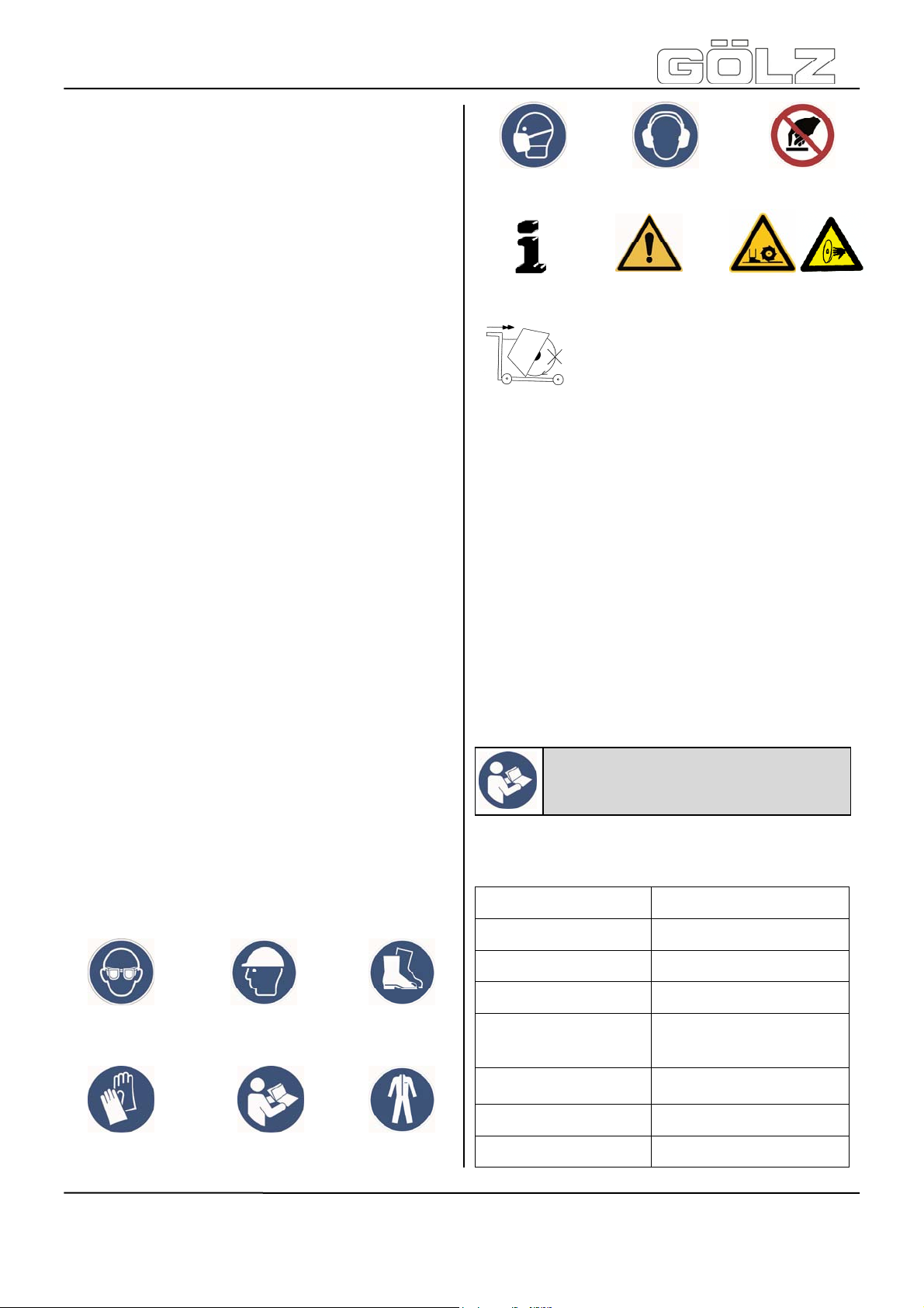
Never touch!
Danger exists
to cut oneself!
protection!
Important
advice!
Wear ear muffs! Wear dust
General danger!
It is not allowed to move the machine
with rotating blade outside of the area in
which cutting works have to be
erformed!
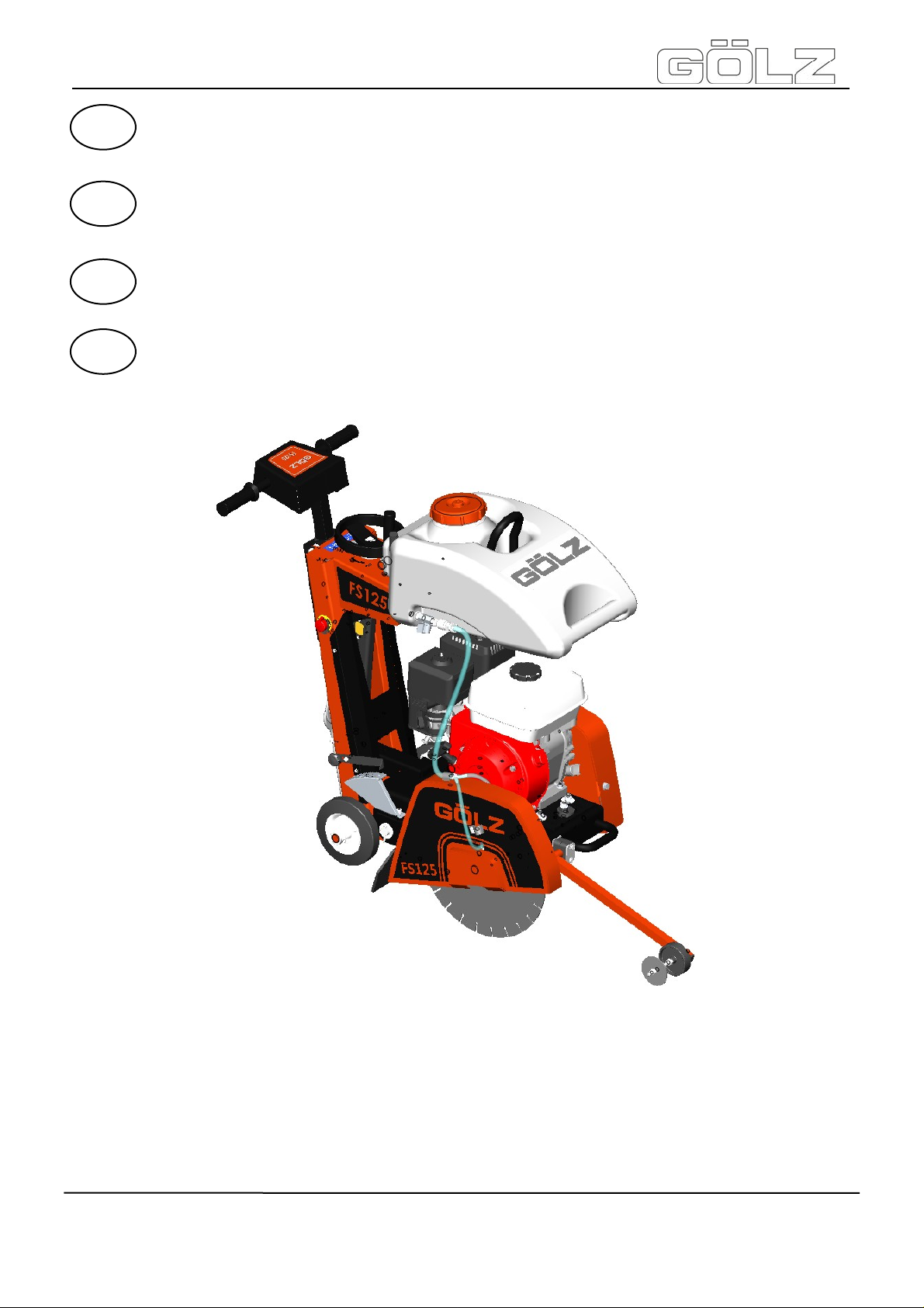
1. Machine description
1.1 Intended use-description
The FS 125 is a floor saw with a cutting depth of up to
120 mm.
Its operating range includes the concrete and asphalt
road construction, but mainly for transverse,
longitudinal and expansion joints.
Operate the machine only using tools in accordance
with the manufacturer’s instruction. Using other tools is
considered contrary to its designated use. The
manufacturer cannot be held liable for any damage
ulting from such use. The risk of such misuse lies
res
entirely with the user. The FS 125 is equipped with
a petrol Robin/Subaru or Honda engine and should
be operated with fuel specified by the manufacturer.
Information: Unconditional observe
the owner’s manual of the engine
manufacturer, which is added!
1.2 Technical data
Warning signs and symbols
Wear safety
glasses!
Wear protective
gloves!
Wear hard
hat!
Read owner’s manual
before first initiation!
Wear safety
boots!
Wear safety
clothes!
Max. cutting depth 120 mm - 4.7 in.
Max. blade-Ø 350 mm - 13.8 in.
Flange size Ø 90 mm - 3.54 in.
Blade shaft size Ø 25,4 mm - 1 in.
Petrol engine
Engine
Max. cutting speed with
blade
Engine shaft speed 3600 rpm
Blade shaft speed 2730 rpm
- 22-
Robin/Subaru
or HONDA
58,5 m/s - 192 ft./sec.
BA-DE-GB-FR-NL (001)
5009002-00
Page 8

FS125
Feed Manually
Cutting depth control
Manual with hand wheel
®
9
4
Cutting depth gauge
Water supply
V-belt tension Manually
Dimensions (L x W x H)
Weight (without water
tank and blade)
Sound power level after
DIN ISO 6393
Sound pressure level
after DIN ISO 6393
Vibration
ISO 5349 VDMA
03/2006
Scale on frame
25l Water tank
for dry cutting blades
approx. 510 x 780 x 922
mm - 20 x 30.7 x 36.3 “
approx. 60 kg - 132.3 lbs.
No load =104 dB(A)
Full load =114 dB(A)
No load =88 dB(A)
Full load =98 dB(A)
a = 4,5 m/s²
1.3 Shipment and provided
accessory
Floor saw FS125 without blade
Wrench SW 30
Operating instruction and spare parts list floor saw
Operating instruction engine
For the item number of accessories, please refer to the
current catalogue of GÖLZ
If accessories are used which do not correspond to
®
GÖLZ
damage resulting hereof.
For details regarding the selection of the right GÖLZ
diamond blades, please refer to the current GÖLZ
catalogue for diamond tools.
specifications, no liability is assumed for any
®
®
®
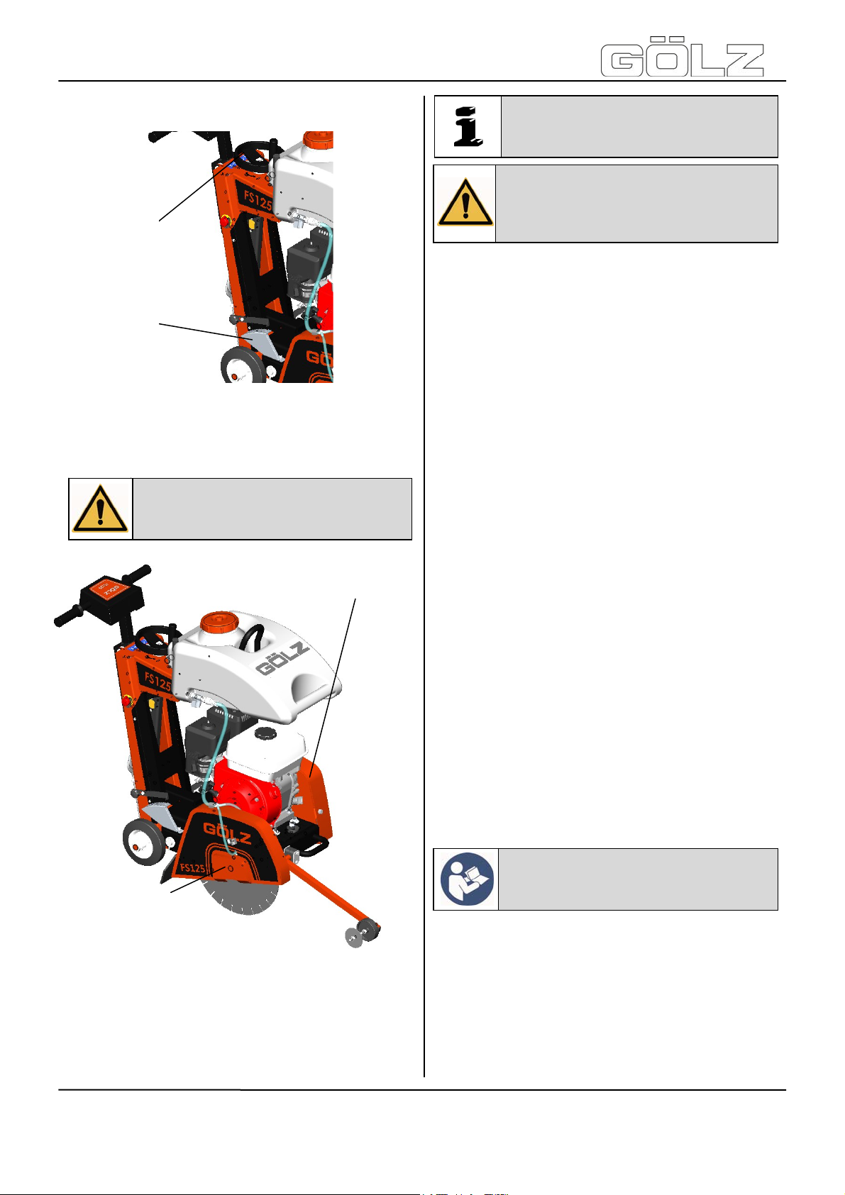
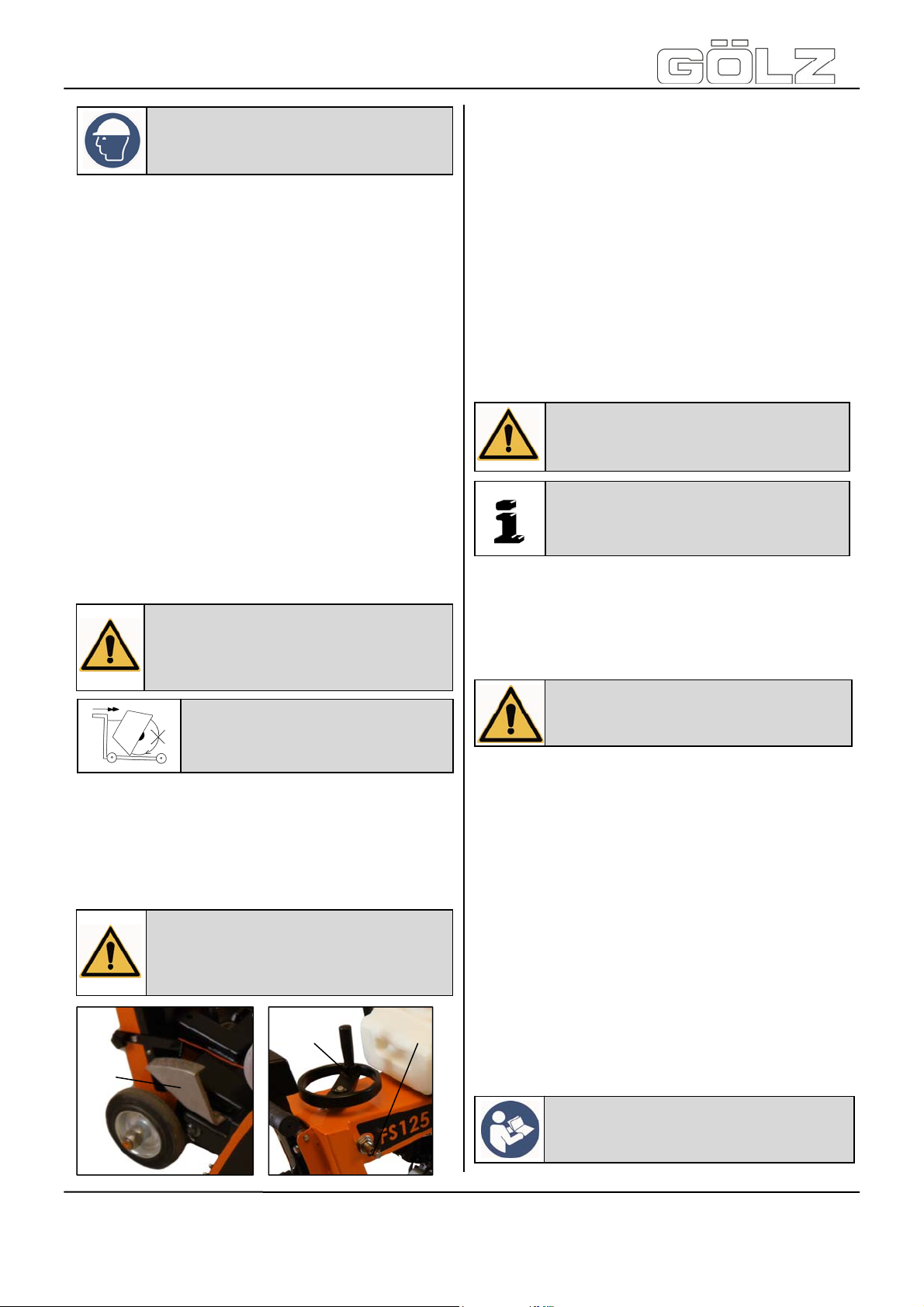
1.4 Main parts
1. Frame
2. Robin/Subaru or Honda Engine
3. Push bow
4. Water tank
5. Blade guard
6. Cutting depth indicator
7. Poly-V belt guard
8. Pointer unit
3
10
2
7
6
1
5
8
The base frame (1) is the basis for the floor saw. All
other components are built on the base frame.
The floor saw FS 125 is equipped with a petrol
engine (2) . For any other information, please refer to
the attached operating manual of the
engine manufac
The height adjustable push bar (3)
non-fatiguing working.
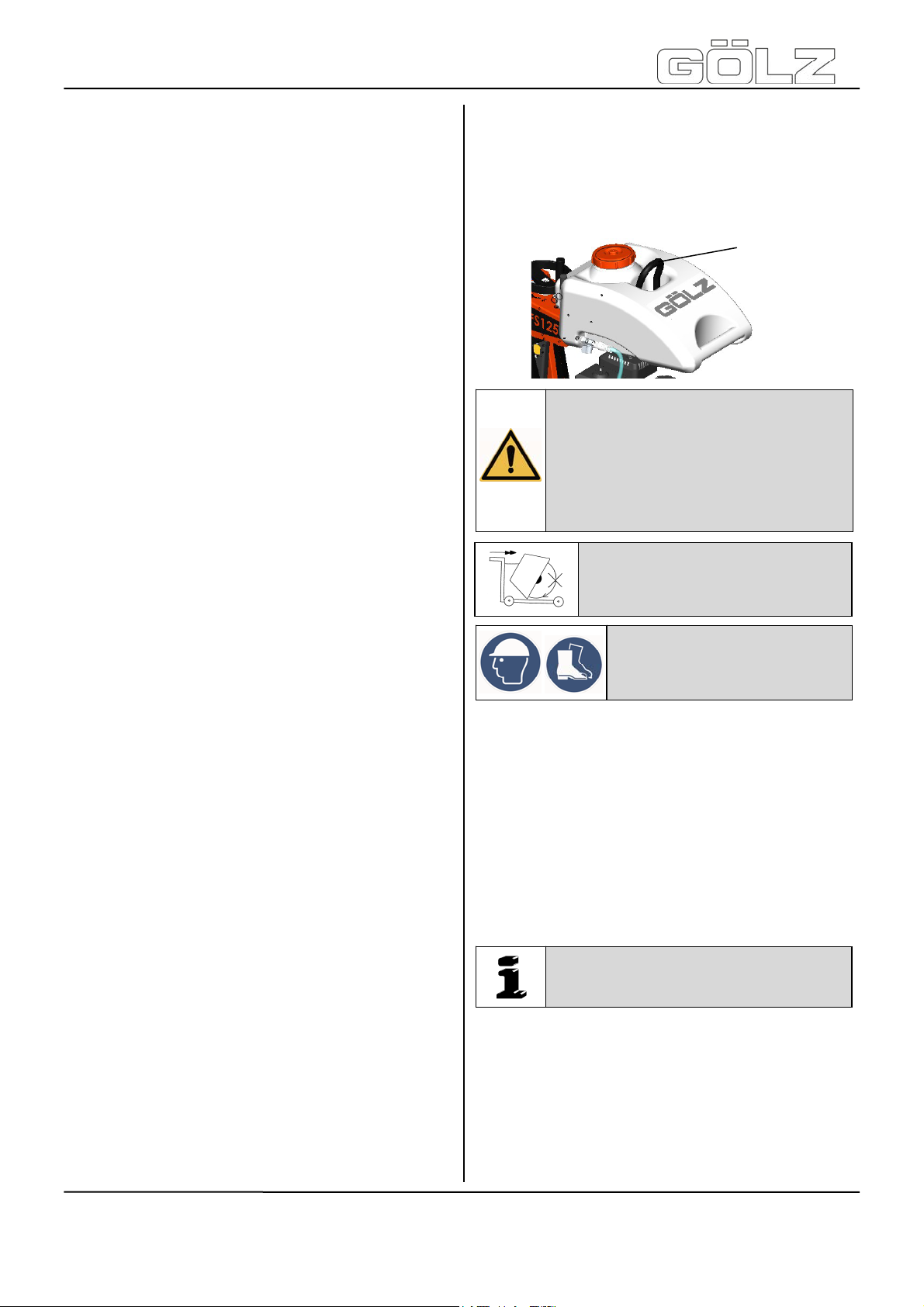
In order to allow dust formation during cutting
respectively cooling of the cutter blade, the floor saw is
equipped with a pluggable water tank (4).There is also
the possibility to cool directly by means of the water
s
upply network respectively to bind the dust.
The blade guard (5) provides the operator and the
persons in his working area with optimum protection
during the cutting process
By means of the convenient cutting depth setting (6),
the operator can read, at any time, the cutting depth.
The rib drive is protected by a poly
, the risk of injury is reduced by the rib drive.
Thus
Furthermore, the rib drive is also protected from
impurity during the cutting process.
The route indicator (8) allows precise cuts.
Thanks to the direction indicator the operator can
monitor and respect the cutting direction.
With suitable lifting gear the floor saw can be lifted
using the attached lifting eye (9) to facilitate transport.
Controlling the blade depth is by using by a hand
wheel (10) which is connected with a trapezoidal
spindle.
turer.
allows for
.
-V belt guard (7).
9. Lifting eye
10. Handwheel
- 23-
5009002-00
BA-DE-GB-FR-NL (001)
Page 9
FS125
®
1.5 Operating elements
1
2
1. Hand wheel - raising and lowering
2. Depth control
1.6 Safety devices
Danger: During cutting or displacing
the machine, all safety devices shown
below must be mounted!
Poly-V belt guard
Note / Important: Contains important
information which stands out from
the other text!
Attention: Contains instructions
which must be strictly observed to
prevent damage from the unit and the
operator!
Important text passages are highlighted in italics or
bold or can be found in a grey highlighted text field.
2.1 Intended use
The ma
of-the-art standards and the recognized safety rules.
Nevertheless, its use may constitute a risk to life and
limb of the user or of third parties, or cause damage to
the machine and to other material property.
The machine must only be used in technical perfect
condition in accordance with its designated use and
the instructions set out in the operating manual, and
only by safety-conscious persons who are fully aware
of the risks involved in operating the machine. Any
functional disorders, especially those affecting the
safety of the machine, should therefore be rectified
immediately!
The machine is designed exclusively for cutting in
concrete, reinforced concrete, natural stone, cast
stone and brickwork. Using the machine for purposes
other than mentioned above (such as cutting in wood
and so on) is considered contrary to its designated
use. The GÖLZ
damage resulting from such use. The risk of such
misuse lies entirely with the user.
Only use gear drives and motors, which are provided
by GÖLZ
manuals.
Operating the machine within the limits of its
designated use also involves observing the
instructions set out in the operating manual and
complying with the inspection and maintenance
directives.
chine has been built in accordance with state-
®
GmbH cannot be held liable for any
®
GmbH. Also attend those operating
Blade guard
2. Basic safety instructions
In this manu
used for particular important information:
al the following terms and symbols are
Attention: Read and observe all the
operating instructions which belong
to this unit!
2.2 Operating range
Do not modif
a way which could affect its safety and do not use nonofficial accessories! This is not allowed without prior
approval of GÖLZ
- 24-
y, add components to or retrofit the unit in
®
GmbH!
5009002-00
BA-DE-GB-FR-NL (001)
Page 10
FS125
2.3 Organisational measures
This op
place of use of the machine and must be accessible to
the person operating the machine!
In addition to this operating manual, all other generally
applicable legal and other mandatory regulations
relevant to accident prevention and environmental
protection must be observed! Such obligations may
also comprise the handling of hazardous materials,
provisioning and/ or wearing of personal protective
equipment, or road traffic regulations.
This operating manual must be supplemented by
instructions covering the duties involved in supervising
and notifying special organizational features, such as
job organization, work flows or the person entrusted
with the work. Person entrusted with work on the
machine must have read the operating manual prior to
taking up work. This applies especially to persons
working only occasionally on the machine, e.g. during
set-up or maintenance activities.
Check - at least from time to time - whether the
personnel is carrying out the work in compliance with
the operating manual and paying attention to risks and
safety-relevant factors.
For reasons of safety, long hair must be tied back or
otherwise secured, garments must be close-fitting and
no jewellery - including rings - may be worn.
Severe injury may result from being caught by moving
parts of the machine. Personal protective equipment
must be used wherever required by the circumstances
or by law (e.g. safety glasses, ear protectors, safety
boots, suitable safety clothing). Observe the
regulations for prevention of accidents! Observe all
safety precautions and warnings attached to the
machine and always keep them in good and perfectly
legible condition.
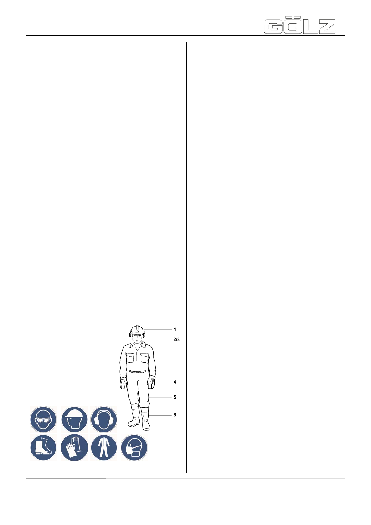
The personal protection equipment should consist
of the following parts:
erating manual must always be at hand at the
1) Hard hat with ear muff
2) Visor or safety glas
t
3) Dus
4) Protectiv
5) Safety c
6) Safety boots
mask
l
gloves
e
othes
ses
®
se event of safety-relevant modifications or
In ca
changes in the behaviour of the machine, stop the
machine immediately and report the malfunction to the
competent authority/ person. Do not remove or make
inoperative any safety devices the machine is
equipped with.
Never make any modifications, additions or
conversions which might affect safety without GÖLZ
GmbH prior approval! This also applies to the
installation and adjustment of safety devices as well as
to welding and cutting work on supporting structures.
Damaged or worn parts of the product must be
replaced immediately. Use genuine spare parts only.
All spare parts and tools must comply with the
technical requirements specified by the manufacturer/
distributor. Adhere to the legally prescribed preventive
maintenance and inspection intervals or those
specified in this operating manual!
Hydraulic hose pipes must be changed within the
specified or appropriate intervals, even if no safetyrelevant defects are visible.
All maintenance and repair activities must be
performed by qualified personnel using suitable tools
and other suitable workshop equipment. Observe the
fire alarm and fire fighting measures. The personnel
must be made familiar with the location and handling
of fire extinguishers!
®
2.4 Selection and qualification of
person
Only pe
with the machine! The legal minimum age is to be
observed!
Only assign trained and instructed personnel! Clearly
define the responsibilites of the personnel with regard
to operating, setting-up, maintaining and repairing the
machine! The GÖLZ
your personnel.
Make sure that only instructed and competent
personnel works on the machine. Define the
responsibility of the machine operator, also in terms of
traffic regulations and enable him to refuse instructions
of third parties which breach safety regulations.
Personnel that is to be trained or to be instructed or
that is serving a general training is only to be permitted
to operate the machine under the supervision of an
experienced person.
To operate the machine you must be rested, in good
physical condition and mental health. If you have any
condition that might be aggravated by strenuous work,
check with your doctor before operating with the
machine. Do not operate the machine if you are under
the influence of any substance (drugs, alcohol) which
might impair vision, dexterity or judgment.
Works on electrical, pneumatic, combustion and
hydraulic fittings and equipment are only to be carried
out by qualified personnel or instructed people being
rmitted personnel is allowed to work on and
®
GmbH can assist you in training
- 25-
5009002-00
BA-DE-GB-FR-NL (001)
Page 11

FS125
®
directed and supervised by qualified personnel in
compliance with the respective rules!
2.5 Safety instructions governing
specific operational phases
Bef
ore work
Avoid any operational mode that might be prejudicial to
safety!
Before beginning work, familiarize yourself with the
surroundings and circumstances of the site, such as
obstacles in the working and travelling area, the soil
bearing capacity and any barriers separating the
construction site from public roads.
Take the necessary precautions to ensure that the
machine is used only when in a safe and reliable state.
Operate the machine only if all protective and safetyoriented devices, such as removable safety devices,
emergency shut-off equipment, sound-proofing
elements and exhausters, are in place and fully
functional.
Regard all safety specifications!
Check the machine at least once per working shift for
obvious damage and defects. Report any changes
(incl. changes in the machine’s working behaviour) to
the competent organization/ person immediately. If
necessary, stop the machine immediately and lock it.
Have any defects rectified immediately. At any time,
ensure the operator has sufficient view to his working
area, in order to have intervention to the working
process.
Wet cutting is to be accomplished while working. This
prevents the appearance of particulate matter and
increases the life-time of the diamond tool. During
start-up and shut-down procedures always watch the
indicators in accordance with the operating
instructions!
Before starting or setting the machine in motion, make
sure that nobody is at risk. Keep children and
unauthorized persons away from the work area.
Noise protection equipment on the unit must be in
protective position during operation. Wear the required
individual ear protection!
Always keep at a distance from the edges of building
pits and slopes. Avoid any operation that might be a
risk to machine stability! Keep the work area clean.
Cluttered areas and benches invite injuries! Do not
operate when you are tired! Watch what you are doing!
Risk of stumbling! Cables and hoses must complete
rolling up. After assembly do not leave any tools, a
wrench for example, on the unit.
Check to see that the tools are removed from the
machine before operating! Damaged blades have to
be changed immediately. Use only recommended
blades from the GÖLZ
Control the working area for water-, gas- and electrical
lines!
®
GmbH.
Important: Wet cutting is to be
accomplished while working! This
prevents the appearance of particulate
matter and increases the life-time of
the diamond tool!
During work
Make sure, that the machine is well fastened before
and while cutting!
Never touch rotating parts like blade shaft or blade!
After work
Before leaving the machine always secure it against
unauthorized use!
2.6 Special work related to the
maintenance and repair of the
machine
Observe the
activities and intervals set out in the operating
instructions, including information on the replacement
of parts and equipment! These activities may be
executed by skilled personnel only.
Brief operating personnel before beginning special
operations or maintenance work, and appoint a person
to supervise the activities.
In any work concerning the operation, conversion or
adjustment of the machine and it’s safety-oriented
devices or any work related to maintenance, inspection
and repair, always observe the start-up and shut-down
procedures described in the operating instructions and
the information on maintenance work. Ensure that the
maintenance area is adequately secured.
Carry out maintenance and repair work only of the
machine is positioned on stable and level ground and
has been secured against inadvertent movement and
buckling. If the machine is completely shut down for
maintenance and repair work, it must be secured
against inadvertent starting.
To avoid the risk of accidents, individual parts and
large assemblies being moved for replacement
purposes should be carefully attached to lifting tackle
and secured. Use only suitable and technically perfect
lifting gear and suspension systems with adequate
lifting capacity. Never work or stand under suspended
loads.
The fastening of loads and the instructing of crane
operators should be entrusted to experienced persons
only. The marshaller giving the instructions must be
within sight or sound of the operator.
For carrying out overhead assembly work always use
specially designed or otherwise safety-oriented ladders
and working platforms. Never use machine parts as a
climbing aid. Wear safety harness when carrying out
maintenance work at greater heights.
adjustment, maintenance and inspection
- 26-
5009002-00
BA-DE-GB-FR-NL (001)
Page 12

FS125
®
Clean the machine, especially connections and
threaded unions, of any traces of oil, fuel or
preservatives before carrying out maintenance / repair.
Never use aggressive detergents. Use lint-free
cleaning rags.
Before cleaning the machine with water, steam jet or
detergents, cover or tape up all openings which -for
safety and functional reasons - must be protected
against water, steam or detergent penetration.
Do not clean the machine with a high-pressure
cleaner. The hard water jet can put damage to parts of
the machine. After cleaning, remove all covers and
tapes applied for that purpose.
After cleaning check the machine for loose
connections, chafe marks and damage! Have identified
defects repaired immediately!
Always tighten any screwed connections that have
been loosened during maintenance and repair.
Any safety devices removed for set-up, maintenance
or repair purposes must be refitted and checked
immediately upon completion of the maintenance and
repair work. Ensure that all consumables and replaced
parts are disposed of safely and with minimum
environmental impact.
2.7 Information about special risks
with electrical energy
The electrical equipment of machines is to be
inspected and checked at regular intervals. Defects
such as loose connections or scorched cables must be
rectified immediately.
Necessary work on live parts and elements must be
carried out only in the presence of a second person
who can cut off the power supply in case of danger by
actuating the emergency shut-off or main power
switch. Secure the working area with a red-and white
safety chain and a warning sign. Use insulated tools
only.
If mobile electrical equipment, connecting cables and/
or extension/ appliance cords with plug connectors are
used, ensure that such equipment, cables and cords
are checked for correct function at least once every six
months by a qualified electrician or - if suitable testing
equipment is available - by a properly instructed
person.
Protective installations with fault-current protection
units used in non-stationary equipment must be
checked for correct operation at least once a month by
a properly instructed person.
Fault-current and fault-voltage protection units must be
checked for correct operation by actuating the testing
facility:
once on every working day in the case
equipment,
at least once every six months in the case
stationa
ry equipment.
of mobile
of
Observe the
Electrical connections must always be kept free from
dirt and moisture.
Use only original fuses with the specified rating! Switch
off the machine immediately, if trouble occurs in the
electric power supply!
If your machine comes into contact with a live wire:
warn others against approaching and touching the
machin
have the live wire de-energized
When working with the machine, maintain a
ce from overhead electric lines. If work is to be
distan
carried out close to overhead lines, the workin
equipm
Caution, danger to life!
Check out the prescribed safety distances.
Work on the electrical system or equipment
only be ca
or by spe
control
accordance with the applicable engineering rules.
If provided for in the regulations, the po
to part
inspection, maintenance and repair wo
carried out must be cut off.
Before starting work, check the de-energized
parts for the presence of power and ground or
short-circuit them in addition to insulating adjacen
live parts an
relevant national regulations or standards.
e
ent must be kept well away
rried out by a skilled electrician hims
cially instructed personnel unde
and supervision of such electrician and in
s of machines and plants, on which
d elements.
from them.
safe
g
may
elf
r the
wer supply
rk is to be
2.8 Gas, dust, steam, smoke
Operate
rooms! Before starting the unit in closed rooms, make
sure that the room is sufficiently ventilated and use the
exhaust gas hose!
Welding, burning and grinding operations on the
machine are only to be carried out if this is explicitly
authorized (there is the danger of fire and explosion)!
Before welding, burning and grinding operations clean
the machine and its surrounding area from dust and
flammable substances and care for sufficient
ventilation (danger of explosion)!
When working in confined spaces observe any existing
national regulations!
combustion engines only in well-ventilated
2.9 Noise
Duri
ng operation sound protection devices on the
machine must be in safe position. Wear the prescribed
personal ear protection! (UVV 29 § 10, Article 29 of
the Accident Prevention regulations).
The use of noise emitting machines may be restricted
to certain times by national or local regulations.
t
- 27-
5009002-00
BA-DE-GB-FR-NL (001)
Page 13
FS125
®
2.10 Illumination
The ma
machine operator / owner must ensure sufficient
workplace lighting for non-illuminated work sites!
chine is designed for use in daylight! The
2.11 Oils, greases and other chemical
substances
Whe
n handling hydraulic fluids, lubricants, greases or
preservatives (referred to hereinafter as fuels and
lubricants), the safety regulations which apply to the
respective machine are to be observed!
Avoid long contact of the fuels and lubricants with your
skin! Careful cleaning of the skin from adhering fuels
and lubricants is necessary.
Be careful when handling hot consumables (risk of
burning or scalding) particularly at liquid temperatures
above 60°C, avoid any skin contact with these liquids!
If you get fuels or lubricants in your eyes, rinse them
immediately and carefully with potable water. Then
consult a doctor.
Remove flown out fuels and lubricants immediately!
Therefore use a binder.
Fuels and lubricants must not seep into the soil or into
the public sewage system! Fuels and lubricants which
can no longer be used are to be collected, properly
stored and to be properly disposed of.
The respective regulations and laws for handling fuels
and lubricants which are valid in the country of use are
to be observed and adhered to. This also applies to
the disposal of such fuels and lubricants. To inform
yourself turn to the responsible authorities.
the machine is used again!
Before setting the machine in motion always check
that all accessories are safely stowed.
The recommissioning procedure must be strictly in
accordance with the operating instruction! Observe the
instructions given in the operating instruction when
reassembling and operating the machine.
Lifting eye
Attention: Check that all parts of the
machine are well fastened before
transporting. Before transporting the
blade must be removed!
For loading, only use lifting gear and
tackle of sufficient capacity. Lift the
machine using the lifting eye.
During cuts displace the machine
only with non-rotating blade (not
running engine)!
Injury hazard: Down coming
parts!
2.13 Store
2.12 Transport
Use only
sufficient capacity when loading or transporting the
machine! Appoint an experienced instructor for the
lifting operation!
Always observe the instructions given in the operating
manual when lifting the machine (use only the
prescribed lifting eyes for attaching the lifting gear)!
Use only suitable transport vehicles with sufficient load
capacity! Secure the load carefully. Use suitable
fastening points for securing!
Before loading the machine or parts of it, secure the
machine against inadvertent movement! Attach a
suitable warning sign!
The blade must be removed for transport. Even in
case of a minor change of location, the engine must be
stopped!
Before using the machine again, make sure that such
protection material or devices are properly removed!
Parts which had to be removed for transporting of the
machine must be refitted and secured carefully before
suitable means of transport and lifting gear of
- 28-
Store the ma
the reach of children or unauthorized persons. Clean
and preserve the machine with corrosion preventive if
storing over a longer time like winter time!
Note: Store dismounted blades so, that the blades not
exposed to mechanical damages and harmful
environmental conditions (UV radiation, temperature,
humidity, etc.).
chine in a dry, high or locked place, out of
Attention: Store blades just standing
or hanging!
3. Preparing for Operation
3.1 Export checking
Remove
an environmentally responsible way. Check the
machine for completeness and intactness. For the
the transport packaging and dispose of it in
5009002-00
BA-DE-GB-FR-NL (001)
Page 14

FS125
g
®
scope of delivery, see "Scope of delivery and provided
accessory".
Secure the machine against accidental start-up and
rolling away.
Attention: Read and observe all
operating instructions which are
relevant for the machine (floor saw,
engine ...)!
The machine is not supplied with engine oil.
Attention: Before starting up, check
the engine oil level and fill up the fuel!
3.2 Installation
Place the machine on an even, firm and stable ground.
Have the working area well lightened. Keep the
working area clean, cluttered areas invite injuries.
Operating the machine on enclosed premises, make
sure that there is sufficient ventilation. Observe the
regulations in force at the respective site.
Note: If the oil level is too low, fill up
the engine according to the operating
manual of the engine manufacturer!
Fill up the fuel for the engine
according to the operating manual of
the en
ine manufacturer!
not leave any tools, such as open-end spanners, on
the machine.
Use only blades suitable to the blade acceptance
(arbor hole, flanges).
Danger: Faulty or damaged blades
can cause injuries to the operator and
other persons!
Information: Wrong rotation of the
blade will result in more wear of the
Danger: Wrong rotation of the blade
may result in segments cracking off
and can cause injuries to the operator
or other persons!
3.3.1 Mounting the blade
Blade mounting:
Mount the blade to the manufacturer’s odds
(Observe the min. flange-Ø; use only original
screws or nuts).
Use only blade diameters which are allowed
by the manufacturer.
Information: Clean all fastening
devices of the blade (flanges, thread
of the blade shaft, screws and nuts)
before mounting the blade!
3.3 Blade
The cutting discs must meet the specification of
®
GÖLZ
depending on the material to be processed, the
machining process and the type of work to be
performed! When not used properly, no liability is
assumed for damages resulting therefrom.
All used cutting discs must be designed, regarding
their maximum admissible cutting speed, for the max.
drive speed of the machine. For machines with
variable drive speed, use cutting discs which,
regarding their maximum admissible cutting speed,
correspond to the respective maximum drive speed of
the machine. Never use faulty or damaged blades.
Check the correct rotation of the blade to the spindle
shaft!
Check the blade is well fastened before beginning to
operate. Defective cutting discs must be replaced
immediately!
Cut off the engine or disconnect the power supply
before mounting or changing blade. After mounting, do
GmbH. Use the corresponding cutting discs
- 29-
SW30
Remove the cutting disc guard and unscrew the outer
clamping flange SW 30, left-hand thread.
All clamping surfaces must be clean and undamaged.
Fit the cutting disc. Pay attention to the correct
direction of rotation!
Observe the direction of rotation arrows on the cutting
disc and the cutting disc guard.
Mount the outer clamping flange again, fit the cutting
disc guard and secure it with the screw.
Danger: It is not allowed to operate the
machine without cutting disc blade
guard!
5009002-00
BA-DE-GB-FR-NL (001)
Page 15
FS125
®
3.4 Water supply
Important: The operation is to be
carried out in wet cutting, in order to
prevent the occurrence of harmful
particulate matter and to increase the
lifetime of the cutting tool.
Attention: Tools which are only
designed for wet cutting technique,
must never be used without water
supply! Always make sure that there is
enough water supply!
The supply of
cooled, the dust of the material is bound and the cut is
rinsed out.
water at the cut ensures that the tool is
Attention: Use only water for cutting
which is free from coarse impurities!
Do not use salt water!
Danger: Do run out of water in the water
tank when cutting with wet cutting
diamond blades. The segments may
crack off and cause injuries to the
operator or bystanders!
4. Operation
Information: Unconditional observe
the owner’s manual of the engine
Danger: Never touch rotating parts
like blade shaft or blade while
operating!
4.1 Before starting the machine
Chec
k the machine for safe operating condition.
All components must be properly mounted.
The functions of the combustion engine must
function prop
Do not make any changes on operating
elements and safety devices.
erly.
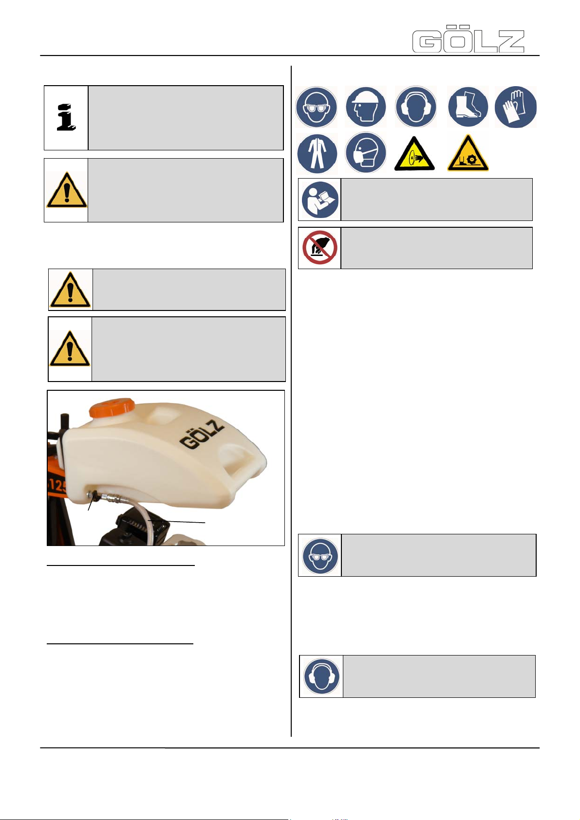
2
Cutting with wet-cutting blades:
Connect the detachable water hose with an external
water supply. Check the ball valve (2) is closed (ball
valve lever in 90°-position to the water flow).
For cutting open the ball valve (2) (ball valve lever in
the water flow position).
Cutting with dry-cutting blades:
Fill the water tank with clean water. Check the ball
valve (1) is closed (ball valve lever in 90°-position to
the water flow).
For cutting open the ball valve (1) (ball valve lever in
the water flow position).
The machine may only be operated in safe operating
condition.
Lock the push bars so that the machine can be
operated in a favorable posture.
If work is carried out where harmful or explosive
substances, such as dust, sludge occur, observe the
applicable national regulations.
If there is a risk that, during the cutting process,
material particles are accelerated outwards, wear
safety goggles.
Danger: Demolition parts can cause
injuries to the operator while cutting!
When travelling on public roads, ways and places
s
alway
necessary, make sure beforehand that the machine is
in a condition compatible with these regulations.
After operating secure the machine against
unintentional moving.
Appropriate to the application of the machine it could
be ne
observe the valid traffic regulations and, if
Danger: The sound pressure may
exceed 85 dB(A)!
ce
ssary to wear further protective equipment.
- 30-
5009002-00
BA-DE-GB-FR-NL (001)
Page 16
FS125
Danger: Down coming parts at the
building site can cause injuries to the
The working area is reserved only for the operator.
Keep unauthorized persons out of the working area.
Make sure the operator always has well sight to the
working area. He always has to intervene in the
working process. Never operate the machine without
mounted safety devices.
Careless handling can lead to life-threatening injuries
caused by the rotating cutting disc. Only operate the
machine with fully mounted blade guard.
Nobody is allowed to remain in the working area nor in
the area where falling segments of the cutting disc can
be accelerated outwards (minimum safety distance
10m). If this safety distance cannot be respected, the
danger zone must be closed or be marked by warning
signs.
Care for the whereabouts of cooling and rinsing water
as well as of cutting sludge.
Cutting sludge must be collected, filtered and disposed
of.
®
nect the water supply and slowly lower the
Con
machine with the hand wheel (1) till the blade has
ground contact. Putting down the machine to the
desired cutting depth which is displaying on the cutting
depth indicator (2).
Before you lower the machine by means of the hand
wheel (1), the mini ball valve is to be opened. Lower
the machine to such extent that you reach the desired
cutting depth (2).
Pull then the indexing plunger (3) on the control panel,
so that it snaps into the catch disk in order to fix the
desired cutting depth.
Work with even feed pressure. Too high feed pressure
leads to overload of the engine, there is a risk that the
machine raises. Too low feed pressure polishes the
segments and they become blunt.
Attention: In order to avoid damage to
the machine and the cutting disc, please
observe the maximum cutting depth!
Note: Do not lower the cutting disc
forcibly, this could lead to damage to
the cutting disc and to the machine.
4.2 Starting the machine
Danger: As soon as the combustion
engine is started, the cutting shaft,
respectively the cutting disc, starts
rotating too!
During cuts displace the machine
only with non-rotating blade (not
running engine)!
Compl
etely rise the machine (blade may have no
ground contact). Start the engine as described in the
engines manual.
4.3 Cutting operation
Danger: Operating with too high feed the
machine might rise out of cut! In
emergency situations cut off the engine
as described in the engines manual!
1
3
4.4 Stop cutting operation
After cutting compl
the engine as described in the engines manual.
Danger: Some parts of the
combustion engine become very hot
during operation, risk of burns!
etely raise the machine and cut off
4.5 Changing the blade
The blade must be changed if:
the diamond segments of the blad
completely worn
the material to be cut chan
the blade turns irregularly
the diamond segments are damaged or broken
For fitting a new blade, proceed as described in the
chapter "Mounting the blade".
ges
e are
5. Maintenance
2
5.1 General
Information: Unconditional observe
the owner’s manual of the engine
manufacturer, which is added!
- 31-
5009002-00
BA-DE-GB-FR-NL (001)
Page 17
FS125
®
Information: Clean the machine after
every operation. Observe local
environmental regulations!
Attention: When handling oil, grease
and other chemical substances,
observe the product-related safety
regulations!
For m
aintenance jobs the machine has to be shut
down. For maintenance jobs which must be done while
the machine is running, the blade has to be
dismounted before beginning the job.
In accordance to the given cycles, the subsequently
described maintenance work has to be enforced. Also
the wearing part subject to no certain maintenanceintervals has to be checked regularly for wear and to
adjust if necessary or to exchange. With I.C. engines,
the maintenance work has to be enforced in
accordance with the separate maintenance-instruction
of the engine manufacturer.
5.3 Poly-V belt
Unscrew the s
DIN EN ISO 4017) and the screw that fixes the
eccentric. Move the motor forwards by turning the
eccentric counter clockwise. In this position the poly-V
belt can be replaced easily.
Tension the poly-V belt by turning eccentric
clockwise. To fix the motor, screw down the M10x30
screws.
crews that fix the motor (4x M10x30,
5.4 Machine
Clean the machine after each use and check all
functions. Replace all necessary parts that are out
of order or worn out immediately.
5.5 Blade
When finishing a cutting job - check blade
as follows:
Check segments for cracks or break-outs,
Cracks between segment and core barrel,
Deformation and out of round wear.
In case of doubt, send the blade for repair.
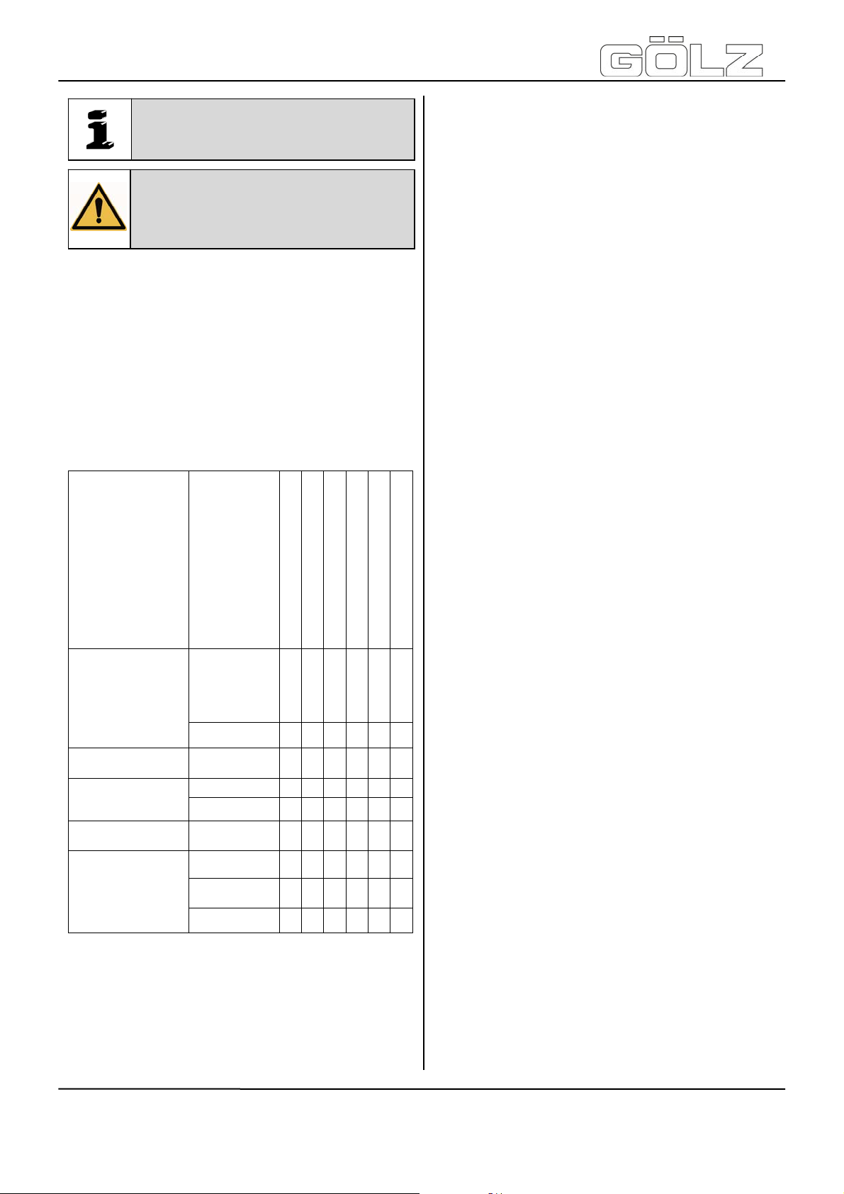
Visual
inspection
Complete
machine
Flange and blade
holder
Poly-V belt
Water nozzle and
feeding hoses
Tools
(condition,
absence of
leaks)
clean
clean
check
replace
clean
check
clean
replace
5.2 Lubricating chart
Before starting work
After work
Weekly
Yearly
In the event of a malfunction
If damaged
X X X
X
X
X X X X
X
X
X X
X
X
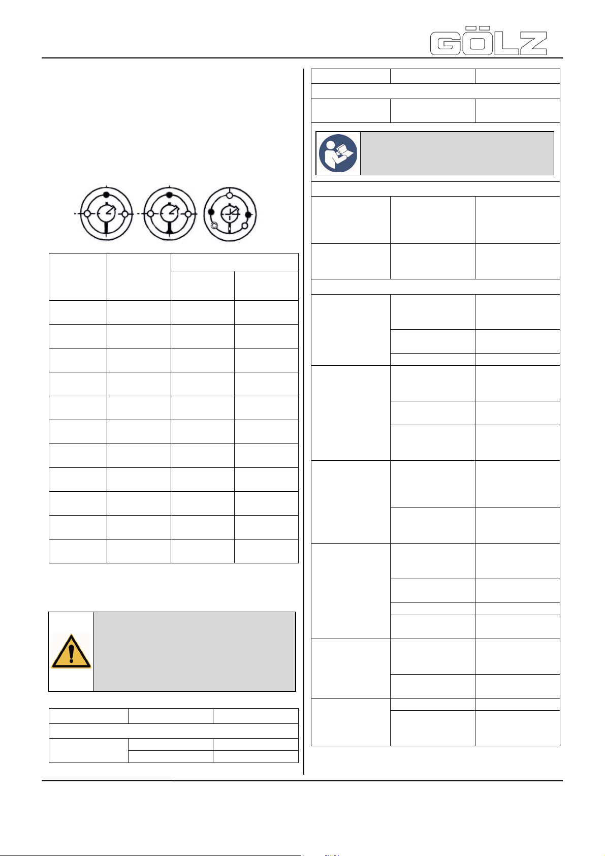
6. Taper bushes installation
instructions
6.1 To assemble
Clean and de-grease the bore and taper surfaces of
the bush and the tapered bore of the pulley. Insert the
bush in the pulley hub and line up the holes (half
thread holes must line up with half straight holes).
Lightly oil the grub screws or the cap screws and
screw them in, do not tighten yet.
Clean and de-grease the shaft. Fit pulley with taper
bush on shaft and locate in desired position.
When using a key it should first be fitted in the shaft
Keyway. There should be a top clearance between the
key and the keyway in the bore.
Using a hexagon socket wrench gradually tighten the
grub/cap screws in accordance with the torques as
listed in the schedule of screw tightening torques.
When the drive has been operating under load for a
short period (half to one hour) check and ensure that
the screws remain at the appropriate tightening torque.
In order to eliminate the ingress of dirt fill all empty
holes with grease.
Grease the blade s
haft bearings after 20
working hours with heat resistance grease. From
time to time clean the foot pedal, pointer unit and
wheels and grease them with some drops of oil.
- 32-
5009002-00
BA-DE-GB-FR-NL (001)
Page 18
FS125
®
6.2 Removal
Slacken all scre
remove one or two. After oiling point and thread of
grub screws or under head and thread of cap screws,
insert them into the jacking off holie(s) in bush.
Tighten screw (s) uniformly and alter neatly until the
bush is loose in the hub and pulley is free on the shaft.
Remove pulley bush assembly from shaft.
Bush
1008
1108
1310
1315
1210
1215
1610
1615
2012 31 2
2517 48 2
3020
3030
3535 112 3
4040 170 3
4545 192 3
5050 271 3
ws. Depending on the size of the bush
Scre
w
tightening
torques
(Nm)
5.6 2
20 2
20 2
20 2
90 2
Quantity Size
Screw
1/4“
BSW
3/8“
BSW
3/8“
BSW
3/8“
BSW
7/16“
BSW
1/2“
BSW
5/8“
BSW
1/2“
BSW
5/8“
BSW
3/4“
BSW
7/8“
BSW
7. Troubleshooting
Attention: In the event of changes in
the behaviour of the machine during
operation, stop the machine
immediately and report the
malfunction to the competent
authority/person!
Problem Cause
Engine does
not start!
Fuel tank empty Fill up
Dirty fuel lines Clean
Remedy
Engine
Problem Cause
Bad engine
performance!
Machine
lowers without
actuating the
foot pedal!
Machine does
not fully lower!
Machine rises
out of cut!
Non circular
abrasion
of the diamond
blade!
Diamond blade
jams
in the cut!
Abnormal
wear-out of
segments!
Abnormal
blade wear out
at sides of
core!
Bad cutting
performance!
Dirty air cleaner Clean
Note: For more fault finding refer the
operating instruction of the engine
manufacturer which is enclosed!
Lowering
APPLICABLE
APPLICABLE
Dull diamond
blade
Faulty gas
pressure spring
Feed too high Reduce feed
Damaged
centring of the
blade shaft
Warped blade
shaft
Loose or
damaged blade
shaft bearings
No free cut
because of sidewards wear-out
of segments
Damaged
diamond blade
core
Insufficient water
flow
Wrong type of
diamond blade
Feed too high Reduce feed
Cutting in loose
underground
Insufficient water
flow
Cutting in loose
underground
Slippy V-belts Adjust
Blunt diamond
blade
Remedy
Engine
NOT
NOT
Cutting
Sharpen or use
softer diamond
blade
Replace
Replace blade
shaft
Replace
Tighten or
replace
Replace diamond
blade
Replace diamond
blade
Check hoses for
fracture free
laying
Choose different
diamond blade
Reduce cutting
depth
Check hoses for
fracture free
laying
Reduce cutting
depth
Sharpen or use
softer diamond
blade
- 33-
5009002-00
BA-DE-GB-FR-NL (001)
Page 19

®
FS125
8. Ersatzteilliste / Spare parts list / Liste de pièces de rechange /
Reservedelenlijst
8.1 Verwendung der Ersatzteilliste / Using the spare parts list / Utilisation de la
liste des pièces de rechange / Gebruik van de lijst van reserveonderdelen
Die Ersatzteilliste ist keine Montage- oder Demontageanleitung. Diese Ersatzteilliste dient ausschließlich zum
einfachen und schnellen finden von Ersatzteilen, die bei de n Vertriebsstel le n, siehe Ka pitel 8.1.3 “Vertrie bsstellen“,
bestellt werden können.
The spare parts list is not a mounting or di smounting instruction. The only purpose of the spare parts list is to
easily and quickly find spare parts which can be ord ered with distributio n agencies, see chapter 8.1.3 "Distribution
agencies".
La liste des pièces de rechange n'est pas une notice de montage ou de démontage. Cette liste des pièces de
rechange sert exclusivement à trouver rapidement et facilement des pièces de rechange qui peuvent être
commandées aux points de vente, voir chapitre 8.1.3 "Points de Vente".
De lijst van reserveonderdelen is geen montage- of demontagehandleiding. De lijst van reserveonderdelen dient
uitsluitend voor het eenvoudig en snel terugvinden van reserveonderdelen, die je kan bestellen bij de distributiehandelaars, zie hoofdstuk 8.1.3 “distributiehandelaars“.
8.1.1 Sicherheitsvorschrift / Safety regulation / Consigne de sécurité / Veiligheidsvoorschrift
Gefahr: Montieren oder demontieren von Baugruppen können Risiken hervorrufen, auf die in
dieser Ersatzteilliste nicht hingewiesen wird!
Das Verwenden dieser Ersatzteilliste für Montage- oder Demontagezwecke ist nicht erlaubt. Für Montage und
Demontagearbeiten sind ausschließlich die entsprechenden Beschrei bungen in der Betriebsanleitung zu befolgen.
Gefahr: Nichtbeachten dieser Vorschrift, kann zu Verletzungen führen, die im schlimmsten
Fall auch den Tod zu Folge haben könnten!
Danger: Mounting or dismounting assembly groups can give rise to risks which are not
mentioned in the spare parts list!
Using this spare parts list for mounting or dismounting purposes is not permitted. For assembly and disassembly
work exclusively the corresponding descriptions in this operating manual are to be followed.
Danger: Non-observance of this instruction can result in in jury which, in the worst case, can
result in death!
Danger: monter ou démonter des modules de construction peuvent être à l'origine de
risques qui ne sont pas mentionnés dans cette liste des pièces de rechan g e!
Pour le montage ou le démontage, l'utilisation de cette liste de pièces de rechan ge n'est pas autorisée. Pour les
travaux de montage et de démontage, su ivre exclusivement les descriptions correspondantes indiquées dans le
mode d'emploi.
Danger: Le non-respect de cette instruction peut entraîner des blessures qui, dans le pire
des cas, peuvent entraîner la mort!
- 60-
5009002-00
BA-DE-GB-FR-NL (001)
Page 20

FS125
8.1.3 Vertriebsstellen / Distribution agencies / Points de Vente / Distributiehandelaars
Deutschland - Germany - Allemagne - Duitsland
GÖLZ
Dommersbach 51
DE-53940 Hellenthal
Tel: +49 (0)2482-12 200
Fax: +49 (0)2482-12 222
E-Mail: info@goelz.de / Internet: www.goelz.de
Österreich - Austria - Autriche - Oostenrijk
GÖLZ
Samstraße 52
A-5020 Salzburg
Tel: +43 (0) 662 - 43 81 75
Fax: +43 (0) 662 - 43 07 34
E-Mail: info@goelz.at / Internet: www.goelz.at
Großbritannien - Great Britain - Grande-Bretagne Groot-Brittannië
GÖLZ
Unit A5, Springhead, Enterprise Park
Northfleet
Kent DA11 8HB
Tel: +44 1 474321679
Fax: +44 1 474321477
E-Mail: info@goelz.co.uk / Internet: www.goelz.co.uk
Australien - Australia - Australie - Australië
GOLZ
44 Stanley Street
Peakhurst, NSW 2210
Tel: +61 (0) 2 9534 5599
Fax: +61 (0) 2 9534 5588
E-mail: info@golz.com.au / Internet: www.golz.com.au
8.1.2 Bestellangaben / Ordering information / Indications de commande /
Gevaar: Het monteren en demonteren van onderdelen kan risico’s met zich meebrengen,
waarnaar niet wordt verwezen in de lijst van reserveonderdelen!
Het is niet toegestaan deze lijst van reserveonderdelen voor montage- of demo ntage doeleinden te gebruiken.
Enkel de betreffende beschrijvingen in de gebruiksaanwijzing moeten opgevolgd worden voor montage- en
demontagewerkzaamheden.
®
GmbH
Gevaar: De niet naleving van deze voorschrift kan leiden tot kwetsuren, die in het ergste geval
de dood tot gevolg kunnen hebben.
®
Ges.m.b.H
Frankreich - France - France - Frankrijk
®
GÖLZ
S.A.S.
1, rue de la Mairie
F-67370 Berstett
Tel: +33 (0)3.88.59.43.00
Fax: +33 (0)3.88.59.47.77
E-Mail: info@golz.fr / Internet: www.golz.fr
Benelux
®
(UK) Ltd.
GÖLZ® Benelux
Eupener Straße 61
BE-4731 Raeren-Eynatten
Tel: +49 (0)2482-12 200
Fax: +49 (0)2482-12 222
E-Mail: benelux@goelz.de / Internet: www.goelz-online.com
®
Pty Ltd.
USA
GOLZ
®
L.L.C.
5860 East Osage Ridge Lane
Columbia MO 65203-6018
Tel: +1 573 474 4961
E-Mail: info@golzusa.com / Internet: www.goelz-online.com
Bestellingaanduidingen
Hinweis: Um Falschlieferungen zu vermeiden sollten vor der Versendung die Angaben in der
Bestellung auf Richtigkeit und Vollständigkeit überprüft werden! Lieferadresse vollständig
angeben!
Note: In order to avoid wrong deliveries the information the ordering information should be
checked for accuracy and completeness before s ending it! Completely indicate the delivery
address!
®
- 61-
5009002-00
BA-DE-GB-FR-NL (001)
Page 21
FS125
Notice: Afin d'éviter des livraisons incorrectes, vérifier, avant l'envoi de la livraison, si les
indications de commande sont correctes et complètes! Indiquer l'adresse complète de la
livraison!
Gevaar: Om foute leveringen te vermijden dienen voor de verzending de aanduidingen op de
bestelling op juistheid en volledigheid te worden gecontroleerd! Het leveradres volledig
vermelden!
®
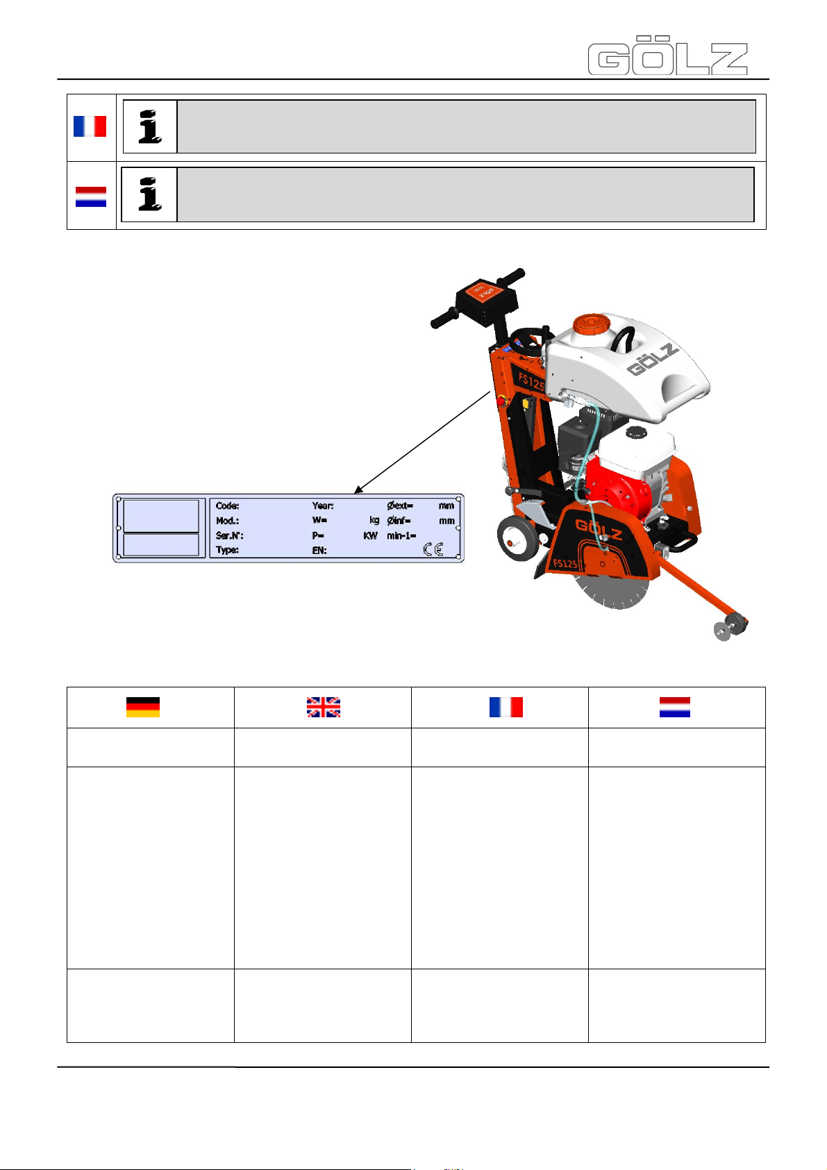
So bekommen Sie schnell
und richtig Ihr Ersatzteil
Maschinentyp gemäß
Typenschild
Baujahr gemäß
Typenschild
Artikelnummer gemäß
Ersatzteilliste
Maschinennummer
gemäß Typenschild
Für Bestellungen, Fragen und
Informationen wenden Sie sich
bitte an die zuständigen
Stellen.
Always indicate
machine type according to
nameplate
year of manufacture
according to nameplate
order number according to
spare part list
serial number according to
nameplate
For orders, questions and
information, please contact the
competent departments.
Pour obtenir rapidement les
pièces de rechange indiquer
type de la machine con-
forme de plaque d'identification
Année de construction se-
lon plaque d'identification
Numéro de l'article selon la
liste des pièces de rechange
numéro de la machine con-
forme de plaque d'identification
Pour les commandes, questions
et informations, veuillez-vous
adresser aux points de ventes
correspondants.
- 62-
Zo ontvangt u snel uw juiste
reserveonderdelen
Machinetype volgens
identificatieplaatje
Bouwjaar volgens
identificatieplaatj
Artikelnummer volgens lijst
van reserveonderdelen
Machinenummer volgens
identificatieplaatje
Voor bestellingen, vragen of
informatie kan u steeds terecht
bij de verschillende
handelaars.
5009002-00
BA-DE-GB-FR-NL (001)
Page 22

FS125
8.2 Verschleißteile / Wearing parts / Pièces d’usure / Slijtdelen
®
Verschleißteile für die in der Bedienungsanleitung erwähnten Maschinen wie Kernbohrgeräte, Fugenschneider, Wandsägen und
Tischkreissägen.
Verschleißteile sind Teile, die bei bestimmungsgemäßem Gebrauch der Maschinen einer betriebsbedingten Abnutzung unterliegen. Die Verschleißzeit
ist nicht einheitlich definierbar, sie differiert nach der
Einsatzintensität. Die Verschleißteile sind gerätespezifisch entsprechend der Betriebsanleitung des
Herstellers zu warten, einzustellen und ggf. auszutauschen. Ein betriebsbedingter Verschleiß bedingt
keine Mängelansprüche.
Verschleißteile sind in der Ersatzteilliste grau
unterlegt!
Vorschub- und Antriebselemente wie Zahnstangen,
Zahnräder, Ritzel, Spindeln, Spindelmuttern, Spindellager, Seile, Ketten, Kettenräder, Riemen
Dichtungen, Kabel, Schläuche, Manschetten, Stecker,
Kupplungen und Schalter für Pneumatik, Hydraulik,
Wasser, Elektrik, Kraftstoff
Führungselemente wie Führungsleisten, Führungs-
buchsen, Führungsschienen, Rollen, Lager, Gleitschutzauflagen
Spannelemente von Schnelltrennsystemen
Spülkopfdichtungen
Gleit- und Wälzlager, die nicht im Ölbad laufen
Wellendichtringe und Dichtelemente
Reib- und Überlastkupplungen, Bremsvorrichtungen
Kohlebürsten, Kollektoren
Leichtlöseringe
Regelpotentiometer und manuelle Schaltelemente
Sicherungen und Leuchten
Hilfs- und Betriebsstoffe
Befestigungselemente wie Dübel, Anker und
Schrauben
Bowdenzüge
Lamellen
Membranen
Zündkerzen, Glühkerzen
Teile des Reversierstarters wie Anwerfseil, Anwerf-
klinke, Anwerfrolle, Anwerffeder
Abdichtbürsten, Dichtgummi, Spritzschutzlappen
Filter aller Art
Antriebs-, Umlenkrollen und Bandagen
Seilschlagschutzelemente
Lauf- und Antriebsräder
Wasserpumpen
Schnittguttransportrollen
Bohr-, Trenn- und Schneidwerkzeuge
Energiespeicher
Wearing parts for construction devices
mentioned in the operating manual such as
drilling and sawing machines.
Wearing parts are the parts subject to operationrelated (natural) wear during proper use of the device.
The wearing time cannot be uniformly defined, and
differs according to the intensity of use. The wearing
parts must be adjusted, maintained and, if necessary,
replaced for the specific device in accordance with the
manufacturer’s operating manual. Operation-related
wear is not a reason for defect claims.
Wearing parts of this machine are grey
marked in the spare parts list.
Feed and drive elements such as toothed racks,
gearwheels, pinions, spindles, spindle nuts, spindle
bearings, cables, chains, sprockets, belts
Seals, cables, hoses, packings, connectors, couplings
and switches for pneumatic, hydraulic, water, electrical
and fuel systems
Guide elements such as guide strips, guide bushes,
guide rails, rollers, bearings, sliding
protection supports
Clamping elements for quick-separating systems
Flushing head seals
Slide and roller bearings that do not run in an oil bath
Shaft oil seals and sealing elements
Friction and safety clutches, braking devices
Carbon brushes, commutators / armatures
Easy-release rings
Control potentiometers and manual switching elements
Securing elements such as plugs, anc hors, screws and
bolts
Fuses and lamps
Auxiliary and operating materials
Bowden cables
Discs
Diaphragms
Spark plugs, glow plugs
Parts of the reversing starter such as the starting rope,
starting pawl, starting roller and
starting spring
Sealing brushes, rubber seals, splash protection cloths
Filters of all kinds
Drive rollers, deflection rollers and bandages
Cable anti-twist elements
Running and drive wheels
Water pumps
Cut-material transport rollers
Drilling, parting and cutting tools
Energy storage
- 63-
5009002-00
BA-DE-GB-FR-NL (001)
Page 23

FS125
Pièces d’usure définies dans la notice
d’utilisation pour les machines telles que
carotteuses, scies à sol, scies murales et
scies de tables.
Les pièces d’usure sont celles définies par une usure
normale due à I’utilisation courante de la machine
dans les conditions normales d’utilisation. La durée
d’usure n’est pas définissable en terme de temps,
elle dépend de I’intensité d’utilisation. Les pièces
d’usure sont à régler ou changer selon les indications
définies dans la notice d’utilisation par le fabricant de
la machine. Une usure normale due à I’utilisation de
la machine ne peut faire prétendre à une demande
de garantie
Des pièces d'usure pour cet appareil sont
soutenues gris dans le catalogue pièces
Éléments d’entraînement, d’avance tels que
crémaillères, pignons, vis sans fin écrous pour vis sans
fin, roulements de vis, câbles, chaînes, pignons de
chaîne, courroies
Joints, câbles électriques, flexibles, manchettes, prises
de courant, accouplements et éléments de commande
pneumatiques, hydrauliques, pour eau et carburant
Éléments de guidage tels que glissières, douilles de
guidage, rails de guidage, galets de guidage,
roulements, protections de guidage
Éléments de serrage pour systèmes d’accouplements
rapides
Joints de touret d’injection
Roulements à aiguilles et linéaires non en bain d’huile
Joints spi et éléments d’étanchéité
Embrayage de surcharge systèmes de freinage
Charbons et collecteurs
Bagues à desserrage rapide
Potentiomètres et éléments de commandes manuelles
Fusibles et ampoules
Accessoires de fonctionnement
Éléments de fixation tels que chevilles, vis et vis
d’ancrage
Sandows
Lamelles
Membranes
Bougies d’allumage et de préchauffage
Pièces du système de démarrage, telles que poignée
de démarrage, poulie, ressort
Brosse joint, joints caoutchouc, bavettes anti-
éclaboussement
Filtres de tous types
Poulies d’entraînement ou de renvoi et leur bandage
Éléments anti-flottement de câbles
Roues d’entraînement et de guidage
Pompes à eau
Rouleau de convoyeurs
Outils de carottage et de sciage
Réservoir d’énergie
®
Slijtdelen voor de machines vermeld in de
handleiding zoals de kernboormachines,
voegensnijmachines, wandzagen en
tafelcirkelzagen.
Slijtdelen zijn die onderdelen die bij een correct
gebruik van de machine bedrijfsgerelateerde
onderhavig zijn aan slijtage. Slijtagedelen kunnen niet
uniform gedefinieerd worden, ze zijn anders
afhankelijk van de gebruiksintensiteit. Slijtdelen zijn
specifiek voor het toestel overeenkomstig de
handleiding van de leverancier te onderhouden, in te
stellen en indien nodig te vervangen.
Bedrijfsgerelateerde slijtage geeft geen recht op
garantie.
Slijtonderdelen zijn in de reservedelenlijst in
het grijs weergegeven!
Voedings- en aandrijv ingsonderdelen zoals tandstangen,
tandwielen, rondsels, spindels, spindelmoeren,
spindellagers, touwen, kettingen, kettingwielen, riemen
Dichtingen, kabels, slangen, manchetten, stekkers,
koppelingen en schakelaars voor de pneumatiek,
hydrauliek, water, elektriciteit, brandstof
Geleidingselementen zoals geleidingslijsten,
geleidingsbussen, rollen, lagers en antislipbeleggingen
Opspanelementen van scheidingssystemen
Dichtingen spoelkoppen
Glij- en rollagers, die niet door een oliebad lo pen
As-afdichtringen en dichtingselementen
Wrijvings- en overbelastingskoppeling, remm en
Koolborstels, collectoren
Ring voor snelle (de-)montage
Regelpotentiometer en manuele schakelelementen
Zekeringen en lampen
Hulp- en grondstoffen
Bevestigingselementen zoals wie doppen, ankers en
schroeven
Remkabels
Lamellen
Membranen
Ontstekingsbougies, gloeibougies
Onderdelen van de reservestarter zoals startkabel,
starrol, startveer
Afdichtingsborstels, dichtingsrubbers, spatlappen
Filters van allerlei aard
Aandrijvings-, omkeerrollen en bandages
Touwslagbeschermingselementen
Loop- en aandrijvingswielen
Waterpompen
Transportrollen materiaal
Boor-, scheidings- en snijwerktuigen
Energiebuffer
- 64-
5009002-00
BA-DE-GB-FR-NL (001)
Page 24
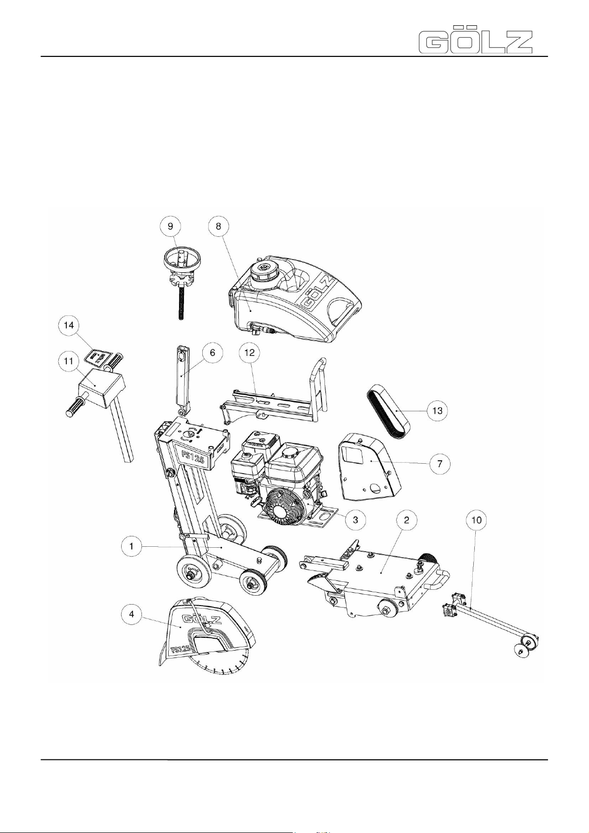
FS125
9. Explosionsansichten und Ersatzteillisten - Exploded view and spare
parts list - Vues éclatées et liste des pièces de rechange Explosietekeningen en lijst met reserveonderdelen
9.1 Maschine / Machine / Machine / Machine
®
- 65-
5009002-00
BA-DE-GB-FR-NL (001)
Page 25

®
FS125
Pos. Art.-Nr.
1 - 1
2 - 1
3 - 1
4 - 1 Ø350
5 - 1
6 - 1
7 - 1
8 0282 170 6160 1
9 - 1
10 - 1
11 - 1
12 - 1
13 0282 120 0561 1 12 PK605
14 - 1 Aufkleber Sticker Autocollant Sticker
Menge
Qty.
Norm Info Bezeichnung Description Désignation Benaming
siehe Seite
see page
regardez à la page
zie pagina
67
siehe Seite
see page
regardez à la page
zie pagina
71
siehe Seite
see page
regardez à la page
zie pagina
75
siehe Seite
see page
regardez à la page
zie pagina
73
siehe Seite
see page
regardez à la page
zie pagina
76
siehe Seite
see page
regardez à la page
zie pagina
77
siehe Seite
see page
regardez à la page
zie pagina
78
.
siehe Seite
see page
regardez à la page
zie pagina
79
siehe Seite
see page
regardez à la page
zie pagina
80
siehe Seite
see page
regardez à la page
zie pagina
81
siehe Seite
see page
regardez à la page
zie pagina
82
siehe Seite
see page
regardez à la page
zie pagina
85
Fahrwerk kpl.
Schneidkopf kpl.
Motor kpl. Motor complete
S-Haube kpl.
Aufnahme
Führungsstange
kpl.
Spindelaufnahme kpl.
Keilriemenschutzhaube
Wassertank
Kpl.
Tiefeneinstellung kpl.
Richtungsanzeigerkpl.
Schubstange
kpl.
Halterung
Transportöse
kpl.
Poly-V
Riemen
Under-carriage
complete
Cutter head
complete
Blade guard
complete
Receiving part
guiding rod
complete
Shaft support
complete
V-belt guard
Water Tank
complete
Depth
adjustment
complete
Pointer unit
complete
Push rod
complete
Lifting eye
holder complete
V - ripped belt
Châssis
complète
Couteau en-tête
complète
Moteur
complète
Capot de
Protection
compète
Support de
poignée
réglable
complète
Fixation de la
broche complet
Capot de
protection
Réservoir
d’eau complet
Système de
plongée complet
Indicateur de
direction
complète
Bielle compilation
complète
Crochet de
levage complet
V - déchiré
ceinture
Loopwerk
volledig
Zaagkop
volledig
Motor volledig
Bescherm-kap
Zaagblad
volledig
Opname
geleidingsstang
volledig
As opname
volledig
V snaren
beschermkap
Watertank,
volledig
Diepte instelling
volledig
Richtingsaanwijzer
volledig
Trekstang
volledig
Hijsoog
montage
volledig
Poly-V snaren
- 66-
5009002-00
BA-DE-GB-FR-NL (001)
Page 26

FS125
9.2 Fahrwerk - Undercarriage - Châssis - Loopwerk
®
- 67-
5009002-00
BA-DE-GB-FR-NL (001)
Page 27

®
FS125
Pos. Art.-Nr.
- - 1 Pos. 1-39 Fahrwerk kpl.
Pos. Art.-Nr.
1 - 1 Fahrgestell Undercarriage Châssis Loopwerk
2 - 1 Abdeckung Cover Coiffe Afdekking
3 - 1
4 - 2
5 - 2
6 - 1 FS125 Aufkleber Sticker Autocollant Sticker
7 - 1 Typenschild Name plate
8 0282 125 6103 1 Federriegel Spring latch
9 0282 175 6121 1 M6x16
10 0282 175 6123 2 20x23-20 Gleitlager Bush bearing
11 0282 017 9036 2 Ø125-Ø15x50 Rad Wheel Roue Wiel
Menge
Qty.
Menge
Qty.
Norm Info Bezeichnung Description Désignation Benaming
Under-carriage
complete
Norm Info Bezeichnung Description Désignation Benaming
Tiefenanzeiger
Werkzeughalter (klein)
Werkzeughalter (groß)
Sterngriffschraube
Depth finder
Tool holder
(small)
Tool holder
(big)
Star grip
screw
Châssis
complète
Indicateur de
la gravité
Porte-outil
Porte-outil
Plaque
signalétique
Verrous à
ressort
Poignée-étoile
Roulement
coulissant
Loopwerk
volledig
Diepteaanduider
Gereedschaphouder
Gereedschaphouder
Typeplaatje
Veerbout
Stergreep-
schroef
Glijlager
12 0282 125 6102 2 Ø160-Ø20x60 Hinterrad Back wheel Roue arrière Achterwiel
13 0295 000 2044 1
14 0295 000 2031 1
15 0295 000 2038 1
36100-ZH8-
16
17 - 2
18 2
19 - 1
20 - 3
21 - 1
22 - 12
23 - 12
24 - 2
25 - 4
26 - 1
27 - 1
W41
1
SW32
DIN 894
SW30
DIN 894
SW17
DIN 894
A15
DIN EN ISO 7089
A6,4
DIN EN ISO 7089
M6x12
DIN EN ISO 4017
A21
DIN EN ISO 7089
M20x1,5
DIN EN ISO 8675
A4,3
DIN EN ISO 7089
A4
DIN 127
M4x8
DIN EN ISO 7045
Ø2x8
DIN EN ISO 8746
M10
DIN 934
M10x45
DIN 933
Maulschlüssel Wrench Clé plate Moersleutel
Maulschlüssel Wrench Clé plate Moersleutel
Maulschlüssel Wrench Clé plate Moersleutel
Motor-StopSchalter
Scheibe Washer Rondelle Ring
Scheibe Washer Rondelle Ring
Schraube Screw Vis Bout
Scheibe Washer Rondelle Ring
Mutter Nut Écrou Moer
Scheibe Washer Rondelle Ring
Federring Spring washer
Schraube Screw Vis Bout
Kerbnagel Grooved pin
Mutter Nut Écrou Moer
Schraube Screw Vis Bout
Motor-stopswitch
MoteurInterrupteur
d'arrêter
Rondelle
ressort
Goupille
cannelée
Motor
stopschakelaar
Veerring
Splijtnagel
- 68-
5009002-00
BA-DE-GB-FR-NL (001)
Page 28

FS125
®
- 69-
5009002-00
BA-DE-GB-FR-NL (001)
Page 29

®
FS125
Pos. Art.-Nr.
28 - 2
29 - 2
30 - 2
31 - 1 GÖLZ Aufkleber Sticker Autocollant Sticker
32 - 1 CE Aufkleber Sticker Autocollant Sticker
33 - 4
34 - 4
35 - 4
36 - 4 GN352-30-20-M8 Gummipuffer Bump rubber Patin
37 - 1 Abdeckung Cover Coiffe Afdekking
38 - 1 Aufkleber Sticker Autocollant Sticker
39 0295 000 2036 1
Menge
Qty.
Norm Info Bezeichnung Description Désignation Benaming
M20
ISO 10511
M14
ISO 10511
M5x6
DIN EN ISO 4026
A8
DIN 127
M8x25
DIN EN ISO 4017
M8
DIN EN ISO 4032
SW13
DIN 894
Mutter Nut Écrou Moer
Mutter Nut Écrou Moer
Gewindestift Set screw Vis sans tête
Federring Spring washer
Schraube Screw Vis Bout
Mutter Nut Écrou Moer
Maulschlüssel Wrench Clé plate Moersleutel
Rondelle
ressort
Schroefdraadpen
Veerring
Rubberen
buffer
- 70-
5009002-00
BA-DE-GB-FR-NL (001)
Page 30

FS125
9.3 Schneidkopf kpl. / Cutter head / Tête de sciage avec moteur / Zaagkop
- 71-
5009002-00
BA-DE-GB-FR-NL (001)
®
Page 31

®
FS125
Pos. Art.-Nr.
- - 1 Pos. 1-25
Pos. Art.-Nr.
1 - 1
2 - 1 Grundgestell Frame Embase Basis frame
3 0282 170 0016 1 Exzenter Eccentric Excentrique Excenter
4 - 1 Welle Shaft Arbre As
5 - 1
6 0282 175 6102 2 GFM-2023-16 Gleitlager Slide bearing
7 - 2
8 - 1
9 - 1
10 - 5
11 - 2
12 - 2
13 - 2
14 - 1
15 - 1
16 - 6
17 - 2
18 - 2
19 - 2
20 - 4
21 - 1
22 - 2
23 - 1 Gummi Bremse Braking rubber
24 - 1
25 - 1 Bremse Braking plate Frein Rem
Menge
Qty.
Menge
Qty.
Norm Info Bezeichnung Description Désignation Benaming
Schneidkopf
kpl.
Norm Info Bezeichnung Description Désignation Benaming
siehe Seite
M10x20
ISO 4017
M12x65
ISO 4017
M12
ISO 10511
M10
ISO 10511
A10
DIN 127
A21
ISO 7089
5x32
ISO 1234
M10
ISO 4032
M10
DIN 6923
A10,5
ISO 7093
A6,4
ISO 7089
A6
DIN 127
M6x20
ISO 4762
M10x30
ISO 4017
M10x45
ISO 4017
Ø6x16
DIN7337
A13
ISO 7089
see page
regardez à la page
zie pagina
83
Schraube Screw Vis Bout
Schraube Screw Vis Bout
Mutter Nut Écrou Moer
Mutter Nut Écrou Moer
Federring Spring washer
Scheibe Washer Rondelle Ring
Splint Split-pin Goupille Splint
Mutter Nut Écrou Moer
Mutter Nut Écrou Moer
Scheibe Washer Rondelle Ring
Scheibe Washer Rondelle Ring
Federring Spring washer
Schraube Screw Vis Bout
Schraube Screw Vis Bout
Schraube Screw Vis Bout
Blindniet Blind rivet Rivet Klinknagel
Scheibe Washer Rondelle Ring
Schneidwelle
kpl.
Tiefenanzeiges
kala
Cutter head
complete
Blade shaft
complete
Skale
Couteau entête complète
Arbre de coupe
complète
Echelle
graduée
(profondeur)
Roulement
coulissant
Rondelle
élastique
Rondelle
élastique
Sabot de frein
caoutchouc
Zaagkop vol.
Zaagas vol.
Schaalverdeling
diepte
Glijlager
Veerring
Veerring
Rubber rem
- 72-
5009002-00
BA-DE-GB-FR-NL (001)
Page 32
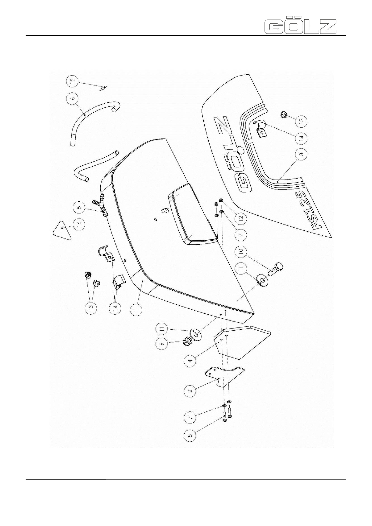
®
FS125
9.4 Schutzhaube - Blade guard - Capot de protection - Beschermkap Zaagblad
- 73-
5009002-00
BA-DE-GB-FR-NL (001)
Page 33

®
FS125
Pos. Art.-Nr.
- - 1 Pos. 1-16 S-Haube kpl. Blade guard
Pos. Art.-Nr.
1 0282 125 6104 1 S-Haube Blade guard
2 - 1
3 - 1 FS125 Aufkleber Sticker Autocollant Zelfklever
4 0282 125 6105 1 Spritzschutz Splash guard
5 0282 130 0527 1 Y-Verteiler Y-Distribution Y-Distributeur Verdeler
6 0282 125 6106 2
7 - 4
8 - 2
9 - 1
10 - 1
11 - 2
12 - 2
13 - 3
14 0282 130 0532 3 15 mm
15 - 1 Aufkleber Sticker Autocollant Zelfklever
Menge
Qty.
Menge
Qty.
Norm Info Bezeichnung Description Désignation Benaming
Capot de
protection
Norm Info Bezeichnung Description Désignation Benaming
Capot de
protection
Ø9×1.5
250 mm
A4,3
ISO 7089
M4x20
ISO 7045
M10
DIN982
M10x35
ISO 4017
A10,5
DIN EN ISO 7093
M4
ISO7040
D4x8
DIN 7337
Aufnahme
Spritzschutz
Schlauch Hose Tuyau Slang
Scheibe Washer Rondelle Ring
Schraube Screw Vis Bout
Mutter Nut Écrou Moer
Schraube Screw Vis Bout
Scheibe Washer Rondelle Ring
Mutter Nut Écrou Moer
Blindniete Blind rivet Rivet aveugle Popnagel
Schlauchschelle
Splash guard
acceptance
Hose clamp Collier Slangbeugel
Levé bavette
anti-projection
Bavette
antiprojection
Beschermkap
Zaagblad vol.
Beschermkap
Zaagblad
Opname
sproeier
Spatrand
16 0295 899 0314 1 Aufkleber Sticker Autocollant Zelfklever
- 74-
5009002-00
BA-DE-GB-FR-NL (001)
Page 34
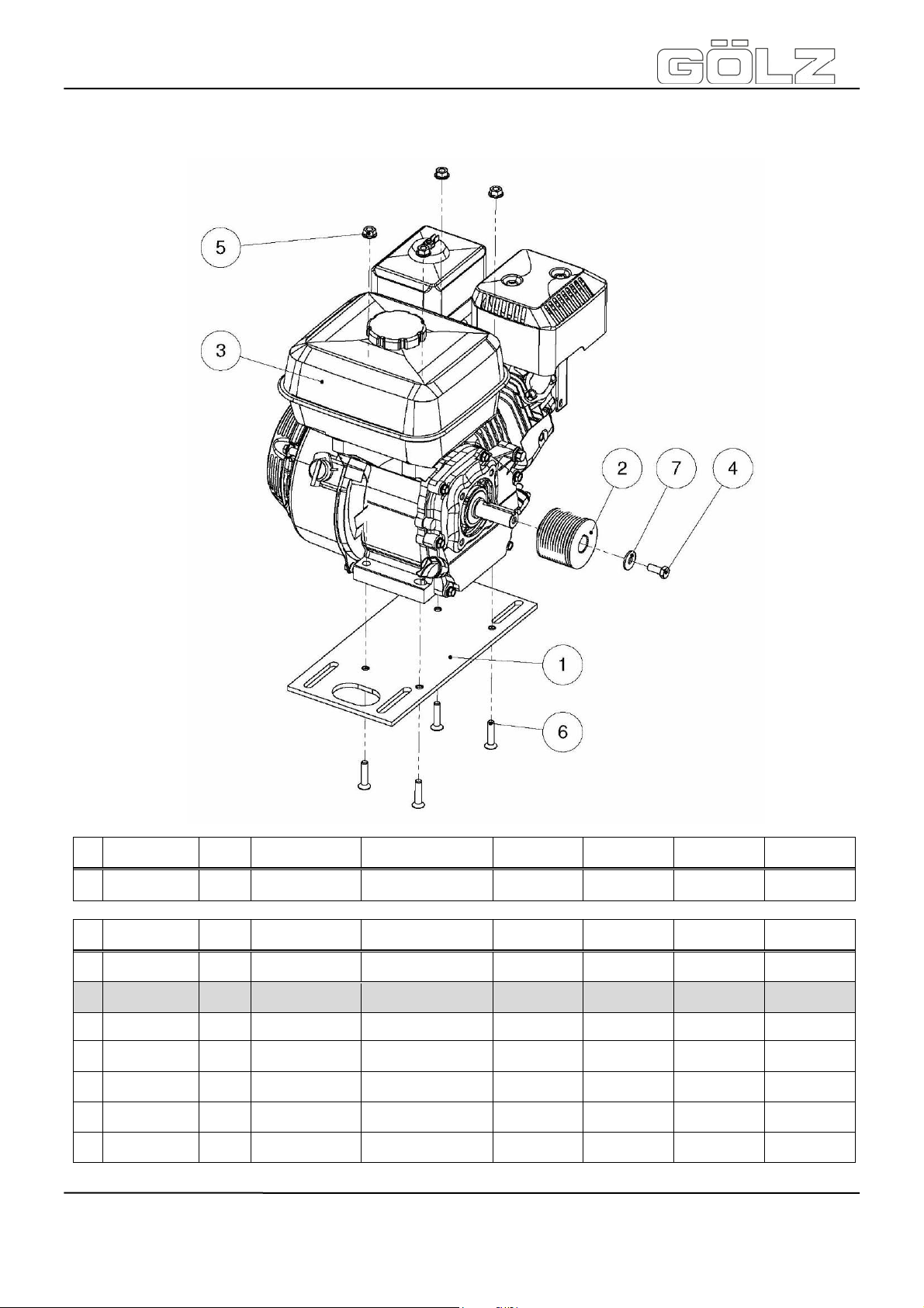
FS125
9.5 Benzinmotor - Engine - Moteur - Motor
Pos. Art.-Nr.
- - 1 Pos. 1-7 Motor kpl.
Pos. Art.-Nr.
1 - 1 Motorplatte Clamping Plate
2 0282 125 6101 1 PK12 62.5
3 - 1 Honda GX 200-S Motor Engine Moteur Motor
4 - 1
5 - 4
6 - 4
7 - 1
Menge
Qty.
Menge
Qty.
Norm Info Bezeichnung Description Désignation Benaming
Engine
complete
Norm Info Bezeichnung Description Désignation Benaming
M8x20
ISO 4017
M8
DIN 6923
M8x35
ISO 10642
A8,4
ISO 7093
Keilrippenscheibe
Schraube Screw Vis Bout
Mutter Nut Écrou Moer
Schraube Screw Vis Bout
Scheibe Washer Rondelle Ring
V-ripped-pulley
Moteur
complète
Platine de
coulissement
V-déchiré
poulie
Motor vol.
Klemplaat
motor
V-riemschijf
- 75-
BA-DE-GB-FR-NL (001)
®
5009002-00
Page 35
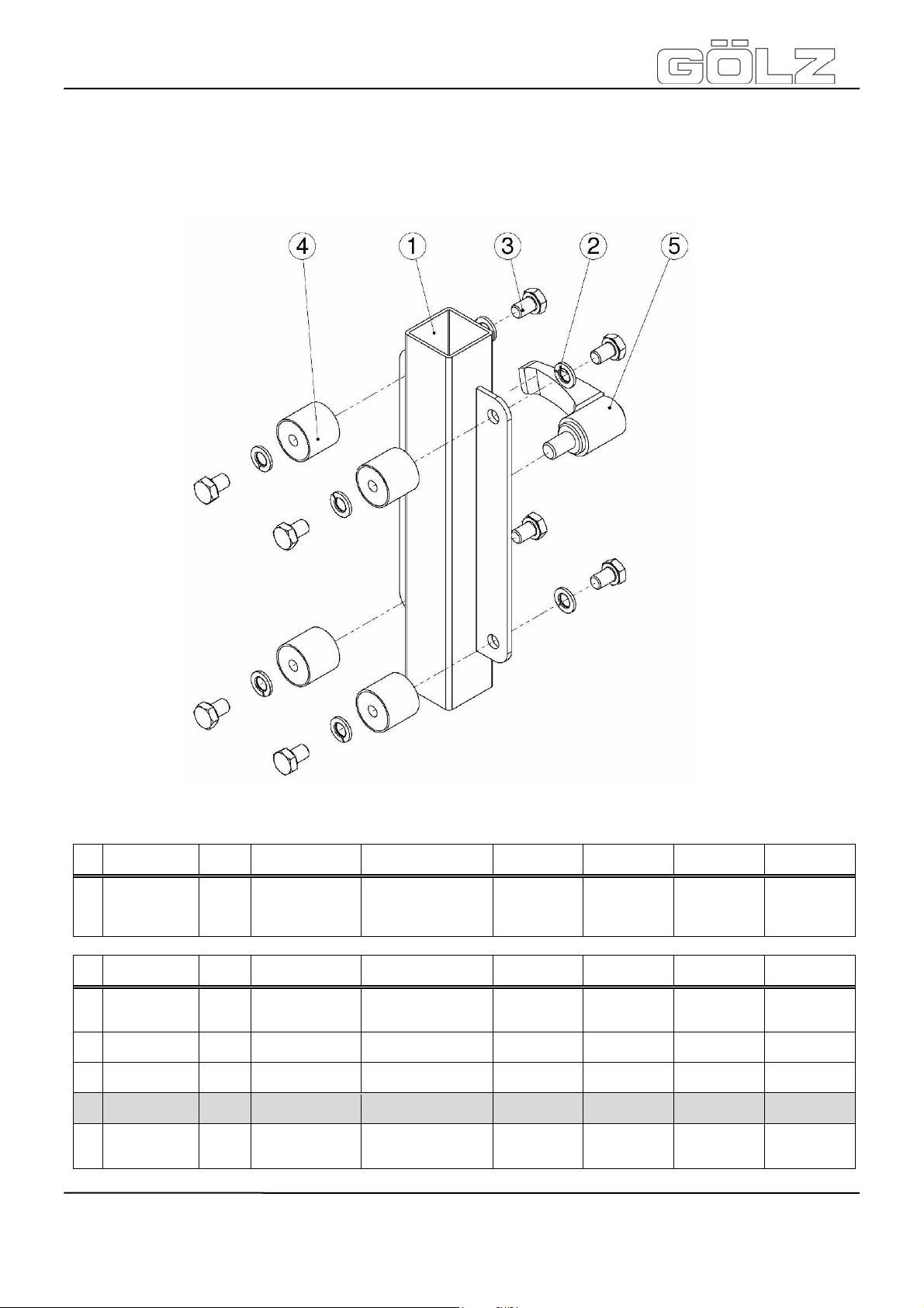
FS125
9.6 Aufnahme Führungsstange - Receiving part guiding rod - Support de
poignée réglable - Opname geleidingsstang
Pos. Art.-Nr.
- - 1 Pos. 1-5
Pos. Art.-Nr.
1 0282 125 6107 1
2 - 8
3 - 8
4 0295 002 0022 4
5 0282 241 0095 -
Menge
Qty.
Menge
Qty.
GN602-78-M10-16-
Norm Info Bezeichnung Description Désignation Benaming
Aufnahme
Führungsstange kpl.
Norm Info Bezeichnung Description Désignation Benaming
Aufnahme
Führungsstange
A8,4
ISO 7089
M8x12
ISO 4017
520511-
25.5-22-M8-50
SW
Gummipuffer Bump rubber Patin
Scheibe Washer Rondelle Ring
Schraube Screw Vis Bout
Klemmhebel Clamping lever
Receiving part
guiding rod
complete
Receiving part
guiding rod
Support de
poignée
réglable
complète
Support de
poignée
réglable
Levier de
serrage
Opname
Geleidingsstang
vol.
Opname
Geleidingsstang
Rubberen
buffer
Klemhefboom
®
- 76-
5009002-00
BA-DE-GB-FR-NL (001)
Page 36

FS125
A
A
A
9.7 Spindelaufnahme - Spindle holder - Support de relevage - As opname
Pos. Art.-Nr.
- - 1 Pos. 1-8
Pos. Art.-Nr.
1 - 1
2 0282 125 6108 1 D12 Augenschraube Eye screw Vis à œil Oogschroef
3 - 1
4 0282 125 6109 1 Tr20x4 Trapezspindel
5 - 2 Distanzstück Spacer Entretoise
6 - 8
7 - 8
8 - 1 M6 DIN71412
Menge
Qty.
Menge
Qty.
Norm Info Bezeichnung Description Désignation Benaming
Spindelaufnahme kpl.
Norm Info Bezeichnung Description Désignation Benaming
Spindelaufnahme
M12
DIN EN ISO 4032
A4
DIN 127
M4x8
ISO 7045
Federring Spring washer
Schraube Screw Vis Bout
utter
Kegelschmiernippel
Spindle holder
complete
Spindle holder
ut
Trapezoidal
spindle
Grease nipple Graisseur
Support de
relevage
complète
Support de
relevage
crou
Trapezspindel Trapezspindel
Rondelle
élastique
s opname
volledig
s opname
oer
fstandring
Veerring
Kogel
smeernippel
®
- 77-
5009002-00
BA-DE-GB-FR-NL (001)
Page 37
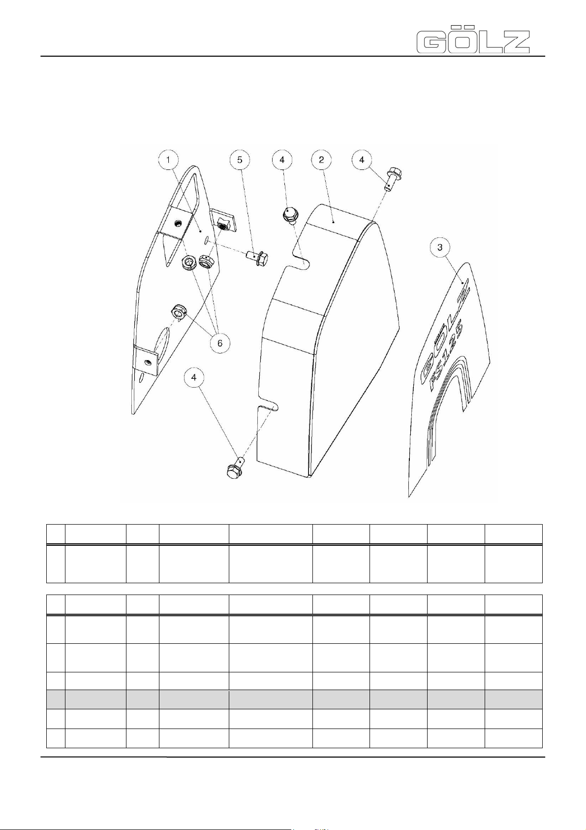
®
FS125
9.8 Keilriemenschutzhaube - V-belt guard - V-belt guard Capot de protection V snaren beschermkap
Pos. Art.-Nr.
- - 1 Pos. 1-6
Pos. Art.-Nr.
1 - 1
2 - 1
3 - 1 Aufkleber Sticker Autocollant Zelfklever
4 - 3
5 - 2
6 - 3
Menge
Qty.
Menge
Qty.
Norm Info Bezeichnung Description Désignation Benaming
Keilriemenschutzhaube
kpl.
Norm Info Bezeichnung Description Désignation Benaming
Keilriemenschutzhaube
Teil 1
Keilriemenschutzhaube
Teil 2
M8×20
DIN EN 1665
M8×16
DIN EN 1665
M8
ISO10511
Schraube Screw Vis Bout
Schraube Screw Vis Bout
Mutter Nut Écrou Moer
V-belt guard
complete
V-belt guard 1
V-belt guard 2
V-belt guard
Capot de
Protection
complète
V-belt guard
Capot de
Protection 1
V-belt guard
Capot de
Protection 2
V snaren
Beschermkap
vol.
V snaren
beschermkap 1
V snaren
beschermkap 2
- 78-
5009002-00
BA-DE-GB-FR-NL (001)
Page 38

FS125
A
9.9 Wassertank - Water Tank - Réservoir d’eau - Watertank
Pos. Art.-Nr.
- 0282 170 6160 1 Pos. 1-4 Wassertank kpl.
Pos. Art.-Nr.
1 0282 170 6162 1 Behälterdeckel Cap
2 0282 170 6161
Menge
Qty.
Menge
Qty.
1 Pos. 2.1 Wassertank Water Tank Réservoir d’eau Watertank
1 GÖLZ Pos. 2.2 Haftetikette Label Autocollant Zelfklever
Norm Info Bezeichnung Description Désignation Benaming
Water Tank
assy.
Norm Info Bezeichnung Description Désignation Benaming
Réservoir d’eau
complet
Couvercle du
réservoir
®
Watertank,
volledig
Deksel reservoir
ansluitstuk
Minikogelkraan
Insteek
aansluiting
Insteek
aansluiting
Opname
watertank
3 0282 170 6164
4 0282 170 6163
1 Pos. 3.1 Anschlussstück Connector Raccord
1 ¼“ Pos. 3.2 Minikugelhahn Mini ball valve
1 Pos. 3.3 Steckanschluss
1 Pos. 3.4 Steckanschluss
1 Pos. 3.5 Schelle Clamp Collier Beugel
1
2
1 Pos. 4.1
2 Ø20 Pos. 4.2 Stopfen Stopple Bouchon Stop
M12
ISO 10511
A13
ISO 7089
Pos. 3.6 Mutter Nut Écrou Moer
Pos. 3.7 Scheibe Washer Rondelle Ring
Aufnahme
Wassertank
Quick
connector
Quick
connector
Support water
reservoir
Robinet à rotule
mini
Accouplement
branchement
d‘eau
Accouplement
branchement
d‘eau
Support de
récipient à eau
- 79-
5009002-00
BA-DE-GB-FR-NL (001)
Page 39
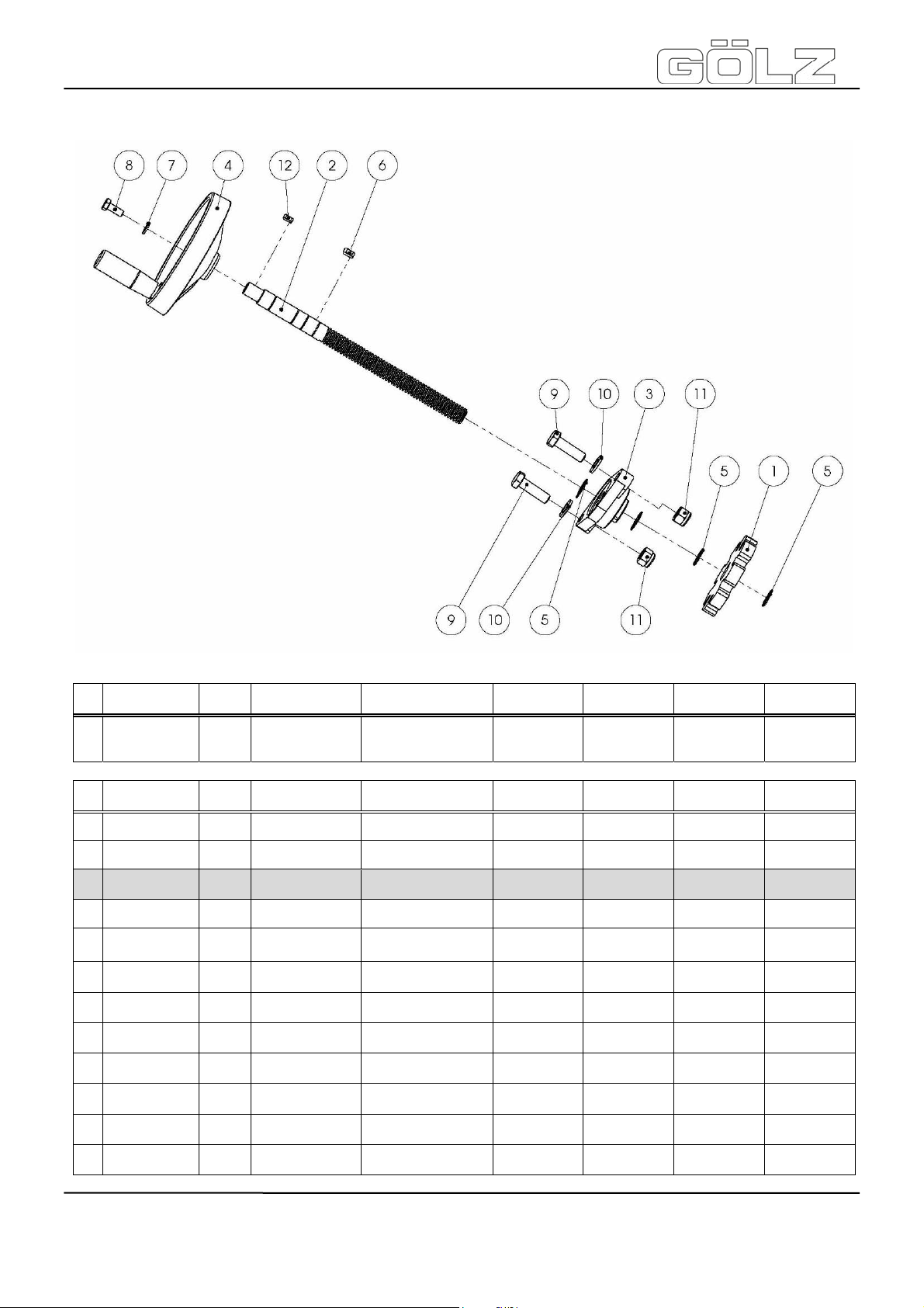
FS125
9.10 Tiefeneinstellung - Pushing bar - Poignée - Schuifbeugel
Pos. Art.-Nr.
- - 1
Pos. Art.-Nr.
1 - 1 Rastscheibe Locking disc Rondelle d’arrêtRastscheibe
Menge
Qty.
Menge
Qty.
Norm Info Bezeichnung Description Désignation Benaming
Tiefeneinstellung kpl.
Norm Info Bezeichnung Description Désignation Benaming
Depth
adjustment
complete
Système de
plongée
complet
Diepte instelling
volledig
®
2 0282 125 6111 1 Spindel Shaft Arbre Spindel
3 0282 240 0022 1 UCFL204-Ø20 Flanschlager Flange bearing
4 0282 125 6112 1 Ø160 Handrad Hand wheel Volant Handwiel
5 - 1
6 - 1
7 - 2
8 - 1
9 - 2
10 - 2
11 - 2
12 - 1
20x1.2
DIN 471
A6x6x14
DIN 6885
A8,4
ISO 7093
M8x20
ISO 4017
M12x40
ISO 4017
A13
ISO 7089
M12
ISO 10511
A5x5x12
DIN 6885
Sicherungsring Circlip Circlip
Passfeder Parallel key Clavette Vlakspie
Scheibe Washer Rondelle Ring
Schraube Screw Vis Bout
Schraube Screw Vis Bout
Scheibe Washer Rondelle Ring
Mutter Nut Écrou Moer
Passfeder Parallel key Clavette Vlakspie
Coussinet avec
flasque
Flenslager
Borgring
- 80-
5009002-00
BA-DE-GB-FR-NL (001)
Page 40
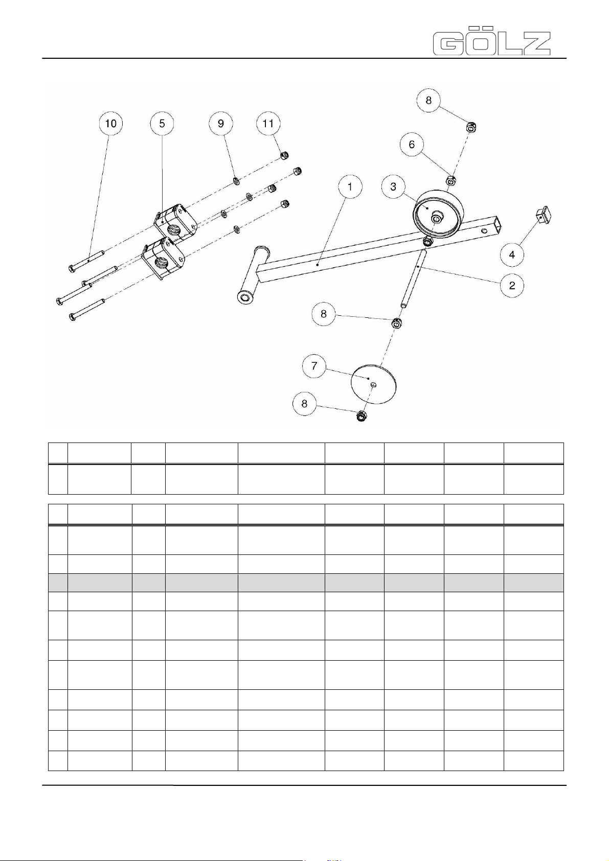
FS125
9.11 Richtungsanzeiger - Pointer unit - Indicateur de direction - Richtingsaanwijzer
Pos. Art.-Nr.
- - 1
Pos. Art.-Nr.
1 0282 170 6113 1
2 - 1 Gewindestange Threaded rod Tige filetée Draadstang
Menge
Qty.
Menge
Qty.
Norm Info Bezeichnung Description Désignation Benaming
Richtungsanzeiger kpl.
Norm Info Bezeichnung Description Désignation Benaming
Aufnahme
Richtungsanzeiger
Pointer unit
complete
Pointer unit
Indicateur de
direction
complète
Indicateur de
direction
Richtingsaanwijzer
volledig
Houder
richtingsaanwijz
er
®
3 0282 120 0084 1 Ø75 x Ø8,2 Rad Wheel Roue Wiel
4 0282 125 6114 1 20 x 20 Stopfen Stopple Bouchon Stop
5 - 2
6 - 1
7 - 1 Schnittanzeiger
8 - 4
9 - 4
10 - 4
11 - 4
HRL-3-A-20-PP-
ST-M-ZN
DIN 3015
M8
ISO 4032
M8
ISO 7040
A6,4
ISO 7089
M6x60
ISO 4017
M6
DIN EN ISO 7040
Mutter Nut Écrou Moer
Mutter Nut Écrou Moer
Scheibe Washer Rondelle Ring
Schraube Screw Vis Bout
Mutter Nut Écrou Moer
Befestigungsschelle
Pipe clamp
Guidance
indicating
needle
Collier de
fixation
Indicateur de
trait de coupe
Bevestigingskle
m
Zaag indicator
- 81-
BA-DE-GB-FR-NL (001)
5009002-00
Page 41
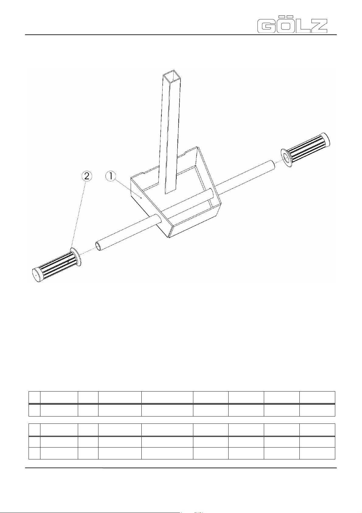
FS125
9.12 Schubbügel - Pushing bar - Poignée - Schuifbeugel
®
Pos. Art.-Nr.
- 0282 125 6115 1 Schubbügel kpl.
Pos. Art.-Nr.
1 - 1 Schubbügel Pushing bar Poignée Schuifbeugel
2 0282 017 9022 2 Griffbezug Soft grip
Menge
Qty.
Menge
Qty.
Norm Info Bezeichnung Description Désignation Benaming
Pushing bar
complet
Norm Info Bezeichnung Description Désignation Benaming
Poignée
complète
Revêtement de
poignée
Schuifbeugelvol
.
Handvaten
- 82-
5009002-00
BA-DE-GB-FR-NL (001)
Page 42

FS125
9.13 Schneidwelle - Blade shaft - Arbre de coupe - Snijdas
- 83-
®
5009002-00
BA-DE-GB-FR-NL (001)
Page 43

FS125
Pos. Art.-Nr.
1 - 1
Pos. Art.-Nr.
1 0282 125 6116 1
2 - 1
3 0282 125 6117 1 Außenflansch Outer flange
4 - 1
5 - 6
6 4
7 - 2 UCFL206-Ø30 Flanschlager Flange bearing
8 - 4
9 0282 125 6100 1
10 - 4
Menge
Qty.
Menge
Qty.
Norm Info Bezeichnung Description Désignation Benaming
Schneidwelle
kpl.
Norm Info Bezeichnung Description Désignation Benaming
Schneidwelle
mit Flansch
A8x7x45
DIN 6885
M20 x 1,5 LH
ISO 8673
A13
ISO 7089
M12
ISO 10511
M12x40
ISO 4017
TB12
PK82.5-L47.5
A13
ISO 7093
Passfeder Parallel key Clavette Vlakspie
Mutter Nut Écrou Moer
Scheibe Washer Rondelle Ring
Mutter Nut Écrou Moer
Schraube Screw Vis Bout
Scheibe Washer Rondelle Ring
Keilrippenscheibe mit
Taper - Buchse
Blade shaft
complete
Blade shaft with
flange
V-ripped-pulley
with Taper Bushing
Arbre de coupe
complète
Arbre de coupe
avec flasque
Flasque
extérieure
Coussinet avec
flasque
V-déchiré
poulie avec
Taper Coussinet
®
Zaagas volledig
Zaagas met
flens
Buitenste flens
Flenslager
V-riemschijf met
Taper - klembus
- 84-
5009002-00
BA-DE-GB-FR-NL (001)
Page 44

FS125
9.14 Transportbügel - Lifting eye - Anneau de lavage - Transportbeugel
Pos. Art.-Nr.
1 - 1
Pos. Art.-Nr.
1 - 1 Transportbügel Lifting eye
2 - 6
3 - 6
4 - 6
Menge
Qty.
Menge
Qty.
Norm Info Bezeichnung Description Désignation Benaming
Transportbügel
kpl.
Norm Info Bezeichnung Description Désignation Benaming
A8,4
ISO 7089
A8
DIN 127
M8x20
ISO 4017
Scheibe Washer Rondelle Ring
Federring Spring washer
Schraube Screw Vis Bout
Lifting eye
complete
Anneau de
lavage
complète
Anneau de
lavage
Rondelle
élastique
®
Transportbeugel volledig
Transportbeugel
Veerring
- 85-
5009002-00
BA-DE-GB-FR-NL (001)
 Loading...