

Page 1

FB 20 P
GB
ZN der Bedienungsanleitung: 5006194-00
Erstellt am: 07/2015
Erstellt von: Sabrina Linden
Datei: K:\KDV\5006xxx\5006194-Bedienungsanleitung\
5006194-00-Bedienungsanleitung-E.doc
GÖLZ® GmbH
Dommersbach 51
D-53940 Hellenthal
Telefon: +49 (0) 2482 12 200 / Telefax: +49 (0) 2482 12 222
E-Mail: info@goelz.de / Internet: www.goelz.de
Original operating instruction and spare parts list
Diamand wet core drill machine
- 1-
5006194-00
BA-E
Page 2

FB 20 P
All rights reserved according to DIN ISO 16016.
No part of this document (instruction manual and spare parts list) may be reproduced, adapted, transmitted,
transcribed, stored on a data medium or be translated into another language without prior written approval of
GÖLZ® GmbH
Dommersbach 51
D-53940 Hellenthal
Guarantee
We reserve the right to amend any information included in this document (manual instruction and spare parts list)
at any time and without prior notice.
GÖLZ® assumes no warranty for these documents.
GÖLZ® shall not be liable for errors in this document (manual instruction and spare parts list) or for any collateral
or consequential damage in connection with shipment, performance or use of the material.
- 2-
5006194-00
BA-E
Page 3
FB 20 P
EG-KONFORMITÄTSERKLÄRUNG EC-DECLARATION OF CONFORMITY
Die Firma Manufacturer La Société
GÖLZ® GmbH
Dommersbach 51, D-53940 Hellenthal
Tel.: +49 (0) 2482 12 200 / Fax: +49 (0) 2482 12 222
erklärt in alleiniger Verantwortung dass
folgende Maschine:
Declare hereby certifies on its sole
responsibility that the following product:
FB 20 P
Diamant-Nass-Kernbohrmaschine
Diamond wet core drill machine
Carotteuse diamant sous arrosage
Seriennummer / Serial number / Numéro de série : ___________________________
auf das sich diese Erklärung bezieht, mit
folgenden Richtlinien übereinstimmt:
2006/42/EG
Sicherheits- und
Gesundheitsanforderung
2004/108/EG
Elektro-Magnetische Verträglichkeit
2006/95/EG
Niederspannungsrichtlinie
2011/65/EU
RoHS
mit folgenden Normen übereinstimmt:
EN 50144-1
EN 50144-2-1
EN 55014-1
EN 6100-3-2
EN 61000-3-3
EN 55014-2
EN 61029-1
Die oben genannte Firma hält
Dokumentation als Nachweis der
Erfüllung der Sicherheitsziele und die
wesentlichen Schutzanforderungen zur
Einsicht bereit.
which is explicitly referred to by this
declaration meet the following directives:
2006/42/EG
Safety and health requirement
2004/108/EG
Electromagnetic compatibility
2006/95/EC
Low voltage directive
2011/65/EU
RoHS
meet the following standards:
EN 50144-1
EN 50144-2-1
EN 55014-1
EN 6100-3-2
EN 61000-3-3
EN 55014-2
EN 61029-1
Documented evidence conforming to the
requirements of the directives is kept
available for inspection at the above
manufacturer’s address.
DECLARATION DE CONFORMITE DE
LA CE
déclare sous sa seule responsabilité
que le produit suivant:
Qui fait l’objet de la présente
déclaration correspond aux directives
suivantes:
2006/42/EG
Prescriptions sanitaire et sécurité
2004/108/EG
Compatibilité électromagnétique
2006/95/CE
Directive basse pression
2011/65/EU
RoHS
aux normes suivantes:
EN 50144-1
EN 50144-2-1
EN 55014-1
EN 6100-3-2
EN 61000-3-3
EN 55014-2
EN 61029-1
Pour faire foi de la conformité et du
respect des règles de sécurité, la documentation peut être consultée au siège
de la Société susmentionnée.
…………………………………………………………………………………
Hellenthal, den 03.07.2015
Geschäftsführer / General Manager /
Président-directeur général
B. Schmitz
- 3-
5006194-00
BA-E
Page 4

FB 20 P
Contents
1. Symbol- and Pictograph description .......................................................................... 5
1.1 Function description ................................................................................................ 5
2. General instructions .................................................................................................... 5
2.1 Application .............................................................................................................. 5
2.2 Safety ...................................................................................................................... 6
3. Transport and storage ................................................................................................. 6
3.1 Transport ................................................................................................................. 6
3.2 Storage ................................................................................................................... 6
4. Main dimensions and technical data .......................................................................... 7
4.1 Dimensions ............................................................................................................. 7
4.2 Technical data ......................................................................................................... 7
5. Commissioning ............................................................................................................ 8
5.1 Changing gear ........................................................................................................ 8
5.2 Safety coupling ....................................................................................................... 8
5.3 Core bits .................................................................................................................. 9
5.4 To change a core bit ............................................................................................... 9
6. Safety instructions ....................................................................................................... 9
7. Servicing and care ..................................................................................................... 10
7.1 Daily care .............................................................................................................. 10
7.2 After approx. 150 hours of use .............................................................................. 10
7.3 After approx. 250 hours of use .............................................................................. 10
7.4 Quarterly ............................................................................................................... 10
8. Speed adjustment dependent on the cutting speed ............................................... 11
9. Warranty ...................................................................................................................... 12
10. General safety instructions ....................................................................................... 12
11. Spare parts list ........................................................................................................... 14
11.1 Using the spare parts list ....................................................................................... 14
11.1.1 Safety regulation...................................................................................................... 14
11.1.2 Ordering information ................................................................................................ 14
11.1.3 Distribution agencies ............................................................................................... 15
11.2 Wearing parts ........................................................................................................ 16
12. Exploded view and spare parts list .......................................................................... 17
- 4-
5006194-00
BA-E
Page 5
FB 20 P
Special designs and versions may differ from the standard models in terms of their technical details. If any points
are unclear, we urgently recommend that you contact GÖLZ® GmbH, indicating the machine type and machine
number.
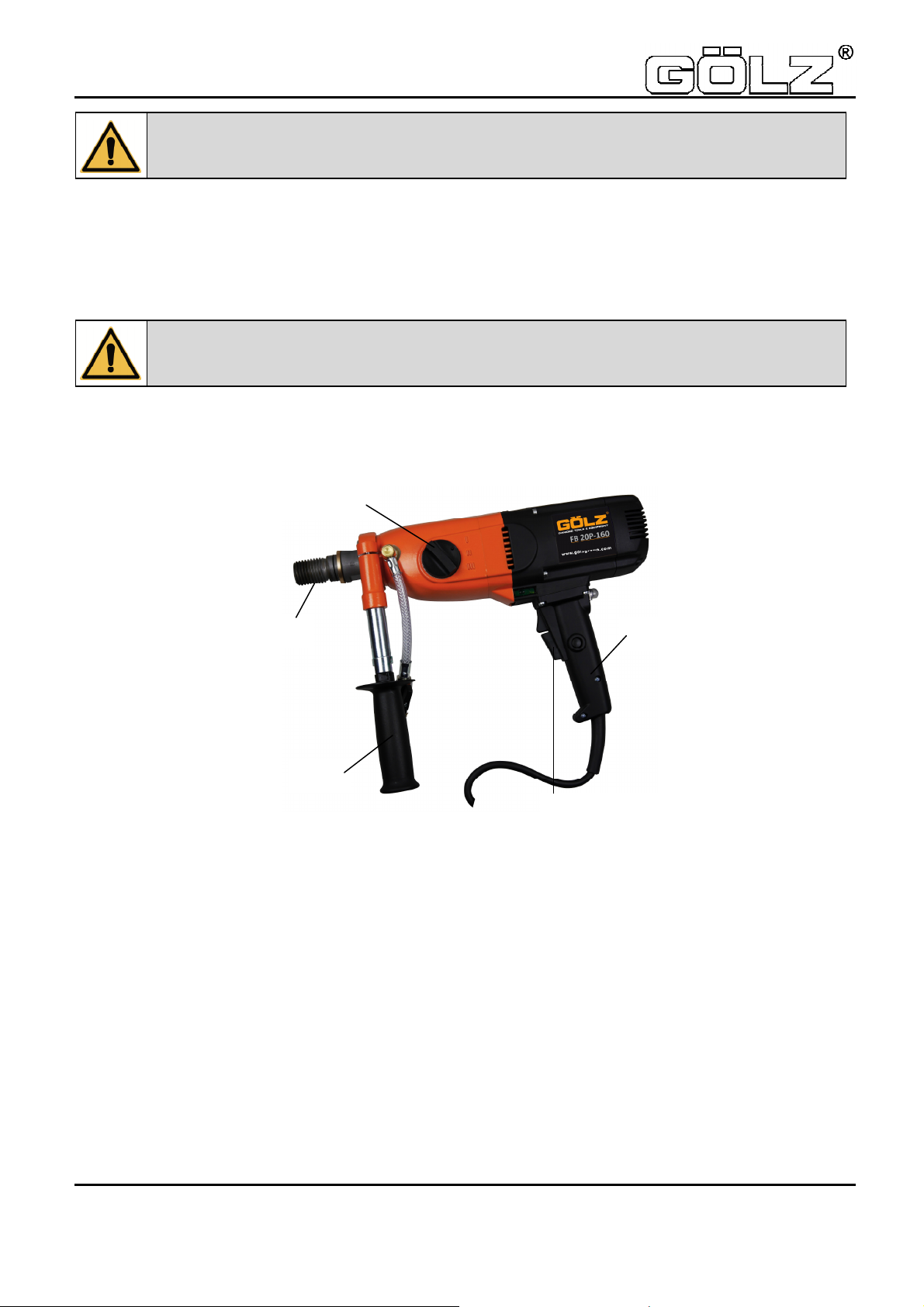
1. Symbol- and Pictograph description
1.1 Function description
2. General instructions
2.1 Application
The machine may be used in accordance with the data shown on the model plate. The details in the quotation
and order confirmation also apply for the use of special machines.
The machines generally comply with safety class II, this alone ensures the complete protection of the RCCB or
PRCD.
When using suitable core bits it is possible to drill holes in the most diverse materials:
• Concrete (even with thick reinforcement steel)
• Sandstone and limestone
• All building materials for solid walls
• Asphalt floors
It is compulsory to observe the safety instructions included in this manual!
This sign tells you rules, if you not pay attention for this your health and the function of the
machine is in danger. You have no warranty if the machine breaks down because you not
looking about this.
Gear control
Drill-spindle
Handle
Switch on/off
Handle
- 5-
5006194-00
BA-E
Page 6

FB 20 P
persons who have suitable training and qualifications.
For stand-mounted drilling the machine may have the following
• a personnel safety switch (RCCB or PRCD) on the machine itself or
• a coded (1 h) plug, which is connected to the 115 V mains via a safety box (IP44) with an RCCB.
The FB 20 P has in both types, voltage 110 V and 230 V, an integrated PRCD-safety switch in the cable.
The core drilling machines comply with the regulations of the “Stone and Earth” professional association dated
July 1989. They are machines of category II, which means that they must be mounted on stands and stable
(pursuant to DIN 57100 and VDE 0100), and the stand must be fitted with the following
• reversing lock
• water extraction device.
2.2 Safety
The following points are to be given special attention:
• the technical data and details of the permitted use of the machine (commissioning, ambient and
• the relevant accident prevention regulations
• the correct use of tools
• the use of personal safety equipment
3. Transport and storage
3.1 Transport
3.2 Storage
If possible, the storage site should be dry, clean and have a constant temperature. To ensure that the film of
lubricant in the bearings and sealing system is not lost, the motor shaft should be turned through several
revolutions by hand after a lengthy period of storage, for example at monthly intervals. The roller bearings in the
motors should be replaced (or regreased) if the period between delivery and commissioning is over four years. If
the machines are stored in adverse conditions, this period may differ considerably.
The machine is a pure wet drill machine.
Dry drilling can cause damage to the shaft sealing rings.
Before using the machine for the first time, check that the conformity of the data on the
model plate with the mains voltage and frequency. Voltage deviations of ± 5 % and/or
voltage deviations of ± 2 % are permissible. Repairs must only be completed by quality
operating conditions) which are set out in the catalogue, the operating manual, the model plate data and
other product information,
The machine is to be checked for signs for transport damage on receipt. Any damage must
be documented in writing.
- 6-
5006194-00
BA-E
Page 7
FB 20 P
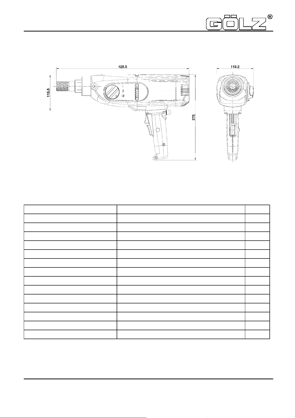
4. Main dimensions and technical data
4.1 Dimensions
(Representation without additional handle)
4.2 Technical data
Rated voltage 230 V
Current consumption 10 A
Power requirement 2200 W
Frequency 50 - 60 Hz
Idling speed 950 / 2150 / 4450 min-1
Full speed 500 / 1200 / 2500 min-1
Output rating 1300 W
Torque 25 / 10,5 / 5 Nm
Drilling diameter 150 / 50 / 15 mm
Weight 7,4 kg
Core bit connection UNC 1 ¼ / R ½ “
Overload coupling torque 12 Nm
Noise pressure level (EN 50144) 89 dB (A)
Sound power level (EN 50144) 102 dB (A)
Vibration (EN 50144) < 2,5 m/s²
- 7-
5006194-00
BA-E
Page 8
FB 20 P
5. Commissioning
Check that the mains voltage is identical to the voltage specified on the model plate.
Stand-mounted:
Secure the machine and the water collection device on the drill stand with a reverse lock. The drill stand should
have high rigidity and precise, low-play guides. Ensure that the machine axis is parallel to the drill stand axis.
Insert the core bit and set the speed. Setting instructions are given in chapter 8.
Connect the water supply. Important: Do not exceed the max. water pressure of 3 bar.
Both voltage versions of FB 20 P (110V and 230V) are equipped with a PRCD-safety switch in the cable, so the
FB 20 P can be directly connected to the main supply.
Manually controlled:
When drilling a hole ensure that you are on a secure surface. Make particularly sure the core bit is not bent
during the drilling process and hold the core drilling machine as rigid as possible. Concentrate hard on the work
since if the core bit suddenly blocks, despite the low setting of the safety slip clutch, high forces may be
generated. If you let go of the core drilling during the drilling process, you may suffer serious injury.
Only used three-core extension cables with a protective conductor and an adequate cross-section. If the crosssection is too low you may suffer excessive power loss and the motor and cable may overheat. An extension
cable must be secured with an overload switch. Recommended cable cross-sections:
Recommended cable cross-sections:
Rated current = 9 A
Cable length m 7,5 15 25 30 45 60
Cable cross-section mm2 2,5 2,5 2,5 2,5 2,5 4
When drilling a hole ensure that you have sufficient cooling water. Only use clean tap water, do not use dirty or
waste water. Adjust the supply to the core bit diameter and drive rating of the core drill so that you do not exceed
the rated current.
5.1 Changing gear
Move the gear switch handle by approx. 40° to the next higher or lower gear. If necessary (if it is difficult to
engage the gear) turn the drive spindle briefly by hand until the gear engages easily. Never use tools (pliers,
hammer, etc.) to change gear since otherwise gear damage will be inevitable.
Never change gear using force and only do so when the machine is slowing down or at a
standstill.
5.2 Safety coupling
The values set out in the table are theoretical values and may be used to provide a rough guide for gear
changing. Since a whole range of other parameters also plays a major role in adjusting the speed, we cannot
offer any guarantee if the tool is damaged when using the values in the table. Drilling work for which the speeds
are outside the range of the core drill (values printed in italics), should only be completed with extreme care and
by trained personnel.
- 8-
5006194-00
BA-E
Page 9

FB 20 P
5.3 Core bits
All core bits with a connection thread of UNC 1 ¼ “ or R ½ “ can be used.
Adapters can be supplied to allow core bits with other connection systems to be used. Only use core bits that are
suitable for the type of stone.
You will keep the machine in good condition if you only use core bits that are concentric and not deformed ones.
Ensure that the diamond segments have an adequate undercut against the core bit body.
5.4 To change a core bit
The drill spindle has a right-handed thread.
Always use a 32 mm open-ended spanner to hold against the drill spindle. Never release the core bit with
(hammer) blows since this will damage the machine.
The core bit can be removed more easily if you apply a little waterproof grease to the drill spindle thread.
6. Safety instructions
• if you intend to leave the machine unsupervised,
• for attachment and disconnection work,
• if the voltage drops (below 200 V),
• for adjustments or for fitting an accessory,
Switch off the machine if it stops for any reason. This will prevent its starting suddenly when it is not under
supervision.
Do not use the machine if
• part of the casing is missing or defective,
• If water drips out of the overflow hole, stop work and have the machine inspected by an authorized
• Only drill above your head with suitable safety equipment (water collector), RCD and transformer
• After a fault do not switch on the machine again until the core bit can be turned easily.
• Check the area you wish to drill with a line detector to prevent drilling through electric cables, water
• or gas lines, etc.
• the switch, lead or plug connector has suffered damage (conduct a visual inspection every day).
• Cooling water must not be allowed to ingress into the motor or the electrical components when operating
• the core drill in any position.
Do not expose the tool to rain and use not in humidity or wet environment. Use a good lightning. Do not use
the tool near flammable fluids or gas air mixes.
To use wrong tools or accessories is danger for your life.
Only use the machine under supervision. Disconnect the mains plug and check that the
switch has been turned off,.
service contractor.
protection class II.
- 9-
5006194-00
BA-E
Page 10

FB 20 P
7. Servicing and care
7.1 Daily care
Ensure that no water escapes from the overflow hole. This will cause gear damage and may reduce the electrical
safety of the machine. In this case please contact an authorised service centre.
Inspection the machine for signs of damage to the switch, mains lead or plug connector.
After completing the drilling work clean the machine. Grease the core bit mounting thread. The ventilation slits
must be kept clean and open at all times. Ensure that no water gets into the machine whilst you are cleaning it.
To ensure that the sealing function is maintained, oil the drill spindle:
• Disconnect the machine from the water supply. Open the water connection shut-off cock and insert a
7.2 After approx. 150 hours of use
After the first 150 hours of use, the gearbox oil must be changed.
7.3 After approx. 250 hours of use
Have the carbon brushes checked, and replaced if necessary, by an electrician.
Remove the screws. Pull the cap off the motor casing. Remove the carbon brushes screws, raise the carbon
brushes retaining springs and take out the carbon brushes. Clean the carbon brush holder and collector with a
paintbrush.
Fit new carbon brushes following the above instructions in reverse. Position the cap and secure it with the
screws. Fit the cap on the motor casing by tapping it gently with a rubber mallet or the like. Tighten the screws.
Release the stress by tapping the cap twice. Avoid adjusting the carbon retaining springs. Only use original spare
parts.
7.4 Quarterly
Have the cable, switch and plugs inspected by an expert (pursuant to VBG4) and document the process.
Replacing the gearbox oil will considerably extend the service life of the gear.
Before starting any servicing or repair work always disconnect the mains plug.
After all repairs you must have the core drilling machine inspected by an electrician
(statutory regulation pursuant to VBG4 since 1.1.1990).
drop of oil, close the shut-off cock, place a few drops of oil into the overflow hole and turn the machine
briefly by hand.
- 10-
5006194-00
BA-E
Page 11

FB 20 P
3 4 5 6 7 [m/s]
Bit
capacity
Ø concrete
concrete
rock
[mm]
reinforced
8. Speed adjustment dependent on the cutting speed
The values set out in the table are theoretical values and may be used to provide a rough guide for gear
changing. Since a whole range of other parameters also plays a major role in adjusting the speed, we cannot
offer any guarantee if the tool is damaged when using the values in the table. Drilling work for which the speeds
are outside the range of the machine (values printed in italics), should only be completed with extreme care and
by trained personnel.
15 3820
20 2900 3820
25 2500 3056 3820
30 1910 2500 3183 3820
35 1637 2183 2728 3274 3820 3rd gear
40 1432 1910 2500 2865 3342 3rd gear
45 1273 1698 2122 2500 2971 3rd gear
50 1200 1528 1910 2292 2674 3rd gear
55 1042 1400 1736 2083 2500 3rd gear
60 955 1273 1592 1910 2228 2 or 3
65 881 1200 1400 1763 2057 2 or 3
70 819 1091 1364 1637 1910 2 or 3
75 764 1019 1273 1528 1783 2 or 3
80 716 955 1200 1400 1671 2 or 3
85 674 899 1123 1348 1573 2 or 3
90 637 849 1061 1273 1485 2 or 3
95 603 804 1005 1200 1400 2 or 3
100 573 764 955 1146 1337 2 or 3
110 521 694 868 1042 1200 2nd gear
120 500 637 796 955 1114 1 or 2
130
140
150
160
170
180
190
200
210
220
230
240
250
260
441
409
382
358 477
337 449
318 424
302 402
286 382 477
273 364 455
260 347 434
249 332 415
239 318 398 477
229 306 382 458
220 294 367 441
5093 6366 7639 8913
4775 5730 6685
4584 5348
4456
588 735 881 1028 1 or 2
546 682 819 955 1 or 2
500 637 764 891 1 or 2
597 716 836 1 or 2
562 674 786 1 or 2
531 637 743 1st gear
500 603 704 1st gear
573 668 1st gear
546 637 1st gear
521 608 1st gear
500 581 1st gear
557 1st gear
535 1st gear
500 1st gear
3rd gear
3rd gear
3rd gear
3rd gear
- 11-
5006194-00
BA-E
Page 12

FB 20 P
9. Warranty
In keeping with our terms of sale, we offer a warranty for six months from the date of sale. This refers to the free
repair of material and workmanship defects, which were verifiably caused before the sale.
An original purchase document must always be submitted in case of a warranty claim. It has to contain the full
address of the dealer, the date of purchase and the type designation of the product. The operating instructions of
the particular product and the safety instructions must have been followed.
Damages resulting from operational faults cannot be acknowledged as warranty cases.
The products of the manufacturer have been developed and produced for specific applications. No warranty
claim is accepted in case of non-compliance with the due employment according to the operating instructions, in
case of the employment for other purposes than originally intended or the employment of inadequate
accessories.
The periodical maintenance and cleaning of the products according to the directions of the operating instructions
is absolutely necessary. The intervention of third persons (opening the machine) renders any warranty claim void.
Maintenance and cleaning operations cannot be claimed on the basis of warranty.
Make sure only original spare parts and original accessories are used. They are available at the authorized
specialized product dealer. If non-original parts are used, consequential damages and increased hazard cannot
be ruled out. The producer is not liable for such damages. Disassembled or partially disassembled hand saws
and those repaired with non-original parts are excluded from the warranty.
Certain components, such as carbon brushes, ball bearings, switches, power-supply lines, gaskets, etc., are
exposed to usage dependent or to normal wear. These wearing parts are not object of this warranty.
Wearing parts are marked on the spare parts lists.
10. General safety instructions
Read and follow these instructions before you use the tool. Keep these safety instructions in a safe place.
Keep your workplace tidy. Untidiness in the workplace can cause accidents.
Protect yourself from electric shocks. Refer to the applicable regulations. Avoid physical contact with earthed
parts, such as pipes, heaters, furnaces and refrigerators.
Keep children away. Do not allow other people to touch the tool or cable, keep them away from where you are
working.
Keep your tools in a safe place. Unused tools should be kept in a dry, locked room out of the reach of children.
Do not overload your tool. It will work better and more safely in the specified capacity range.
Use the correct tool. Do not use tools that are too weak or mounted tools for heavy work. Do not use tools for
purposes and work for which they have not been designed.
Wear suitable clothing. Do not wear excessively baggy clothing or jewellery, which may be caught by moving
parts. For working outdoors, we recommend the use of rubber gloves and sturdy shoes. Wear a hairnet if you
have long hair.
Use goggles. Use a breathing mask for work that generates dust.
Do not use the cable for any purpose other that that for which it is designed. Do not carry the tool by the cable
and do not use it to pull the plug out of the socket. Protect the cable from heat, oil and sharp edges.
Check the connection lead and plug every time before you use the tool for signs of damage. If they are damaged,
have them replaced by a specialist. Always keep the connection lead away from the working area of the machine.
Secure the workpiece. Use clamps or a vice to hold the workpiece. This will make it more secure that if you hold
it in your hand and will allow you to use both hands to control the machine.
Do not overstretch yourself. Avoid abnormal body positions. Ensure that you have a stable area on which to
stand and keep your balance at all times.
Look after your materials with care. Keep your tools sharp and clean so that they produce good safe results.
Check the plug and cable at regular intervals and have them replaced by a specialist if they suffer any damage.
Check the extension cable at regular intervals and replace damaged cables.
Keep the handles free of oil and grease.
Disconnect the mains plug from the supply when the tool is not in use and when changing the tool.
Do not leave a tool spanner on the tool. Before switching on the tool check that the wrench and setting tools have
been removed.
Avoid the machine starting when you do not intend it to. Do not carry a tool that is connected to the mains supply
with your finger on the switch. Ensure that the switch is turned off when you connect the tool to the mains supply.
- 12-
5006194-00
BA-E
Page 13

FB 20 P
Electric tools outdoors and in wet areas: Mobile tools which are used outdoors should be connected to the mains
supply using a residual-current circuit breaker or the like for added safety. This is particularly important when
working with freehand tools. If there is a water supply, you should use an isolation transformer and a voltage
supply of 115 V; please specify in your order.
For outdoors work, only use extension cables, which are approved for this purpose and marked accordingly.
Be vigilant at all times. Watch your work. Proceed sensibly. Do not use the tool if you are not concentrating fully
on what you are doing.
Important:
Safety equipment (such as overcurrent protection devices, undervoltage trips, safety couplings etc.) are tools but
do not offer guaranteed safety. As a responsible manufacturer we tailor these tools to each other so that they
offer the best possible protection. But without the care and caution of the use, these tools may even cause
damage it they are not used properly. Have the slip couplings, in particular, checked during the quarterly
inspection to ensure that it is correctly adjusted and functions properly. This inspection should be conducted by
the manufacturer or an authorised service outlet and documented.
Check the machine every day for signs of damage, conduct a visual inspection:
Before reusing the tool, carefully check the safety equipment or slightly damaged parts to ensure that they offer
perfect and proper function. Check that all moving parts function correctly, that they do not jam and that none of
the parts are damaged. All parts must be correctly fitted and satisfy all the conditions to ensure the perfect
operation of the tool. Damaged safety equipment and parts must be repaired or replaced properly by a specialist
service contractor. Do not use any tools, which cannot be switched on and off using the switch. Pay particular
attention to ensuring electrical safety: Cables? Plugs? Switches? Do all the components satisfy safety
regulations?
Repairs may only be completed by trained personnel. Before being used for the first time and after all repair
work, the safety of electric tools must be checked by an electrician pursuant to VBG 4, § 5. This inspection must
also be conducted and documented at regular intervals – at least once per year.
Please note that as the operator you are responsible for complying with any additional regulations. For example if
electric tools are used in a wet and/or damp environment, the regulations of the ”Stone and Earth” Professional
Association must be satisfied.
- 13-
5006194-00
BA-E
Page 14

FB 20 P
11. Spare parts list
11.1 Using the spare parts list
The spare parts list is not a mounting or dismounting instruction. The only purpose of the spare parts list is to
easily and quickly find spare parts which can be ordered with distribution agencies, see chapter 11.1.3
"Distribution agencies".
11.1.1 Safety regulation
Using this spare parts list for mounting or dismounting purposes is not permitted. For assembly and disassembly
work exclusively the corresponding descriptions in this operating manual are to be followed.
Danger: Mounting or dismounting assembly groups can give rise to risks which are not
mentioned in the spare parts list!
Danger: Non-observance of this instruction can result in injury which, in the worst case,
can result in death!
11.1.2 Ordering information
Note: In order to avoid wrong deliveries the information the ordering information should be
checked for accuracy and completeness before sending it! Completely indicate the delivery
address!
500 1200 2500
- 14-
5006194-00
BA-E
Page 15

FB 20 P
So bekommen Sie schnell und
richtig Ihr Ersatzteil
• Maschinentyp gemäß
• machine type according to
Typenschild
• Baujahr gemäß Typenschild
• year of manufacture according
• Artikelnummer gemäß
• order number according to
Ersatzteilliste
• Maschinennummer gemäß
• serial number according to
Typenschild
Für Bestellungen, Fragen und In-
formationen wenden Sie sich bitte
an die zuständigen Stellen
11.1.3 Distribution agencies
Deutschland – Germany - Allemagne
GÖLZ® GmbH
Dommersbach 51
DE-53940 Hellenthal
Tel: +49 (0)2482-12 200
Fax: +49 (0)2482-12 222
E-Mail: info@goelz.de / Internet: www.goelz.de
Always indicate
nameplate
to nameplate
spare part list
nameplate
For orders, questions and
information, please contact the
competent departments.
Pour obtenir rapidement les
pièces de rechange indiquer
• type de la machine conforme
de plaque d'identification
• Année de construction selon
plaque d'identification
• Numéro de l'article selon la liste
des pièces de rechange
• numéro de la machine conforme de plaque d'identification
Pour les commandes, questions et
informations, veuillez-vous
adresser aux points de ventes
correspondants.
Österreich - Austria - Autriche
GÖLZ® Ges.m.b.H
Samstraße 52
A-5020 Salzburg
Tel: +43 (0) 662 - 43 81 75
Fax: +43 (0) 662 - 43 07 34
E-Mail: info@goelz.at / Internet: www.goelz.at
Großbritannien - Great Britain - Grande-Bretagne
GÖLZ® (UK) Ltd.
Unit A5, Springhead, Enterprise Park
Northfleet
Kent DA11 8HB
Tel: +44 1 474321679
Fax: +44 1 474321477
E-Mail: info@goelz.co.uk / Internet: www.goelz.co.uk
Australien - Australia - Australie
GOLZ® Pty Ltd.
44 Stanley Street
Peakhurst, NSW 2210
Tel: +61 (0) 2 9534 5599
Fax: +61 (0) 2 9534 5588
E-mail: info@golz.com.au / Internet: www.golz.com.au
Frankreich - France - France
GÖLZ® S.A.S.
1, rue de la Mairie
F-67370 Berstett
Tel: +33 (0)3.88.59.43.00
Fax: +33 (0)3.88.59.47.77
E-Mail: info@golz.fr / Internet: www.golz.fr
Benelux
GÖLZ® Benelux
Eupener Straße 61
BE-4731 Raeren-Eynatten
Tel: +49 (0)2482-12 200
Fax: +49 (0)2482-12 222
E-Mail: benelux@goelz.de / Internet: www.goelz-online.com
USA
GOLZ® L.L.C.
5860 East Osage Ridge Lane
Columbia MO 65203-6018
Tel: +1 573 474 4961
E-Mail: info@golzusa.com / Internet: www.goelz-online.com
- 15-
5006194-00
BA-E
Page 16

FB 20 P
11.2 Wearing parts
Wearing parts for construction devices mentioned in the operating manual such as drilling and sawing
machines.
Wearing parts are the parts subject to operation-related (natural) wear during proper use of the device. The
wearing time cannot be uniformly defined, and differs according to the intensity of use. The wearing parts must
be adjusted, maintained and, if necessary, replaced for the specific device in accordance with the manufacturer’s
operating manual. Operation-related wear is not a reason for defect claims.
Wearing parts of this machine are grey marked in the spare parts list.
• Feed and drive elements such as toothed racks, gearwheels, pinions, spindles, spindle nuts, spindle
bearings, cables, chains, sprockets, belts
• Seals, cables, hoses, packings, connectors, couplings and switches for pneumatic, hydraulic, water,
electrical and fuel systems
• Guide elements such as guide strips, guide bushes, guide rails, rollers, bearings, sliding
protection supports
• Clamping elements for quick-separating systems
• Flushing head seals
• Slide and roller bearings that do not run in an oil bath
• Shaft oil seals and sealing elements
• Friction and safety clutches, braking devices
• Carbon brushes, commutators / armatures
• Easy-release rings
• Control potentiometers and manual switching elements
• Securing elements such as plugs, anchors, screws and bolts
• Fuses and lamps
• Auxiliary and operating materials
• Bowden cables
• Discs
• Diaphragms
• Spark plugs, glow plugs
• Parts of the reversing starter such as the starting rope, starting pawl, starting roller and
starting spring
• Sealing brushes, rubber seals, splash protection cloths
• Filters of all kinds
• Drive rollers, deflection rollers and bandages
• Cable anti-twist elements
• Running and drive wheels
• Water pumps
• Cut-material transport rollers
• Drilling, parting and cutting tools
• Energy storage
- 16-
5006194-00
BA-E
Page 17

FB 20 P
12. Exploded view and spare parts list
- 17-
5006194-00
BA-E
Page 18

FB 20 P
l
actuating wheel
Pos. K.-Art.-Nr. Art.-Nr.
Menge
Qty.
Norm Info Bezeichnung Description Désignation
- 03P31000
1
- 03P32000 110V
2 - 73P31400 1 - -
3 - 80410061 1 6005 2RS - Rillenkugellager
4 - 80201531 1 JV47 - Sicherungsring Locking ring Circlip
5 - 7B301213 1 - -
6 -
7 -
8 - 80200806 1 - - Druckfeder
9 - 80410081 2 Ø5 - Kugel Ball Balle
10 - 80201492 1 AV 25 - Sicherungsring Locking ring Circlip
11 - 83000219 2 25x42x7 - Wellendichtring Shaft seal ring
12 - 80201493 1 JV 40 - Sicherungsring Locking ring Circlip
13 - 83000226 1 25x40x7 - Wellendichtring Shaft seal ring
14 - 7B401104 1 Losrad, kpl.
15 - 7B300774 1 Schaltrad 1
16 - 7B401105 1 Lagerhülse Bearing sleeve Douille
-
-
1 1
- - - -
- - - -
230V
FB20 P FB20 P FB20 P
Getriebegehäuse
Bohrspindel,
kpl.
gearbox
housing
Grooved ball
bearing
Drill spindle
Compression
spring
Loose wheel
complete
Switchactuating whee
Carter de boîte
de vitesses
Roulement
rainuré à billes
Axe de perçage
complète
Ressort à
pression
Bague
d’étanchéité
Bague
d’étanchéité
Roue de
commande
complète
Roue de
commande 1
17 - 80201641 1 15x21x1 Paßscheibe Fitting washer Clavette
18 - 80201322 1 15x1 Sicherungsring Locking ring Circlip
19 - 80201637 1 A4x4x45 Paßfeder Fitting key Clavette
20 - 73P31480 1 Schaltrad
21 -
22 -
23 -
24 - 80200524 1
25 - 80700506 1 Schaltgriff Switch button
26 - 83000224 1 24x2 O-Ring O-ring Joint torique
27 - 7B401781 1 Hülse Bush Douille
28 - 7B401842 1 Schalthebel, kpl.
29 -
30 -
-
-
-
-
-
- - - -
- - - -
- - - -
Ausgleichsscheibe
- - - - - -
- - - - - -
Switch-
Disc
Gear lever
complete
Roue de
commande
Levier de
contrôle
Levier de
contrôle
complète
- 18-
5006194-00
BA-E
Page 19

FB 20 P
- 19-
5006194-00
BA-E
Page 20

FB 20 P
Pos. K.-Art.-Nr. Art.-Nr.
31 - 80201536 1 40x16 PT-Schraube PT-screw Vis PT
32 - 80420131 1 HK1210 Nadelhülse
33 - 80410099 1 6200 Rillenkugellager
34 - 73T11493 1 Kupplung, kpl.
35 - 73T11500 1 Vorlegewelle Countershaft
36 - 83000042 1 KEIV 15x21x3 Wellendichtring
37 - 85000259 2 Bremsscheibe Braking disk
38 - 73T22440 1 Vorlegerad
39 - 7B401041 1 Lagerhülse
40 - 73T2244U 1 Vorlegerad, kpl.
41 - 85000260 1 Druckscheibe
42 - 80200716 2 28x14x1,5 Tellerfeder
43 - 80201007 1 M10x1 Mutter
44 - 80420105 1 HK0808 Nadelhülse
45 - 80200582 1 4x12 Steckkerbstift
46 - 73P31610 1
47 - 83000173 1 90x2 O-Ring O-ring Joint torique
Menge
Qty.
Norm Info Bezeichnung Description Désignation
Getriebelagerschild
Needle
sleeve
Grooved ball
bearing
Clutch
complete
Shaft seal
ring
Reduction
wheel
Bearing
sleeve
Reduction
wheel
complete
Pressure
washer
Spring
washer
Hexagonal
nut
Needle
sleeve
Notched pin
plug
End shield of
gearing
Cage à aiguilles
Roulement à
billes
Accouplement
complet
Axe de
réduction
Bague
d’étanchéité
Disque
d’embrayage
Roue de
réduction
Douille
Roue de
réduction
complète
Disque de
pression
Ressort à
disque
Ecrou
Cage à aiguilles
Goupille
cannelée
Couvercle de
réducteur
48 - 83000106 1 1/8" Dichtring Seal ring Joint
49 - 80201406 1 1/8"
- 73T22100
50
- 73T23100 110V
51 -
52 - 80410021 1 6000 2Z Rillenkugellager
53 - 83000031 1 Lagerkappe Bearing cap
54 - 85000027 1 Lagerscheibe Bearing cover
55 - 80410032 1 6001 2RS Rillenkugellager
56 - 73334435 1 Dichthülse
57 - 80200742 1 SW 10 Sprengring Circlip Circlip
58 - 80201457 2 M4x14 Schraube
59 - 83000019 2 3,68x1,78 NBR O-Ring O-ring Joint torique
60 - 80700504 1 Motorgehäuse
-
1
- - - - - -
230V
Verschlußschraube
Läufer, kpl. Rotor complete Rotor complet
Cap screw Bouchon
Grooved ball
bearing
Grooved ball
bearing
Sealing
sleeve
Lens head
screw
Motor
housing
Roulement
rainuré à billes
Couvercle de
roulement
Bague de
roulement
Roulement
rainuré à billes
Bague
d’étanchéité
Vis
Bâti moteur
- 20-
5006194-00
BA-E
Page 21

FB 20 P
- 21-
5006194-00
BA-E
Page 22

FB 20 P
Stator complete
Cable grommet
Over current trip
Connecting wire
Pos. K.-Art.-Nr. Art.-Nr.
Menge
Qty.
Norm Info Bezeichnung Description Désignation
- 73P31150
61
- 73P32150 110V
62 - 80700503 1 Luftleitring
63 - 80201540 4 M5x80 Schraube Screw Vis
64 - 80201199 2
65 - 80201252 4 HC 2,9x13 Blechschraube
- 80700019
66
- 80700040 6,3x16x20L41F13 110V
67 - 80600306 1 Füllstück
68 - 73P31208 1 Libelle Level Niveau
69 - 73P31240 1 Kappe Cap Carter arrière
70 - 80201413 4 40x12 PT-Schraube PT-screw PT-vis
71 - 85003012 1 Libelle Level Niveau
72 - 80900232 1 Handgriffhälfte Handle
73 - 80600507 1 Schalter Switch Interrupteur
74 - 80500008 1 220nF
- 83000004
75
- 83000228 110V
76 - 85000020 1
77 - 80201270 2 HC4,2x13 Blechschraube
- 80500045
78
- 80500019 16A 110V
79 80601020 1 Schutzkappe Dust cap
80 73P31268 1 Handgriffhälfte Handle Poignée
1
6,3x16x20L82F10 230V
2
230V
1
10A 230V
1
230V
Polring, kpl.
Air guiding
ring
Taschenbürstenhalter
kpl.
Kohlebürste Pair of brushes Balai
Entstörkondensator
Kabelausführungsmuffe
Zugentlastungsschelle
Überstromschalter
Brush holder Support de balai
Self tapping
screw
Contact
washer
Snti parasite
condenser
Wire locking
flange
Self tapping
screw
Stator complet
Cage d’aérateur
Vis parker
Habillage
Moitié de
poignée
Condensateur
antiparasite
Protection câble
électrique
Collier de
serrage
Vis parker
Disjoncteurprotecteur
Capuchon de
protection
81 80201539 4 5x18 PT-Schraube PT-screw Vis PT
82 80201271 2 HC4,2x16 Blechschraube
7660A262
83
7660Q262
73P31182
84
73P32182 110V
85 73P31695 1 Stützgriff, kpl. Side handle Poignée
1
1
PRCD 2x1,5²
2x1,5mm², 5 m
PRCD 2x2,5²
32A, 5m, 4h-St.
230V
230V
Anschlußleitung
110V
Verbindungslitze
Self tapping
screw
Connecting
cable
Vis parker
PRCD
Câble électrique
- 22-
5006194-00
BA-E
Page 23

FB 20 P
- 23-
5006194-00
BA-E
Page 24

FB 20 P
ater connector
Pos. K.-Art.-Nr. Art.-Nr.
86 73T15950 1
87 83000107 2 G 1/4" Dichtring Seal ring Joint
88 83000117 1 Minikugelhahn Mini ball valve
89 83000124 1 Gardena Anschlußstück
90 7B800415 1 Schlauch, kpl. Hose complete Tuyau complet
Menge
Qty.
Norm Info Bezeichnung Description Désignation
Wasseranschluss, kpl.
W
complete
Connecting
piece
Raccordement
de l’eau
complète
Robinet à rotule
mini
Raccord
- 24-
5006194-00
BA-E
 Loading...