

Page 1
TECHNOLOGY
USER MANUAL
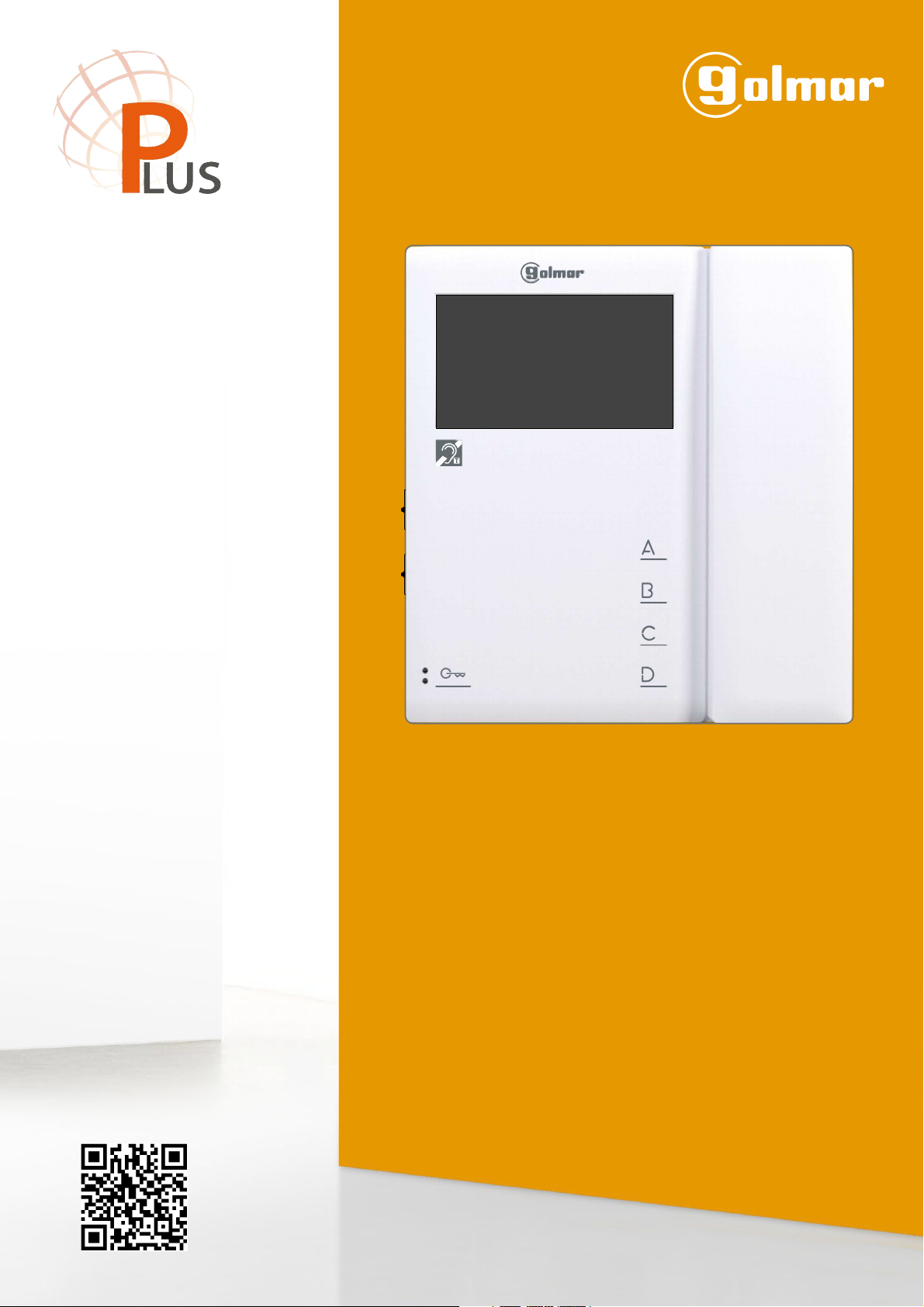
TEKNA-S PLUS
MONITOR
Code 50122251 T S ENTEKNA PLUS REV.0219
Page 2

TEKNA-S PLUS MONITOR
INTRODUCTION
First of all, we thank and congratulate you for purchasing this product manufactured by Golmar.
Our commitment to achieving the satisfaction of customers like you is manifested through our ISO-9001 certification
and the manufacture of products like the one you have just purchased.
Its advanced technology and strict quality control will ensure that customers and users enjoy the numerous features
that this device offers. To get the most out of them and ensure proper operation from day one, we recommend that you
read this instruction manual.
CONTENTS
Introduction....................................................................................................................................................................2
Contents........................................................................................................................................................................ 2
Safety precautions........................................................................................................................................... 2...............
Characteristics............................................................................................................................................................ .3.. .
System operation......................................................................................................................................... .3................. .
Description of the monitor.............................................................................................................................................. ...
Description
Monitor programming
Rapid monitor programming................................................................................................................... ............. 1......... . 1
Advanced programming (monitor functions)....................................................................................................... ..............
Men 1....................................................................................................................................................................... 1u 2
Activating/deactivating the doctor mode function
- .......................................................................................... ..... . .. 1.. . . 2.
- ........................................................................................................ ...... 1................... .. 2Changing the ringtone melody
Men 2....................................................................................................................................................................... 1u 3.
- ....................................................................................................................... 1..... 3
Changing the function of button
- .................................................................................................................... . 1...... . 3Changing the function of button
- .......................................................................................................................... . 1. 3.Intercom with TeknaPlus monitors
Men 3....................................................................................................................................................................... 1u 4.
Repeating the ringtones
- .......................................................................................................... ................ 1.................. 4.
- .......................................................................................... . 1.............. . 4.Adjusting the 'doorpanel communication time'
- ................................................................................................................ . 1............ 4Adjusting the 'door panel call' time
- ............................................................................................................................... . 1......... 4Activating the in-call video
Men 4....................................................................................................................................................................... 1u 5
Setting all of the monitor's advanced programming options to the 'default setting'
- .......................................... . 1........... . 5
Optional connections
- .................................................................................................................... .. 1. 6...................
Activating auxiliary devices
- ...................................................................... 1............. .. 6Input for auxiliary button to activate the door panel lock release
- ................................................................................................................. . 1.................. 7.Intercom within an apartment
- ........................................................................... . 1................. . 7.Button forreceiving calls from the apartment front door
- ............................................................................. .1............................................ ............. 8Activating a second camera
Cleaning the monitor
Wiring diagrams..................................................................................................................................... .1 -................. 9 20
Notes............................................................................................................................................................................21
Compliance..................................................................................................................................................................22
................................................................................................................................................................ .4.
............................................................................................. 4..Status LED and description of the connection terminals
............................................................................................................................................... .5..........Function buttons
............................................................................................................................. .. 5.Communication with hearing aids
.................................................................... ....................................................................................... 6.SW1 DIP switch
.......................................................................................... .................................. 6Description of the identification label
................................................................................ .............................. 7RJ-45 connector (installation with UTP cable)
.......................................................................................... ............................. 7End of line jumper and EL-562S module
.......................................................................................................8Installing the monitor in a wall mounting connector
....................................................................................... ............................ 9.Installing the monitor in an embedding box
............................................................................................................................. ......... 10........ . -11
............................................................................................................................................... .........
..................................................................................................................................... ........ .. 1.... . . 8
2
SAFETY PRECAUTIONS
- Avoid overtightening the screws of the monitor connector.
- Always disconnect the power supply before installing or making modifications to the device.
- The fitting and handling of these devices must be carried out by authorised personnel.
- All of the wiring must run at least 40cm away from any other wiring.
- Install the monitor in a dry protected location free from the risk of dripping or splashing water.
- Do not place in humid, dusty or smoky locations, or near sources of heat.
- Before connecting the device to the mains, check the connections between the door panel, power supply, distributors
and monitors.
- Always follow the instructions contained in this manual.
Page 3
TEKNA-S PLUS MONITOR
CHARACTERISTICS
- Monitor for Plus / Uno installation.
- 4.3” TFT colour screen.
- Monitor with 3 common wires plus coaxial cable.
- Monitor with 4 common wires plus twisted pair.
- Monitor with UTP cabling plus RJ-45 connector.
- Enables communication with hearing aids equipped with T-mode,making conversation possible (inductive loop).
- Function and advanced programmingbuttons (to customise the monitor's functions).
- Completely private conversation and image.
- Auto switch-on function.
- Auto spy function without occupying a channel.
- 'Doctor mode' function (automatic door opening, see p. 12).
- Intercom between two devices in the same apartment.
- Input for calls from the apartment front door.
- Call volume control (maximum, no volume 'night mode,' medium and minimum. See p. 5).
- Input for outside door release button.
- Output to auxiliary call repeater.
- Call to primary and secondary guard unit.
- Panic call to guard units.
- Different ringtones to identifycall origin: Door panel, guard unit, intercom and interior door of the apartment.
- Activation of two auxiliary functions: second camera, courtesy lights, etc.
- Control of brightness and colour.
- DIP switches for setting the monitor address, 'call code' and master/slave (quick programming mode).
- Door release button.
- Monitor status LED.
- Programming LED.
3
SYSTEM OPERATION
- To make acall, the visitor pressesthe button for theapartment, a number ofaudible tones indicate that thecall is being
made and LED on the door panel illuminates. At this moment, the apartment's monitor (telephone) receives the
call. If the visitor presses thebutton for another apartmentby mistake, thecall can be cancelled by pressing thebutton
for the correct apartment.
- In systems with several access doors, the other door panel(s) automatically disconnects; if another visitor attempts to
call, a number of telephone tones will indicate that the channel is busy and LED on the door panel will illuminate.
- General panels (EL501 mode): If the call is being made from the general entrance door panel, the interior door panel
of the building being called and other possible general entrance door panels automatically disconnect. If another
visitor attempts to call from either abusy interior door panel,a number of telephonetones will indicate thatthe channel
is busy and LED of the door panel will illuminate, or from another general entrance door panel, a number of
telephone tones will indicate that the channel is busy and LED of the general entrance door panel will blink for 3
seconds. The door panels of the other interior buildings will remain free to be used.
- General panels (EL501 mode): If the call is made from an interior panel, the other interior panels will remain free to be
used. It is only possible to make calls to interior buildings from the general entrance door panels when their door
panels are not in use. If an attempt is made to make a call to a busy interior door panel, a number of telephone tones
will indicate that the channel is busy and LED of the generalentrance door panel will blink for 3 seconds.
- The call lasts for 45 seconds, during which time an image appears on the apartment's monitors for 2 seconds after the
call is received without the visitor knowing, and the status LED on the master monitor will illuminate (green). If the call
is not answered within 45 seconds, the master monitor's status LED will illuminate (red), LED on the door panel will
turn off and the channel will become free.
- To establish communication, lift the handset of the monitor, and the monitor's status LED (green) and the door panel's
LED will illuminate. The handset enables communication with hearing aidsCommunication with hearing aid :
equipped with T-mode, making conversation possible (inductive loop).
- Communication will last for one and a half minutes or until the handset is hung up. After communication, the monitor's
status LED will illuminate (red), the door panel's LED will turn off and the channel will be free.
- To open the door, press the door release button during the call or communication processes: one press will activate
the door release for 3 seconds and LED on the doorpanel will also illuminate for 3 seconds.
- Adescription of the function buttons can be found on p. 5.
Page 4
TEKNA-S PLUS MONITOR
Ω
DESCRIPTION OF THE MONITOR
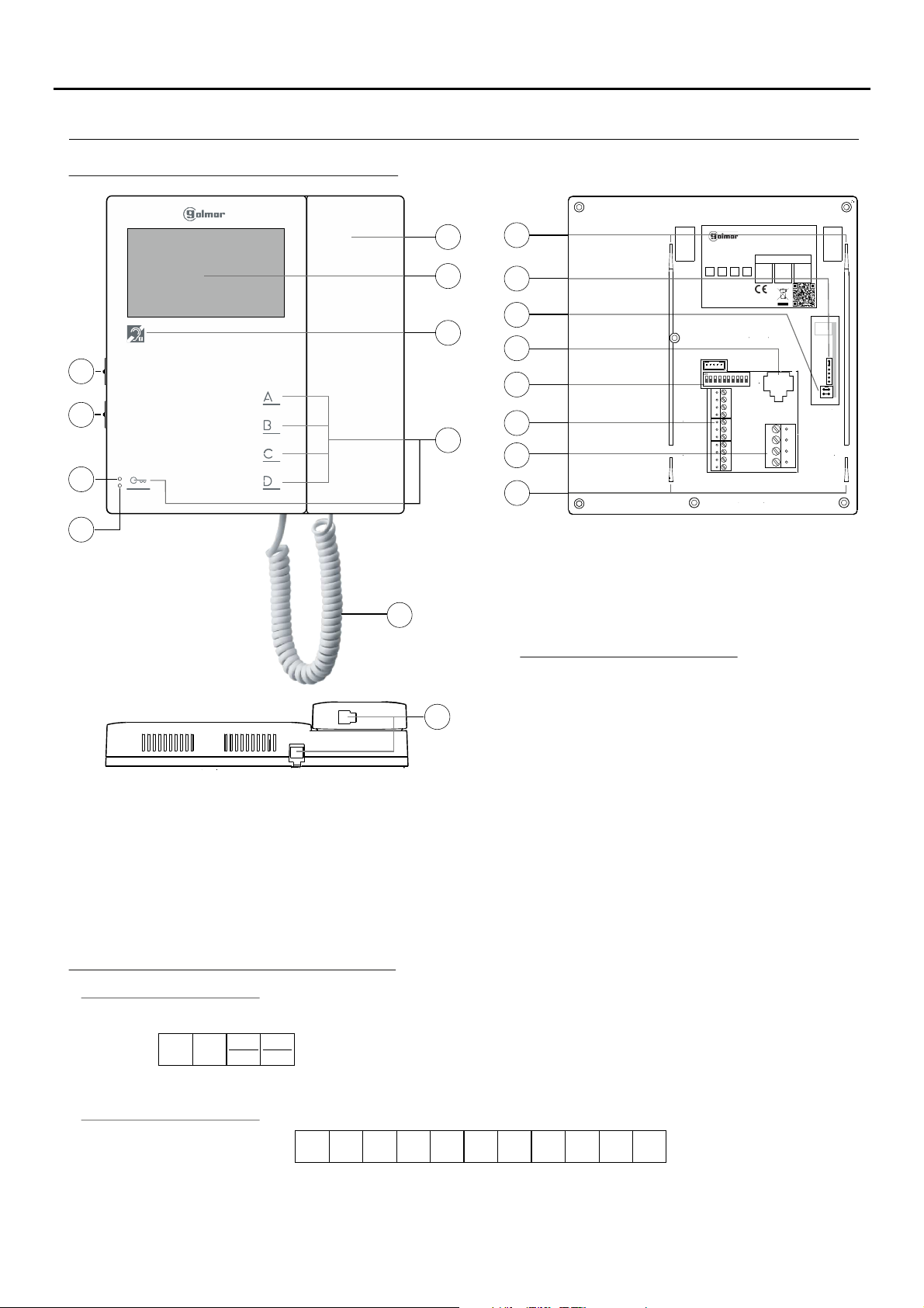
Description of the Tekna S Plus monitor:
4
g
h
i
j
a.
Handset.
b.
4.3” TFT colour screen.
c.
Communication with hearing aids. Set the
hearing aid switch to position T.
d.
Function/programming buttons.
e.
Telephone cord.
f.
Conector para cordón.
g.
Cord connector.
h.
Colour control.
a
b
k
l
15090200000SN ADDRESS
INTER A1 SLAVE MASTER
ATENCIóN
Altatensión. No abrir la tapa.
Manipularsólo por personal
delservicio técnico.
WARNING. GOLMAR S.A
HighVoltage. Don´t open cover C/Silici, 13
Handle only bytechnical service 08940 - SPAIN
TEKNA-S PLUS
11742126 V.XX
ESCALERA
PISO
PUERTA
STAIR
FLOOR
DOOR
m
c
d
n
q
o
p
1 2 3 4
SW1
5 6 7 8 9 10
CN2
CN3
CN4
75
JP1
k
e
i.
Advanced programming LED.
j.
Monitor status LED (two-colour):
- In standby: LED illuminated red.
- Call:LED illuminated green(mastermonitor).
- Communication: LED illuminated green.
f
- Auto spy if Bus busy:
LED blinking red rapidly.
- No volume (night mode):
LED blinking red.
- Doctor mode: LED blinking green.
k.
Connector fixings.
l.
CN4 connector (end of line jumper).
m.
JP1 jumper, remove in video installation with
twisted pair (see 'EL562S module' p. 7).
n.
RJ-45 connector (installation with UTP cable).
o.
SW1 configuration switches.
p.
CN2 connection terminals.
q.
CN3 connection terminals.
Description of the connection terminals:
CN3 connection terminals:
– :, +
_
+
Vin
MP
Vout
VP
Vin :
– :
Vout :
Vp, Mp :
CN2 connection terminals:
_
A D
A :
D :
HZ- :
AP+ :
INT :
Audio communication.
Digital communication.
Door bell button input.
Input for auxiliary door opening button.
Intercom function.
Negative, positive (18Vdc power supply).
Video signal input through coaxial cable.
Coaxial cable mesh.
Video signal output through coaxial cable.
Balanced video signal (through twisted pair).
_
-
HZ
AP+
INT
2C
A1 :
+ SA2C A1
Output for 2nd camera activation.
Output (negative) for auxiliary device
activation (max. consumption 50mA).
SA :
Output (negative) for auxiliary call
repeater (max. consumption 250mA).
Page 5
TEKNA-S PLUS MONITOR
DESCRIPTION OF THE MONITOR
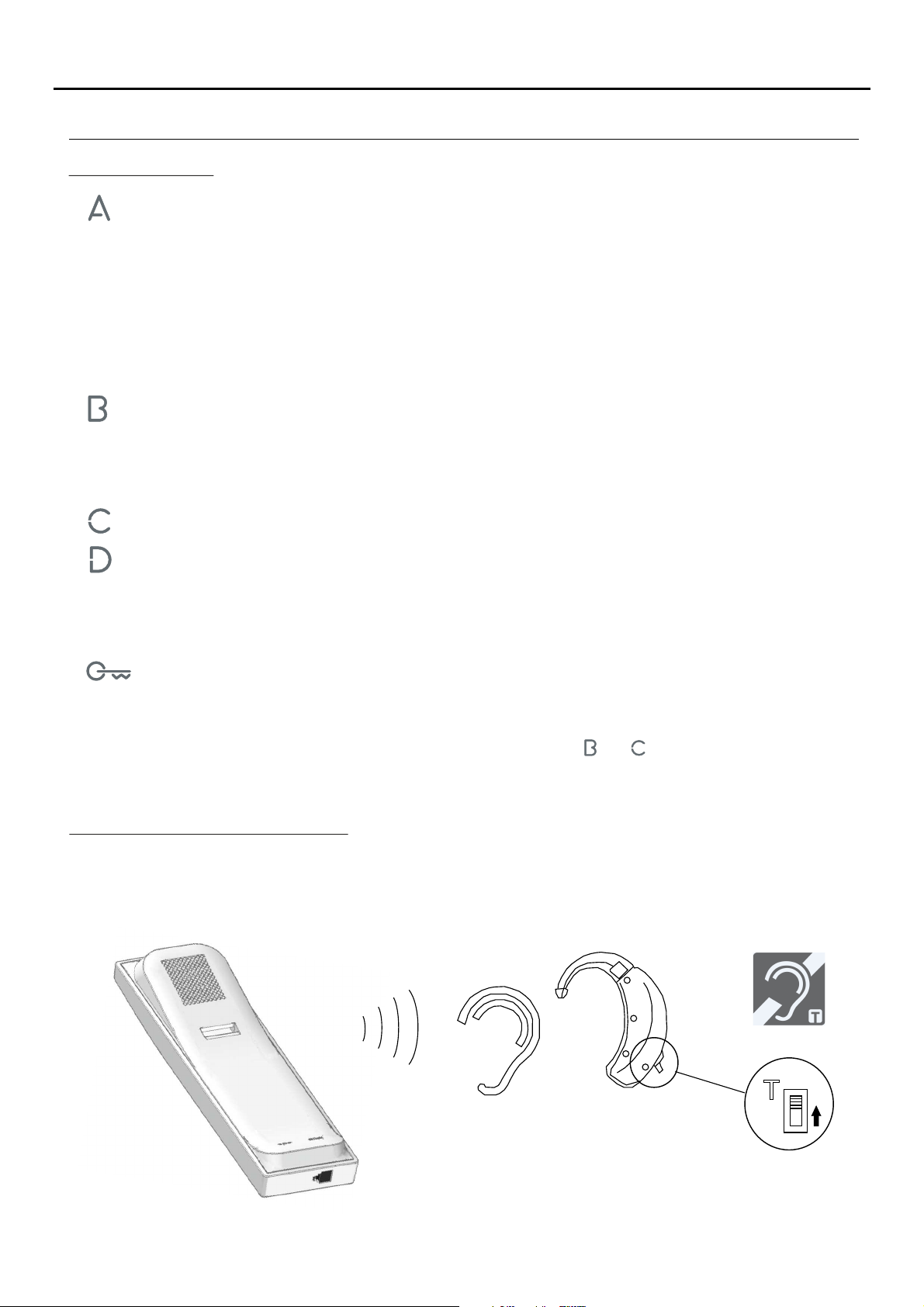
Function buttons:
One long press for 2 seconds: with the monitor in standby and the handset on the hook, this activates
ringtone volume mode, with a tone indicating the volume selected. Then each long 2-second press
(before 5 seconds elapse) selects a volume level: maximum, no volume 'night mode,' minimum and
medium, and so on (carousel mode). Note: The 'night mode' status LED blinks red. During a call, the
monitor does not emit a ringtone unless it is an 'apartment front door call.'
One long press for 3 seconds: with the monitor in standby and the handset on or off the hook, this turns the
monitor off. Then one short 1-second press turns on the monitor.After any resetting of the monitor and for
the following 45 seconds, no operation with it can be performed.
One long press for 3 seconds during a call cancels the call on the monitor. If there are more monitors in the
apartment, they will continue with the ringtones of the door panel. During communication with the door
panel, the communication in progress will end.
5
( )
*
( )
*
(*) In advanced programming mode, the default functions of function buttons and can be changed with one of the
With the monitor in standby and the handset off the hook, this activates the intercom function (in the same
apartment). One long press until a confirmation tone can be heard will call all of the monitors in the
apartment. To call individual devices, press the button once to call the 'master' monitor, twice to call 'slave
1,' 3 times to call 'slave 2,' 4 times to call 'slave 3' and 5 times to call 'slave 4.' This selective intercom call
mode is only available with Tekna Plus SE, Tekna HF Plus and Tekna S Plus monitors.This only functions
if no call or communication is in progress.
Regardless of the position of the handset, this activates auxiliary device 'A1.'
With the monitor in standby and the handset on the hook, this enables the image from the door panel
configured as main to be viewed (ifthe bus is busy, the status LED of the monitorwill indicate sowith a few
quick blinks). With the handset off the hook, this enables audio and video communication with door
panels that have their auto switch-on function activated to be established. This only functions if no
communication is in progress.
In call, a slave monitor enables the image of the door panel to be captured.
With the monitor in standby and the handset on the hook, this makes a panic call to the guard units
configured to receive such calls. With the handset off the hook, it enables a normal call to be made to the
main guard unit. During call reception and communication processes, it enables the lock release to be
activated.
following functions at the same time and per button: 'intercom,' 'auxiliary deviceA1 activation,' 'second camera 2C
activation' or 'call to secondary guard unit' (see p. 13).
Communication with hearing aids:
The handset of the Tekna-S monitor enables communication with hearing aids equipped with T-mode, makingPlus
conversation possible (inductive loop).
Remember: Set the hearing aid switch to position T.
T
Page 6
TEKNA-S PLUS MONITOR
SW1
1 2 3 4
5 6 7 8 9 10
CN2
CN3
DESCRIPTION OF THE MONITOR
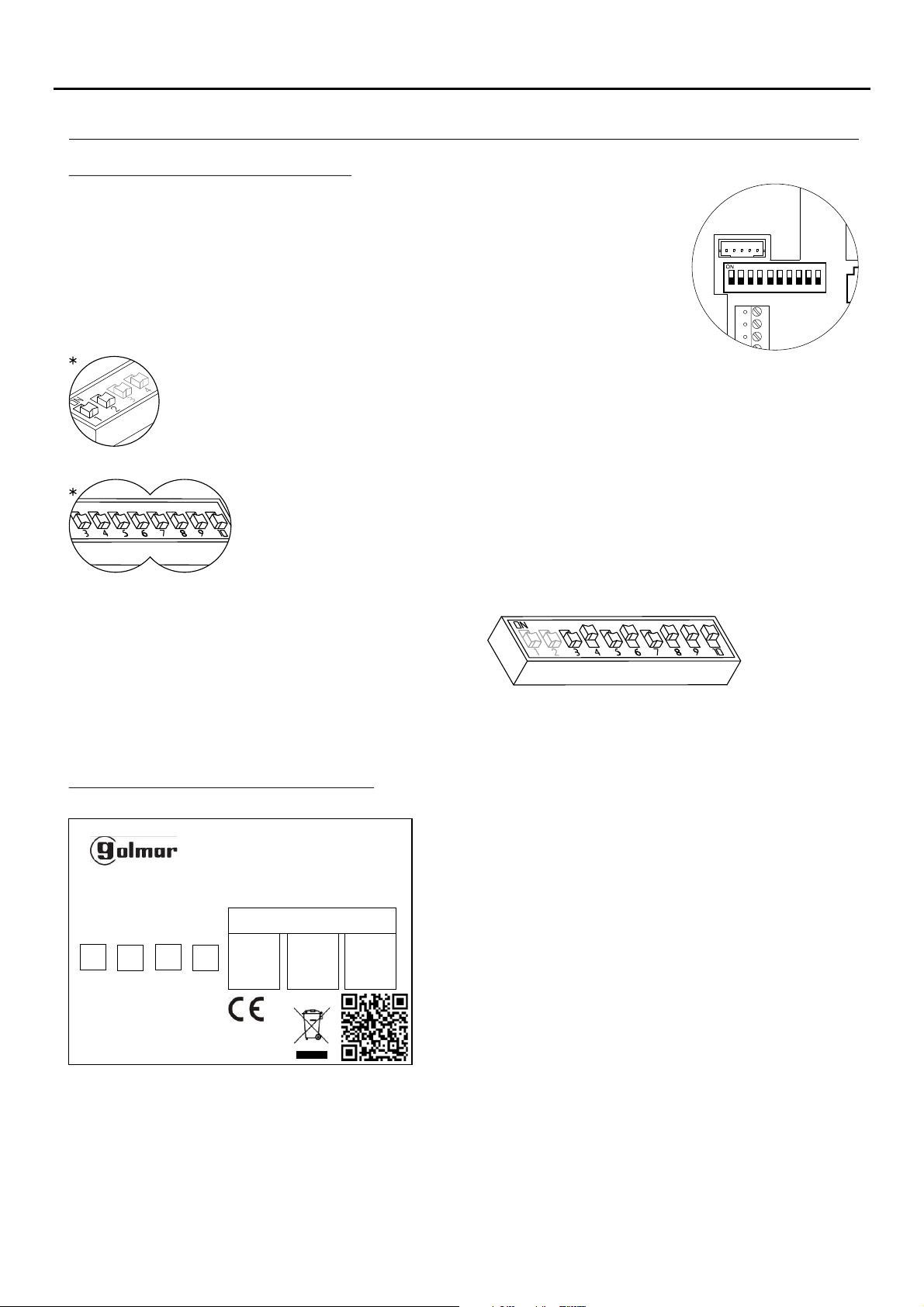
Description of the SW1 DIP switch:
The SW1 DIP switch is located at the back of the monitor on the right-hand
side. It enables the monitor to be configured as master/slave and an address
to be assigned.
Important: This type of programming cannot be performed on a general
entrance door panel.
DIP 1 and DIP 2: Sets the monitor as master/slave + intercom. DIP 1 and DIP 2 to OFF
master, DIP 1 to OFF and DIP 2 to ON slave 1, DIP 1 to ON and DIP 2 to OFF slave 2, DIP 1
and DIP 2 to ON slave 3.
DIP 3 to DIP 10: To set the monitor address (addresses 1 to 255). The switches set to OFF
have a zero value.
The values of the switches set to ON are shown in the table below.
The monitor code is the sum of the values of the switches set to ON.
6
Switch number:
Value when ON:
46453261678849210
3
128
*Factory setting
Description of the identification label:
TEKNA-S PLUS
11742126 V.XX
00000000000 SN ADDRESS
INTER A1 SLAVE MASTER
ATENCIóN
Alta tensión. No abrir la tapa.
Manipular sólo por personal
del servicio técnico.
WARNING. GOLMAR S.A
High Voltage. Don´t open cover C/ Silici, 13
Handle only by technical service 08940 - SPAIN
ESCALERA
STAIR
PISO
FLOOR
PUERTA
DOOR
1
Example: 64+0+16+0+4+2+1=870+
To facilitate repair, replacement or the addition of monitors to
the existing installation, fill in the label with the relevant
information.
MASTER: main monitor.
SLAVE: slave monitor.
INTER: secondary monitor with intercom function.
A1: monitor connected to an auxiliary device.
CODE: call button code.
STAIRWAY: code of the channel (building).
Page 7
TEKNA-S PLUS MONITOR
75
W
CN4
JP1
75
W
SW1
8 9 10
CN3
DESCRIPTION OF THE MONITOR
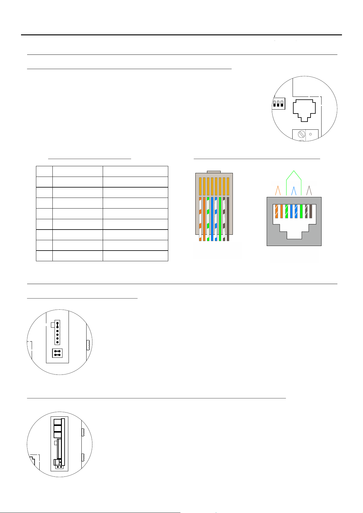
Description of the RJ-45 connector (installation with UTP cable):
The monitor features an RJ-45 connector for installation with a UTP cable. It is
located at the back of the monitor on the right-hand side.
It enables connection of the system's main communication wires
and Mp) .
in twisted-pair installations
(+, -, A, D, Vp
7
RJ-45 equivalence table
Pin
Ethernet cable
White + Orange
1
Orange
2
White + Green
3
Blue
4
White + Blue
5
Green
6
White + Brown
7
Brown
8
Golmar connection
GND (Audio)
Audio
GND (Data)
+18V
+18V
Data
Vp
Mp
MONITOR SETTINGS
Handling of the end of line jumper:
The end of line jumper is located on the CN4 connector at the back of the monitor on the
right-hand side.
In the case of twisted pair installations, the end of line jumper is located on the EL562S
module (see next section).
Do not remove the jumper if the video cable ends inthe monitor. Remove the jumper if the
video cable continues after the monitor.
RJ-45 connector (cable type: T568B)
PA R 3I
PA R 2I PA R 1I PA R 4I
1 2 3 4 5 6 7 8
1 2 3 4 5 6 7 8
Male connector Female connector
EL-562S module for video door entry system installations with twisted pair cable:
Locate the CN4 connector at the back of the monitor on the right-hand side.
To insert the EL-562S module, first remove the jumper located in the CN4 connector and
JP1 of the monitor.
NOTE: In this type of installation, set the SW1-3 DIP switch on the sound module of the
door panel to ON, see the instruction manual (p. 13) or set the SW1-3T632/Plus P/T
DIP switch of the EL500SE microprocessor to ON, see the manual (p. 7).T5000 ML
The door panel of the SV801SE GRF kit does not require modification.
Use the specific wiring diagram.
Page 8
TEKNA-S PLUS MONITOR
8
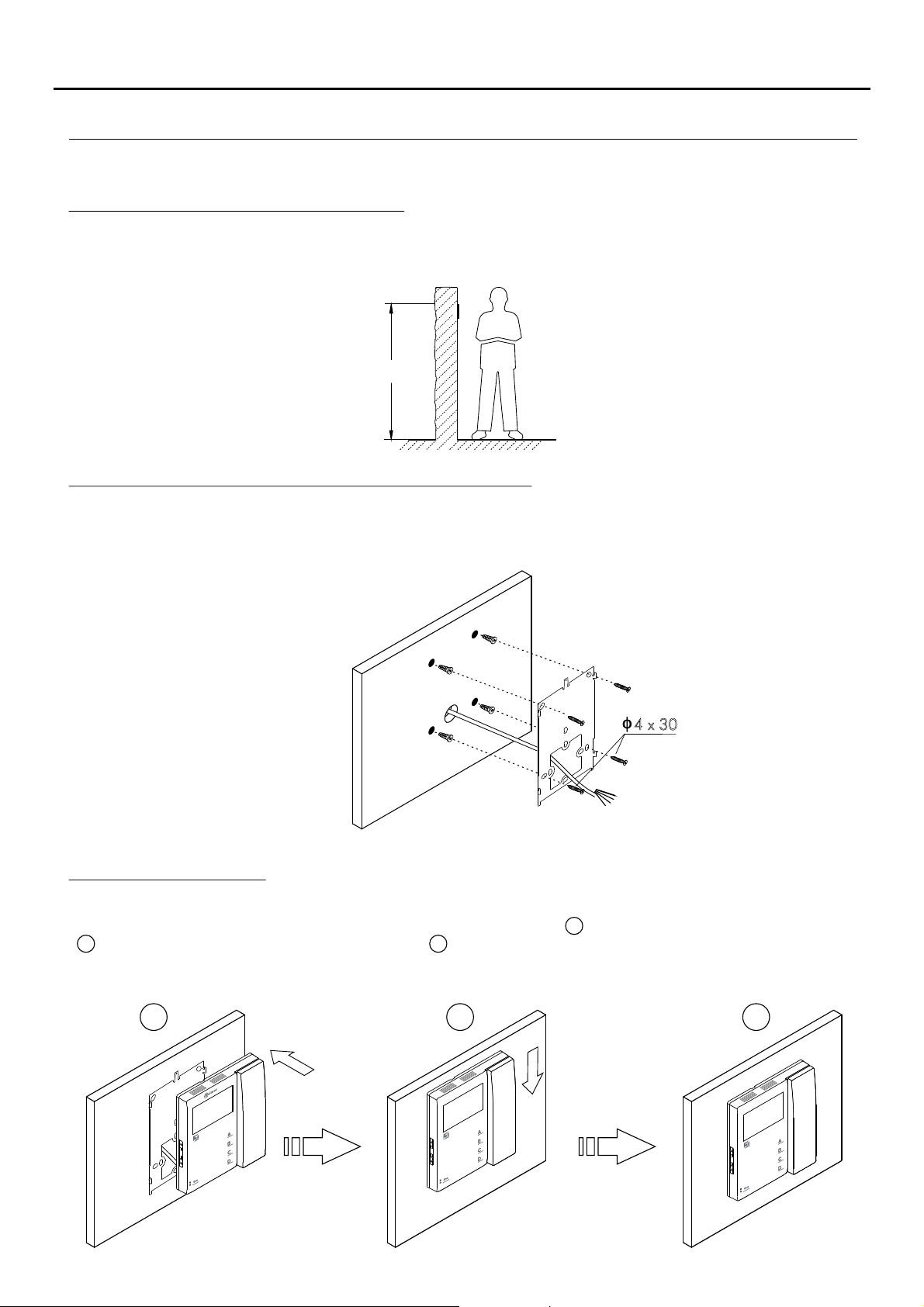
INSTALLING THE MONITOR IN A WALL MOUNTING CONNECTOR
Avoid dusty or smoky environments or locations near sources of heat.
E
Positioning the wall mounting connector:
The top of the connector must be positioned at a height of 1.60 m. The minimum distance between the sides of the
connector and the closest object must be 5 cm.
1 6. 0m
Fixing the monitor's wall mounting connector to the wall:
Fix the monitor's wall mounting connector to the wall by drilling two 6mm diameter holes and using the screws and plugs
supplied with the terminal.
x4 30
Positioning the monitor:
Connect the cables to the monitor (see p. 4), position the monitor in front of the wall mounting connector, ensuring that
the holes in the base of the monitor line up with those on the connector , and then move the monitor downwards
2
until the monitor is securely fixed to the connector .
Remember to remove the protective covering from the front of the monitor once installation is complete.
1
3
2 3
1
Page 9
TEKNA-S PLUS MONITOR
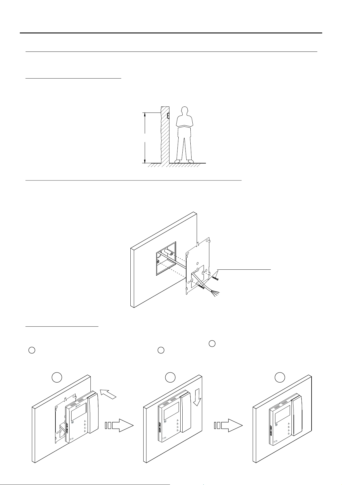
INSTALLING THE MONITOR IN AN EMBEDDING BOX
Avoid dusty or smoky environments or locations near sources of heat.
Location of the embedding box:
Make a hole in the wall to position the top of the universal embedding box at a height of 1.60 m from the ground. The
minimum distance between the sides of the embedding box and the closest object must be 5 cm.
1 6. 0m
Positioning the embedding box and fitting the wall mounting connector:
Pass the cable through the hole made in the embedding box. Embed the box and ensure that it is level and flush.
Fix the wall mounting connector of the monitor to the embedding box with the screws supplied.
9
Screws supplied with the
embedding box.
Positioning the monitor:
Connect the cables to the monitor (see p. 4), position the monitor in front of the wall mounting connector, ensuring that
the holes in the base of the monitor line up with those on the connector , and then move the monitor downwards
2
until the monitor is securely fixed to the connector .
Remember to remove the protective covering from the front of the monitor once installation is complete.
3
1
2 31
Page 10
TEKNA-S PLUS MONITOR
PROGRAMMING THE MONITORS
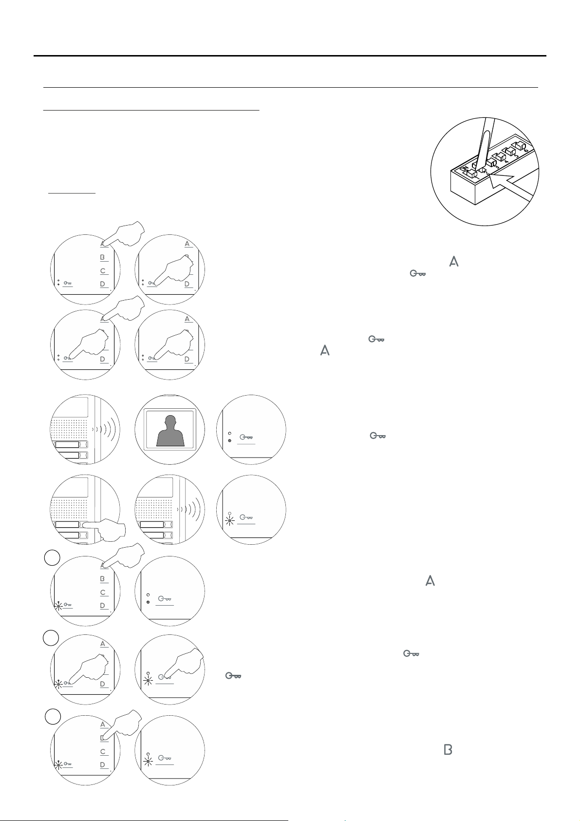
Programming the TEKNA S PLUS monitor:
Locate the SW2 DIP switch on the EL632 Plus sound module of the door panel or the
EL500SE microprocessor and set to ON.
In systems with more than one door panel, only perform thisprocedure on the main panel
of each building.
Important: To perform this programming, the monitor's SW1 DIP switch should be set to
OFF.
Turn off the monitor to be programmed (press button for 3 seconds).
Once switched off, press door release button .
10
M
Press and hold doorrelease button and, without releasing it, switch on the
monitor (press button for 1 second).
To show that the device is ready for programming, the door
panel and monitor will emit a number of tones (the status
LED on the monitor will illuminate red), enabling door
release button to be released. To establish audio
communication with the door panel, lift the handset.
Press the door panel button that will call this monitor.
At this moment, the door panel and monitor will emit a
number of tones (the status LED on the monitor will blink
red).
To programme the monitor as , press button for 3 seconds (themonitor'sMaster
LEDwill illuminate red).
S
SI
To programme it as , press button once and the status LED willSlave 1
blink (green) once. Continue successively to , pressing buttonSlave 4
four times and the status LED will blink (green) four times.
To programme it as , press button and the LED will blinkSlave + Intercom
(green) once.
Continued overleaf
Page 11
TEKNA-S PLUS MONITOR
SW1
1 2 3 4
5 6 7 8 9 10
CN2
CN3
PROGRAMMING THE MONITORS
Continued from previous page.
11
SV
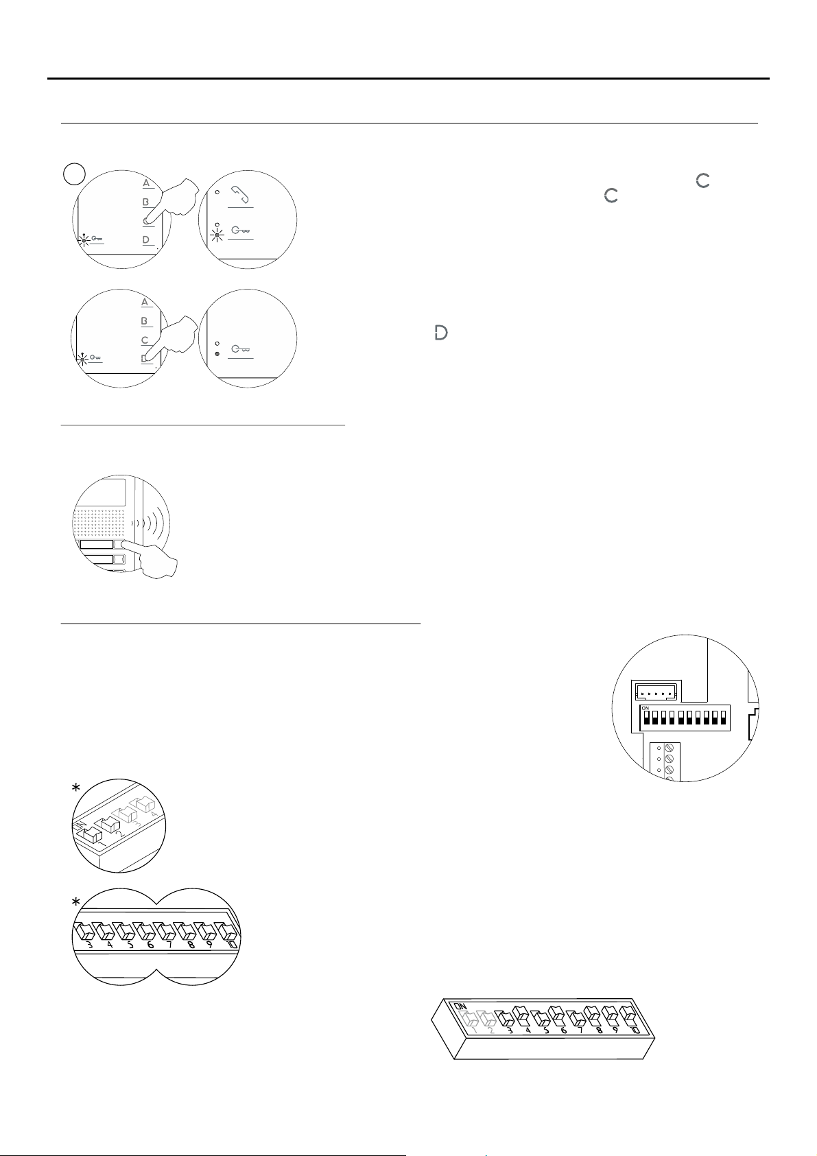
To programme it as (in call), press button and theSlave without video
status LED will blink (green) once. If button is pressed again, the
monitor will return to being programmed as (in call) andSlave with video
the status LED will blink (green) twice. The door panel video will be
displayed during a call if programmed to do so:
To exit, press button (the monitor's LED will illuminate red).
Each apartment must only have one master unit; if there are parallel units, either monitors or telephones, they must be
configured as slaves.
Make a call to check that the monitor has beensuccessfully programmed. Programme the other
monitors in the same way.
Once the programming has finished, set the programming switch to OFF. If this is not done, the
door panel will emit tones to indicate that the system is still in programming mode.
Quick programming of the Tekna S Plus monitors:
The SW1 DIP switch is located on the left-hand side of the back of the monitor.
It enables the monitor to be configured as master/slave and an address to be
assigned.
Important: This type of programming cannot be performed on a general
entrance door panel.
DIP 1 and DIP 2: Sets the monitor as master/slave + intercom. DIP 1 and DIP 2 to OFF
master, DIP 1 to OFF and DIP 2 to ON slave 1, DIP 1 to ON and DIP 2 to OFF slave 2, DIP 1
and DIP 2 to ON slave 3.
DIP 3 to DIP 10: To set the monitor address (addresses 1 to 255). The switches
set to OFF have a zero value.
The values of the switches set to ON are shown in the table below.
The monitor code is the sum of the values of the switches set to ON.
Switch number:
Value when ON:
*Factory setting
46453261678849210
3
128
1
Example: 64+0+16+0+4+2+1=870+
Page 12
TEKNA-S PLUS MONITOR
ADVANCED PROGRAMMING (MONITOR FUNCTIONS)
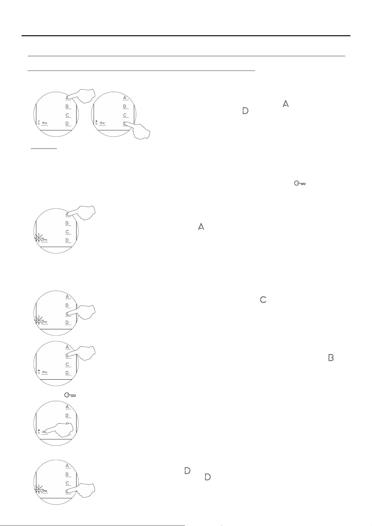
Advanced programming of the functions of the Tekna S Plus monitor:
Advanced programming enables the monitor's default settings to be changed:
Turn off the monitor to be programmed (press button for 3 seconds).
Once switched off, press button to access of advanced'Menu 1'
programming and the programming LED will illuminate.
Men 1:u
Then adjust the settings as required:
- Activating/deactivating the doctor mode function: Doctor mode not activated (default setting).
The 'doctor mode' function enables the lock release to be activated automatically 6 seconds after making a call
from the door panel without having to establish communication or press door release button . The call ends
after 20 seconds and the channel will become free.
(Only the master monitor should be configured with 'doctor mode').
12
To activate doctor mode: Press button and the programming LED will indicate with 2 blinks
that the function is activated (the status LED will blink green) or with 1 blink that the function
is deactivated.
- Changing the ringtone melody:
The monitor has different ringtones to identify the origin of the call. The melodies assigned by default to the
ringtones can be selected from among others available on the monitor.
Select the ringtone to be changed: Each press on button selects a ringtone which is
indicated with blinks (1 to 4 blinks) of the programming LED and in the following order: door
panel, guard unit, intercom call and 'HZ' apartment front door call. When the final selection
is reached, the following press returns the user to the first selection and 1 blink of the
programming LED (carousel mode).
Then select the melody for the ringtone (selected in the previous step) by pressing button until
therequired 'carouselmode' melody is heard.
- Button has no function.
No function.
- Accessing 'Menu 2' or exiting programming mode:
To access press button and the programming LED will blink twice.'Menu 2,'
To exit programming mode, press button for 3 seconds, and the programming LED will turn
off (see p. 15).
Continued overleaf
Page 13
TEKNA-S PLUS MONITOR
ADVANCED PROGRAMMING (MONITOR FUNCTIONS)
Continued from previous page.
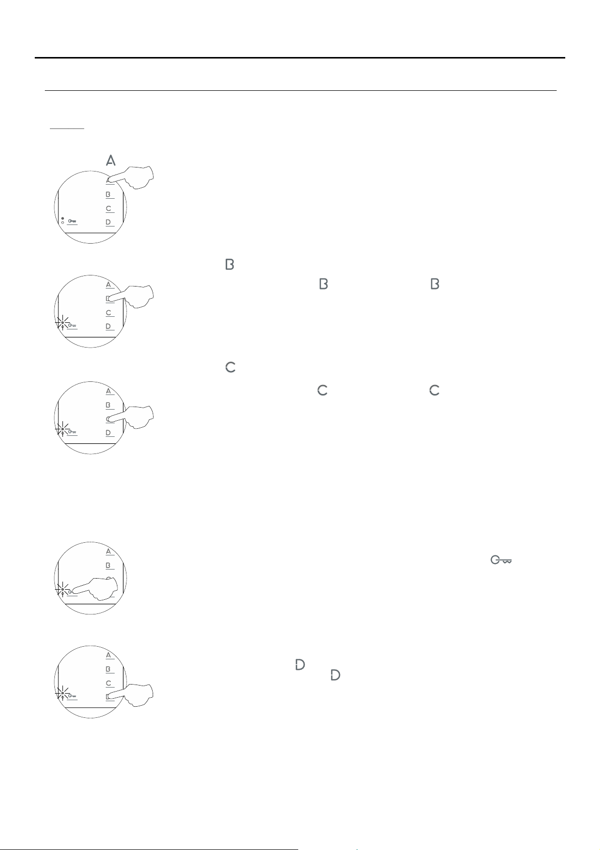
Men 2:u
Then adjust the settings as required:
- Button has no function.
No function.
- Changing the function of button : Intercom function (default setting).
Select the function to assign to button : Each press on button selects a different function
which is indicated with blinks (1 to 4 blinks) of the programming LED and in the following
order: auxiliary device 'A1' activation, call to secondary guard unit, second camera '2C'
activation and intercom. When the final selection is reached, the following press returns the
user to the first selection and 1 blink of the programming LED (carousel mode).
13
- Changing the function of button : Activation of auxiliary device 'A1' function (default setting).
Select the function to assign to button : Each press on button selects a different function
which is indicated with blinks (1 to 4 blinks) of the programming LED and in the following
order: auxiliary device 'A1' activation, call to secondary guard unit, second camera '2C'
activation and intercom. When the final selection is reached, the following press returns the
user to the first selection and 1 blink of the programming LED (carousel mode).
- Intercom with Tekna Plus monitors: Intercom with Tekna S Plus monitors (default setting).
If an apartment has Tekna Plus and Tekna S Plus monitors, the Tekna S Plus monitors should be configured with
'Intercom with Tekna Plus monitors' mode, as Tekna Plus monitors do not allow an intercom call to a particular
monitor in the apartment to be made (selective intercom call). So when an intercom call is made, all of the
monitors in the apartment will receive the call.
To activate the Intercom with Tekna Plus monitors mode: Press button , and the
programming LED will indicate with 1 blink that the function is in 'Intercom with Tekna Plus
monitors' mode or with 2 blinks that the function is in 'Intercom with Tekna S Plus monitors'
mode.
- Accessing 'Menu 3' or exiting programming mode:
To access press button and the programming LED will blink three times.'Menu 3,'
To exit programming mode, press button for 3 seconds, and the programming LED will turn
off (see p. 15).
Continued overleaf
Page 14
TEKNA-S PLUS MONITOR
ADVANCED PROGRAMMING (MONITOR FUNCTIONS)
Continued from previous page.
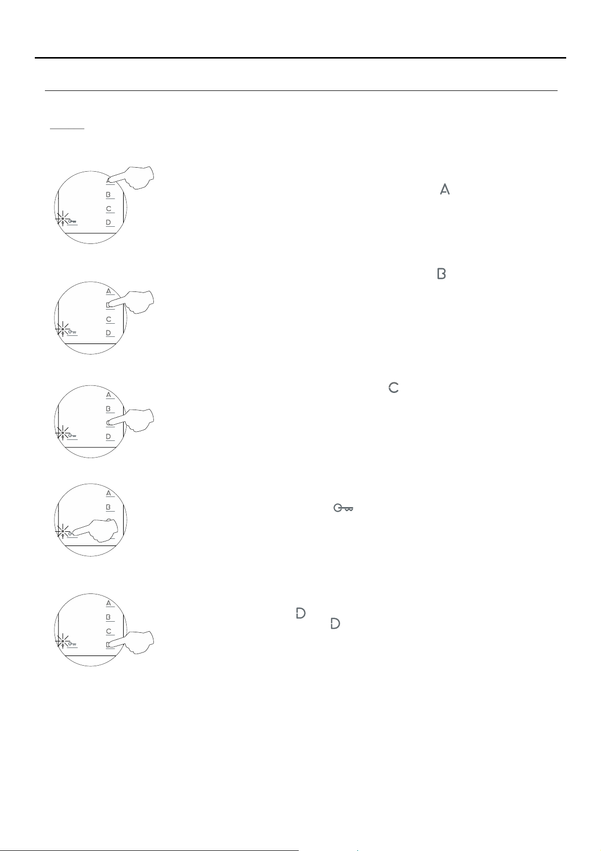
Men 3:u
Then adjust the settings as required:
- Repeating the ringtones: One repeat (default setting).
To 'repeat the ringtone' on the monitor: Each press on button selects a repeat of the
ringtones which is indicated with blinks (1 to 3 blinks) of the programming LED and in the
following order: 1, 2 or 3 repeats. When the final selection is reached, the following press
returns the user to the first selection and 1 blink of the programming LED (carousel mode).
- Setting the 'door panel communication time': 90 seconds (default setting).
To set the 'door panel communication time': Each press on button selects a communication
time which is indicated with blinks (1 to 4 blinks) of the programming LED and in the
following order: 60, 90, 120 and 150 seconds. When the final selection is reached, the
following press returns the user to the first selection and 1 blink of the programming LED
(carousel mode). This setting can be performed on Nexa door panels with the EL632Note:
Plus and EL632 Plus P/T sound module.
(Please consult our technical service department for information about other modelsof door
panel).
- Setting the 'door panel call' time: 45 seconds (default setting).
14
To set the 'door panel call' time: Each press on button selects a call time which is indicated
with blinks (1 to 4 blinks) of the programming LED and in the following order: 30, 45, 60 and
90 seconds. When the final selection is reached, the following press returns the user to the
first selection and 1 blink of the programming LED (carousel mode). This setting canNote:
be performed on Nexa door panels with the EL632 Plus and EL632 Plus P/T sound module.
(Please consult our technical service department for information about other modelsof door
panel).
- Activating the in-call video: The video appears when a call is received (default setting).
Activating the in-call video: Press button and the programming LED will indicate with 2
blinks that the video will appear on the monitor when acall is received or with 1 blink that the
video will appear at the end of the ringtone.
- Accessing 'Menu 4' or exiting programming mode:
To access 'Menu 4,' press button , and the programming LED will blink 4 times.
To exit programming mode, press button for 3 seconds, and the programmingLED will turn
off (see p. 15).
Continued overleaf
Page 15
TEKNA-S PLUS MONITOR
ADVANCED PROGRAMMING (MONITOR FUNCTIONS)
Continued from previous page.
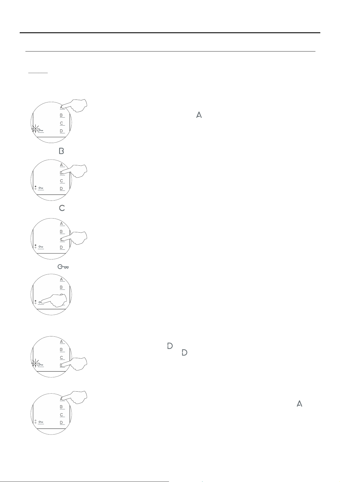
Men 4:u
Then adjust the settings as required:
- Setting to the 'default setting' all of the monitor's advanced programming options:
Setting to the 'default setting': Press button and the monitor will indicate with two audible
tones that all of the options of the monitor's advanced programming (pp. 12-15) are set to
their default setting.
- Button has no function.
No function.
15
- .Button has no function
No function.
- .Button has no function
No function.
- :Accessing 'Menu 1' or exiting programming mode
To access 'Menu 1,' press button , and the programming LED will blink once (see p. 12).
To exit programming mode,press button for3 seconds and the programming LEDwill turn off.
- Turning on the monitor when exiting programming:
When exiting advanced programming mode, the monitor will turn off: Press button for 1
second to turn on the monitor (the monitor's LED will illuminate red). After any resetting of
the monitor and for the following 45 seconds, no operation with it can be performed.
Page 16
TEKNA-S PLUS MONITOR
OPTIONAL CONNECTIONS
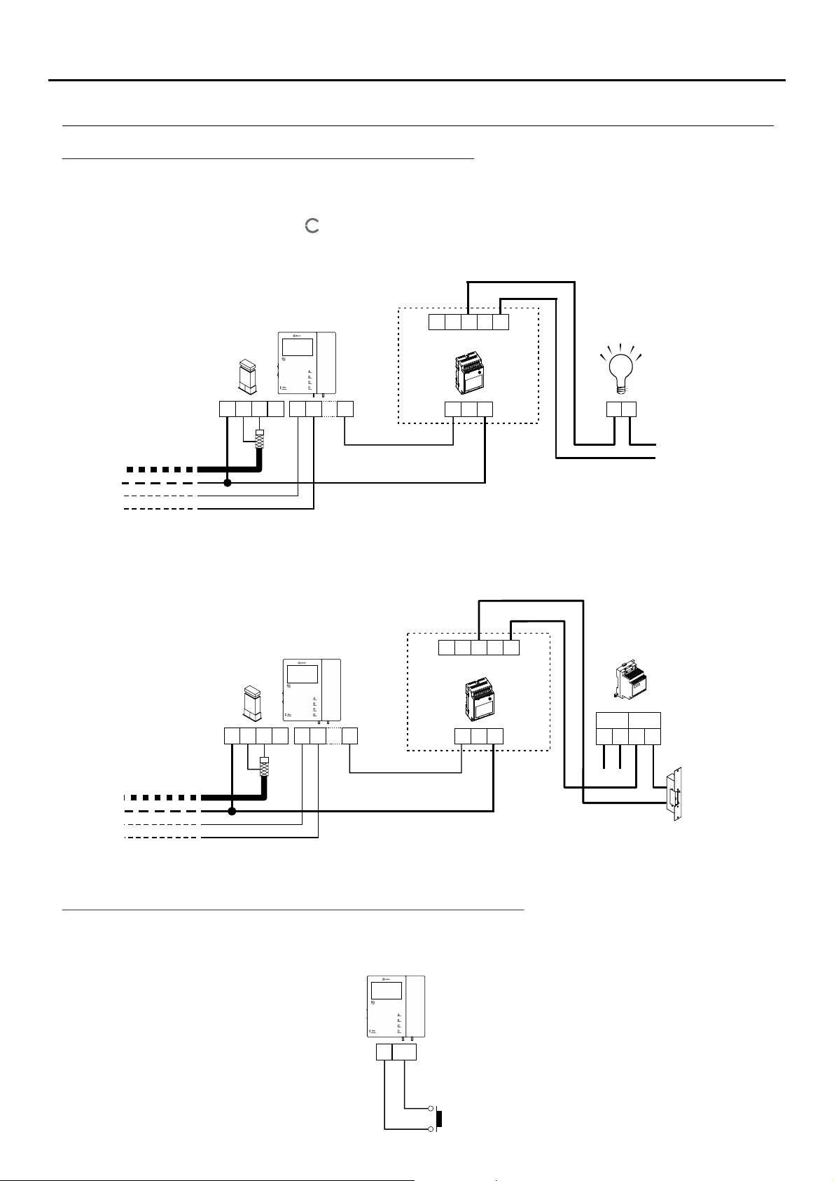
Activating auxiliary devices with Tekna S Plus monitors:
Auxiliary device activation requires the use of an SAR-12/24 relay unit. If the feature is shared by all monitors,
connect their A1 terminals; if, however, each monitor has its own feature, use an SAR-12/24 relay for each one
and do not connect theirA1 terminals.
This function is activated when button is pressed on the monitor at any time and regardless of the position of the
handset.
The most common applications are activating the stairway lights and opening a second door.
16
Tekna S Plus
CN4
_
V
V
+
CN3
To the distributor/
door panel.
( )
*
The neutral of the lighting power supply is arranged serially through the contacts of the SAR-12/24 relay and the
A
out
in
A1
D
CN2
NC NA C
SAR-12/24
IN IN
To the stairway light
activation button
F
220 Vac/
1.8A max.
N
( )
*
maximum consumption of the element to be connected does not exceed 1.8A.
To activate a second lock release, a TF-104 transformer is required.
NC NA C
SAR-12/24
IN IN
T 104F-
PRI
~~ ~~
Mains
SEC
*
To the distributor/
door panel.
CN4
CN3
Tekna S Plus
_
V
V
+
A
out
in
A1
D
CN2
Vac lock
release
Important: Place the varistor supplied with the sound module directly onto the terminals of the
*
lock release.
Input for outside button to activate the door panel lock release:
This enables the door panel lock release to be activated during a call or communication with the door panel.
With the monitor in standby, it makes a panic call to the guard units configured to receive such calls.
Tekna S Plus
_
AP+
CN2
AP
Continued overleaf
Page 17
TEKNA-S PLUS MONITOR
OPTIONAL CONNECTIONS
Continued from previous page.
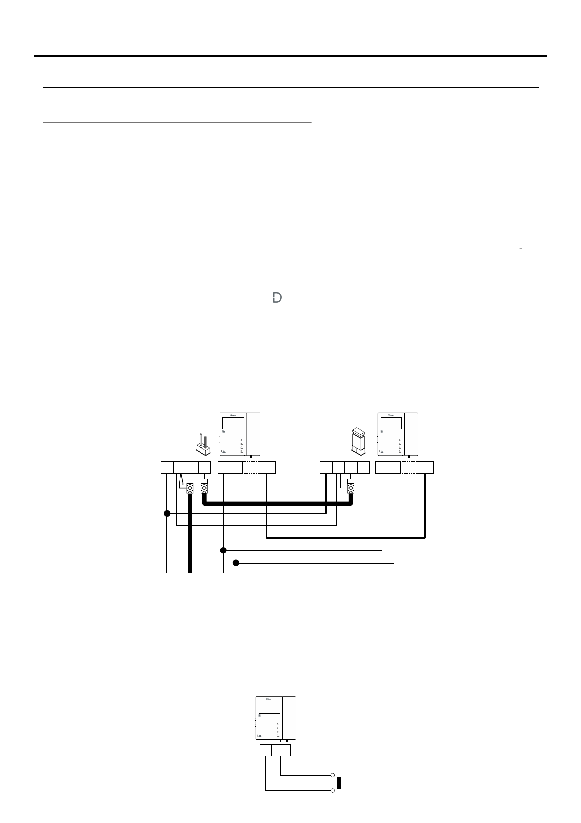
Intercom between two points in the same apartment:
The Tekna S Plus monitor features as standard an intercom function between two points in the same apartment.To
enable this function, the following is necessary:
- One of the monitors needs to be configured as master and the other as slave with intercom, as described on p.
10. In the case of intercom between a monitor and a telephone, it is recommended to configure the monitor as
the master.
- The INT terminals of the intercom devices need to be joined (see diagram below).
To use the intercom function to call all of the monitors in the apartment, lift the handset and press the button until a
confirmation tone can be heard. To call individualdevices, press the button onceto call the 'master' monitor, twice
to call 'slave 1,' 3 times to call 'slave 2,' 4 times to call 'slave 3' and 5 times to call 'slave 4.' This selective intercom
call mode is only available with Tekna S Plus, Tekna HF Plus and Tekna Plus SE monitors. This only functions if
no call or communication is in progress. A number ofaudible tones emitted by the handset will confirm that the call
is being made or that the unit being called is in communication with the door panel. To establish communication,
lift the handset of the unit being called. If a call is received from the door panel during an intercom process, the
handset of the master unit will emit a number of audible tones and an image will appear; to establish
communication with the door panel, press button on the unit configured as master or press the door release
button to simply open the door.
The ringtones vary depending on where the call is being made from, enabling the user to identify its origin.
Remember: If the apartment also has Tekna Plus monitors, the Tekna S Plus, Tekna HF Plus and Tekna Plus SE
monitors must be configured as 'Intercom with Tekna Plus monitors' (see p. 13). This configuration mode does
not allow selective intercom calls to different monitors in the apartment; when the intercom button is pressed, all
of the monitors in the apartment will receive the call.
17
V
V
out
in
Tekna S Plus
A
D INT
CN2
CN3
+
CN4
_
V
V
out
in
Tekna S Plus
D INT
A
CN2
CN3
+
CN4
_
Button for receiving calls from the apartment front door:
The Tekna S Plus monitorfeatures as standardthe ability toreceive calls fromthe apartment frontdoor. This feature
precludes the need to use the bell by positioning a button between terminals 'HZ—' and '—' of the monitor.
The ringtones vary depending on where the call is being made from, enabling the user to identify its origin. If a call is
made from the apartment front door during a conversation with the door panel, the handset will emit a number of
tones to indicate so.
Note: Regardless of the volume set for the monitor's ringtones (see p. 5) and the 'night mode' function, the
'apartment front door call' ringtone will always sound at the highest level.
Tekna S Plus
-
HZ-
CN2
Continued overleaf
Page 18
TEKNA-S PLUS MONITOR
OPTIONAL CONNECTIONS
Continued from previous page.
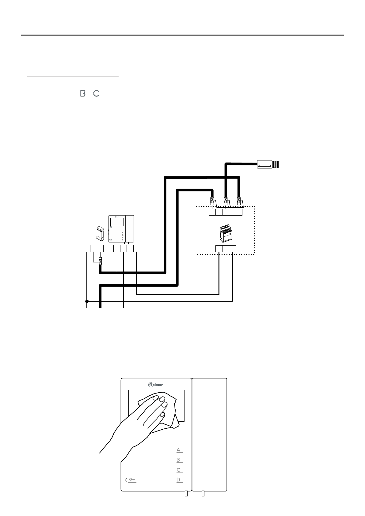
Activating a second camera:
To activate a second camera, it is necessary to use an SAR-12/24 relay unit and to change the configuration of
function button or on the monitor,as described on p. 13.
To activate this function, press the button configured for this function on the monitor during an auto-spy, call or
communication process.
If the feature is shared by all monitors, join their 2C terminals; if, however, each monitor or a group of monitors has
its own camera, use an SAR-12/24 relay for each one and do not connect the 2C terminals of the different groups.
This function can be used to activate anything else, as describedin the section on activation ofauxiliary devices, but
through the 2C terminal.
The most common applications could be to monitor access to the lift, to the entrance hall, etc.
2nd camera
18
CN3
CN4
+
Tekna S Plus
_
V
V
out
in
D
A
2C
CN2
NC NA C
SAR-12/24
IN IN
CLEANING THE MONITOR
- Do not usesolvents,detergents or cleaning products that contain acids, vinegar or abrasive components.
- Use a soft damp lint-free cloth with water.
- Always wipe the monitor in the same direction, from top to bottom.
- After cleaning the monitor,remove any moisture with a soft dry lint-free cloth.
Page 19
TEKNA-S PLUS MONITOR
WIRING DIAGRAMS
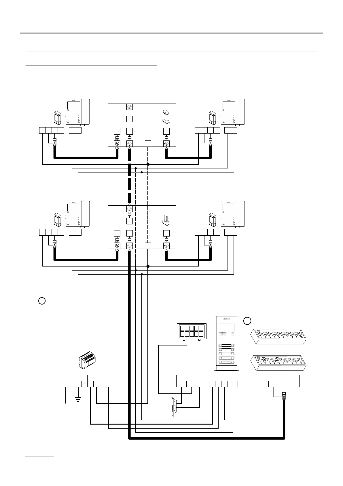
Video door entry system with coaxial cable:
Remove the JP1 jumper from
all of the distributors except
Tekna S Plus Tekna S Plus
the last.
19
D4L-PLUS
CN3
CN3
+
+
CN4
_
CN4
_
V
V
out
in
Tekna S Plus
V
V
out
in
S
D
A
CN2
D
A
CN2
D1
D1
E
S
E
JP1
D2
+
D4L-PLUS
JP1
D2
+
CN3
CN3
+
+
CN4
_
CN4
_
V
V
out
in
Tekna S Plus
V
V
out
in
D
A
CN2
D
A
CN2
M =Master.
Place this power supply as
close as possible to the
first distributor.
FA-Plus/C or FA-Plus
PRI
~~
Mains
SEC
+ +
CN3
9
10
1
--
DC lock
release
6
837
4
5
2
-
D
+-+CV1CV2
CN1
M
Vin-AinAout Vin+ Vout-Vout+
Mesh
SW2
SW1
Important:
For further information about the door panel, sections, distances, wiring diagrams, etc., see the T632 PLUS P/T manual.
https://doc.golmar.es/search/manual/50122328
Page 20
TEKNA-S PLUS MONITOR
WIRING DIAGRAMS
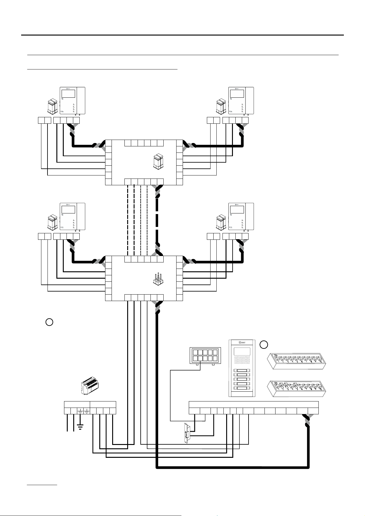
Video door entry system without coaxial cable:
Tekna S Plus Tekna S Plus
20
CN2
CN2
EL562S
JP1
A D
EL562S
JP1
A D
_
VpM
+
p
CN3
Tekna S Plus
_
VpM
+
p
CN3
* Remove the JP1 jumper
from all of the distributors
except the last.
_
V
M
V
CT
M
V
CT
d1
d1
+
_
D
d1
d1
+
_
D
_
+
_
_
+
A D+
AAD
A D+
AAD
M
po
JP1
V
M
pi
V
M
po
JP1
V
M
pi
D6L-Plus/2H
M
po
V
CT
pi
D6L-Plus/2H
M
po
V
CT
pi
EL562S
JP1
_
A D
CN2
d6
d6
+
_
VpM
+
p
CN3
A
D
Tekna S Plus
EL562S
JP1
_
A D
CN2
d6
d6
+
_
A
D
VpM
+
p
CN3
M =Master.
*Place this power supply
as close as possible to
the first distributor.
FA-Plus/C or FA-Plus
PRI
~~
Mains
SEC
+ +
CN3
9
10
1
--
DC lock
release
6
837
4
5
2
-
D
+-+CV1CV2
CN1
M
Vin-AinAout Vin+ Vout-Vout+
Mesh
SW2
SW1
Important:
For further information about the door panel, sections, distances, wiring diagrams, etc., see the T632 PLUS P/T manual.
https://doc.golmar.es/search/manual/50122328
Page 21

TEKNA-S PLUS MONITOR
NOT S:E
21
Page 22
TEKNA-S PLUS MONITOR
COMPLIANCE
Este producto es conforme con las disposiciones de las Directivas Europeas aplicables respecto a
la Seguridad eléctrica y la Compatibilidad Electromagnética .2014/35/CEE 2014/30/CEE
This product meets the essentials requirements of applicable European Directives regarding
Electrical Safety Electromagnetic Compatibility .20 / 5/ECC 20 4/ 0/ECC14 3 1 3,
El funcionamiento de este equipo está sujeto a las siguientes condiciones:NOTA:
(1) Este dispositivo no puede provocar interferencias dañinas, y (2) debe aceptar cualquier
interferencia recibida, incluyendo las que pueden provocar un funcionamiento no deseado.
Operation is subject to the following conditions:NOTE:
(1) This device may not cause harmful interference, and (2) this device must accept any
received interference, including the ones that may cause undesired operation.
22
Sistemas de comunicaciónS.A.
www.golmar.es
GOLMAR S.A.
C/ Silici, 13
08940- Cornellá de Llobregat
SPAIN
Golmar se reserva el derecho a cualquier modificación sin previo aviso.
Golmar se réserve le droit de toute modification sans préavis.
Golmar reserves the right to make any modifications without prior notice.
 Loading...