

Page 1
T-540 PLUS rev.0112
Digital
telephone Plus
system
Quick Guide
T-540 Plus
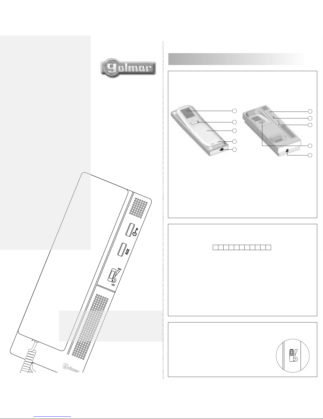
Description T-540 Plus telephone.
a
d
c
e
b
g
e
a.
b.
c.
d.
e.
f.
g.
h.
i.
Telephone handset.
Speaker grille.
Microphone hole.
Subjection hole.
Telephone cord connectors.
Door release push button.
Hook switch.
Auxiliary function push button.
Volume control.
Terminal connector description.
f
h
i
Positive, ground.
Audio, digital communication.
Connection to external door release push button.
Door bell push button input.
Auxiliary call device output SAV-90.
Intercom.
Output for aux. relay activation (18Vdc/0,5A max.)
+, - :
A , D :
Al :
HZ :
SA :
INT :
PA :
MAX
OFF
The telephone allows to regulate the call volume
with a maximum, medium and off value.
DESCRIPTION
1
Notes: Installation diagrams, see door panel manual.
Digital telephone for Plus system with door panel push button and
coded panel.
Call volume
control.
+ _ A D Al _ HZ SA + Int PA
Page 2
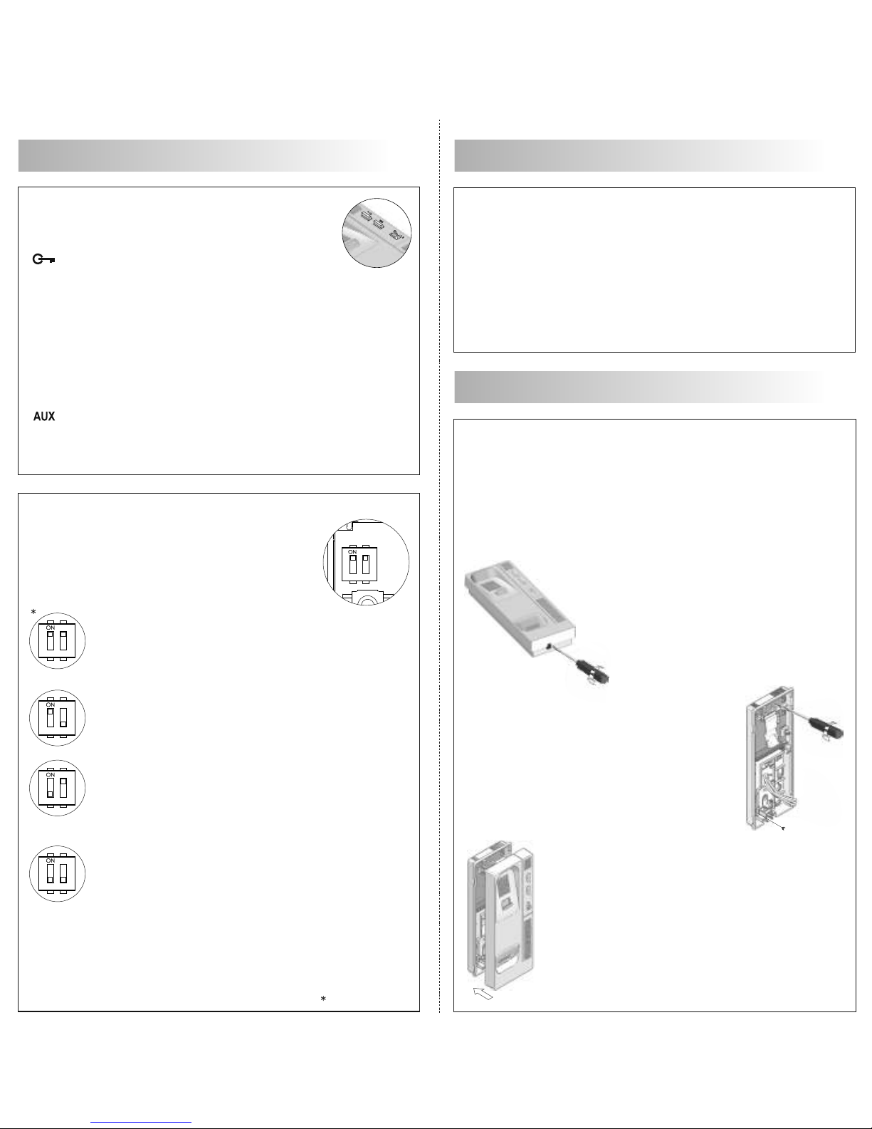
"Autoswitch-on" mode: With the handset off the cradle,
allows to stablish audio communication with the door
panel that has been configured with the autoswitch-on
function.
"PA" output mode: regardless of the handset's
position, it activates the "PA" telephone output.
"Call to a slave porter's exchange" mode: With the
handset off the cradle, allows to call to a slave porter's
exchange.
"Intercom" mode: With the handset off the
cradle, allows
to make an intercom call between two units of the same
apartment.
Function push buttons.
With handset on the cradle: sends a panic call to the
porter's exchanges.
With handset off the cradle: allows to call to the master
porter's exchange. During call reception and communication
progresses allows the lock release activation.
Auxiliary function push button, depending on setting in the
SW1 dip switch.
P3
SW1
1 2
1 2
1 2
1 2
1 2
SW1 configuration dip switch.
Accessed by opening the telephone, allow the
next modes for the auxiliary function push button:
Fix the telephone to the wall.
To install the telephone directly over the wall, drill
two holes of 6mm. on the specified positions,
using 6mm. wall plugs and Ø3,5 x 25mm
screws.
OPERATION
DESCRIPTION
IMPORTANT: Select the auxiliary function push button mode
before programming the telephone.
Factory default
Avoid placing the telephone near sources of heat, in dusty locations
or smoky environments. The telephone can be fixed using an
electrical embedding box or directly on the wall.
INSTALLATION
To open the telephone, insert a plain
screwdriver into the slots and gently lever
as shown in the drawing.
Pass the installation wires through the corresponding
hole and connect them. Close the telephone as
shown on the
picture. Once the telephone is
closed, connect the handset using the telephone
cord and put it on the cradle.
2
Receiving calls: While the call is in progress, pick up the telephone
handset to stablish audio communication for one and a half minutes
or until the handset is replaced.
Door release: During call or communication progresses, press the
door
release push button to allow the visitor acces to the building.
Page 3
P3
1 2
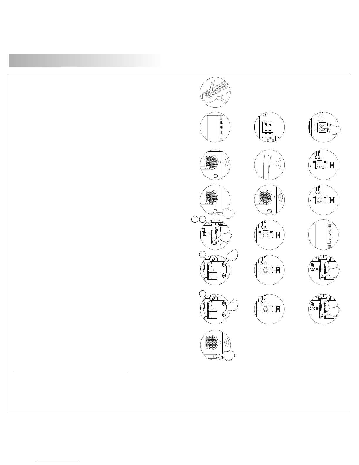
To show that the system is ready for programming, the door panel
and the telephone's handset will reproduce a tone (the telephone led
will light). Audio communication can be established.
Press the door panel push button that will call to this telephone, door
panel and
handset will reproduce tones (the telephone led will slow
blink).
P3
ON
To programm the telephone as Master, press the hook switch (the
telephone led will off). Close the telephone.
P3
ON
P3
ON
Set to ON the switch number 2 of the SW2 configuration dip switch
in the EL500SE (SW1 if it is the EL500) module.
Each apartment must have one master unit only; in case of parallel
units configure them as slaves, both monitors or telephones.
Make a call to check that the telephone has been succesfully
programmed. Once the programming has been finished, set to OFF the
programming switch.
To programm the telephone as Slave, press the P1 door release push
button (the telephone led will quick blink) and later press the hook
switch (the telephone led will off). Close the telephone.
P3
ON
P3
SW1
1 2
Open the telephone to programming, select in the SW1 dip switch the
function mode for the auxiliary function push button (page 2) and later
press the P3 programming push-button.
P1P2CN1
To programm the telephone as Slave + intercom., press the P2
auxiliary function push button (the led will quick blink) and later press
the hook switch (the led will off). Close the telephone.
M
S
SI
P1P2CN1
P3
SW1
P1P2CN1
ON
P3
ON
P3
SW1
P1P2CN1
ON
P3
SW1
P1P2CN1
ON
Telephone programming with a coded panel or from a general door
panel, see the appropiate door panel instruction book.
PROGRAMMING
P
3
Programming telephone with
door panel push button.
Page 4

1095 Budapest, Mester utca 34.
Tel.: *218-5542, 215-9771, 215-7550,
216-7017, 216-7018 Fax: 218-5542
Mobil: 30 940-1970, 30 959-0930
E-mail: [email protected] Web: www.delton.hu
www.golmar.hu
1141 Budapest, Fogarasi út 77.
Tel.: *220-7940, 220-7814, 220-7959,
220-8881, 364-3428 Fax: 220-7940
Mobil: 30 531-5454, 30 939-9989
 Loading...