

Page 1

99
RÉSOLUTION DES PROBLÈMES
Stadio Plus
Instructions manua
l
Audio and Video
door entry system
digital installation
(One or several
accesses doors /
General door panel)
Une façon simple de vérifier si les équipements fonctionnent correctement, est de les déconnecter de
l'installation et de les tester directement sur le circuit microprocesseur EL500SE.
Un court-circuit entre les différentes bornes (ou fils) n'endommagera jamais les équipements connectés,
à l'exception d'un court-circuit entre les bornes CTO et '–' du moniteur ou du distributeur .
O Rien ne fonctionne.
w Vérifier la tension de sortie entre les bornes '–' et '+' de l'alimentation. Celle-ci doit être comprise
entre 17,5 et 18,5Vc.c. Si ce n'est pas le cas, déconnecter l'alimentation de l'installation et
mesurer la tension. Si celle-ci est correcte, déconnecter l'alimentation du réseau
220/230Vc.a. et vérifier l'installation (possibilité d'un court-circuit).
w Vérifier que la borne 'D' ne soit pas en court-circuit avec les bornes '–' ou '+'.
w Vérifier que les bornes 'D' et 'A' n'aient pas été inversés dans le câblage.
O Le volume audio n'est pas satisfaisant.
w Régler le niveau comme expliqué page 67. En cas d'effet Larsen, réduire le volume jusqu'à
disparition de celui-ci. Si l'effet Larsen disparaît seulement lorsque le volume est au
minimum, il est possible qu'il y ait un autre problème.
O Effet Larsen persistant.
w Vérifier que la borne 'A' ne soit pas en court-circuit avec une autre.
O La commande de gâche ne fonctionne pas.
w N'oubliez pas que cette fonction ne peut être activée qu'après un appel ou durant une communication.
w
O Impossible de programmer le système.
w Vérifier que il a (page 63) et
que la séquence de programmation soit correcte.
w Vérifier que la borne 'D' ne soit pas en court-circuit avec une autre.
O Certains moniteurs (ou postes) ne reçoivent pas l'appel.
w Vérifier qu'un et un seul moniteur (ou poste) soit programmé comme principal. Vérifier que le
moniteur (ou poste) soit bien programmé et allumé.
w Les bornes CV1 et CV2 pour l'ouverture de la porte sont une sortie libre de potentiel et il faut
brancher le câblage selon le besoin, 12Vc.c.(page 83 à 94) ou 12Vc.a.(page 82).
Réalisez un court-circuit entre les bornes 'CV1' et 'CV2' du circuit microprocesseur EL500SE; à
cet instant, il devrait y avoir 12V (c.c. ou c.a. en fonction du type de gâche installé) entre les
bornes de la gâche.Si tel est le cas, vérifiez l'état de la gâche.
les micro-interrupteurs de configuration SW2 le switch nº 2 sur ON
Cod. 50124509
T500SE M
L
rev.0111
Page 2

102101
SAFETY PRECAUTIONS
INTRODUCTION
STARTING RECOMMENDATIONS
INDEX
First of all we would like to thank and congratulate you for the purchase of this product manufactured by
Golmar.
The commitment to reach the satisfaction of our customers is stated through the ISO-9001 certification
and for the manufacturing of products like this one.
Its advanced technology and exacting quality control will do that customers and users enjoy with the
legion of features this system offers. T o obtain the maximum profit of these features and a properly wired
installation, we kindly recommend you to expend a few minutes of your time to read this manual.
O
O
O
O
O
Do not use excessive force when tightening the power supply connector screws.
The entire installation must be at least 40cm. away from any other installation.
Before to connect the system, check the connections between door panel, monitors, telephones, and
the transformer connection. Do always follow the enclosed information.
Each time the power supply is restarted, or after a modification, the system will remain blocked during
30 seconds.
Always use RG-59 B/U MIL C-17 or RG-11 coaxial cables, (see page 134). Never use coaxial
antenna cable. In installations no longers than 100m., Golmar RAP-5130 cable can be used.
Introduction......................................101
Index ...............................................101
Starting recommendations..................101
System characteristics ..............102 to 103
System operation...............................103
Door panel installation.............................
Description ....................................104
Embedding box positioning....105 to 106
Door panel modules assembly..........106
Electronic modules assembly............107
Door panel fixing ............................108
Place informative window label.........108
Push buttons wiring................109 to 110
Push buttons coding ........................111
EL500SE configuration ............112 to 113
Programming (general panel).114 to 116
Informative window connection.........116
Lamps wiring..................................117
Final adjustments............................117
Power supply installation.....................118
Lock release installation .....................118
Platea Plus monitor..................................
Description ....................................119
Function push buttons......................120
EL562 module................................121
Safety precautions.............................102
End of line resistor...........................121
Front film replacement.....................121
Monitor connector description..........122
Monitor installation.........................123
Programming.................................124
T-940 Plus telephone...............................
Description ....................................125
Function push buttons......................125
T elephone installation......................126
Programming.................................127
T-740 Plus telephone...............................
Description ..........................128 to 129
Function push buttons......................129
T elephone installation......................130
Programming.................................131
Installation diagrams ...............................
Connection of an a.c. lock release.....132
Link of several power supplies...........132
Video installation with coaxial.......133-134
Video installation without coaxial ..135-136
Audi o inst alla tion.......................137- 138
Video installation (general panel) ..139-142
Audio installation (general panel) ..143-144
Optional connections ...................145-148
Troubleshooting hints.........................149
Compliance .....................................151
SYSTEM CHARACTERISTICS
O Microprocessed system with simplified installation:
wAudio door entry system with 4 common wires installation.
wVideo door entry system with 3 common wires plus coaxial cable installation.
wVideo door entry system with 4 common wires plus twisted pair installation.
O Microprocessed circuit EL500SE with two operating modes(EL500 or EL501).
O Unlimited number of door panels (access) being not necessary the use of switching units.
O Up to 120 monitors/telephones per installation or backbone.
O General door panel (EL501 mode): Up to 120 monitors/telephones, distributed in max. 120 buildings.
O EL560 module for video installations with twisted pair cable, integrated in EL500SE circuit.
O Communications resistor for the system UNO or PLUS, integrated in EL500SE circuit.
O Acoustic busy channel and call acknowledgement signals.
O Door opening timed at 3 seconds.
O Input for external door release push button (timed at 3 or 15 seconds).
O a.c or d.c lock release operated by relay.
O Up to three monitors or telephones in the same apartment without additional power supplies.
O With T-940 Plus telephones:
wPrivacy on audio communications.
wThree-position control for call volume: maximum, medium and minimum.
wIntercommunication function with other monitor or telephone of the same apartment.
wInput for external door bell push button.
wOutput for additional call repeater.
wCall to a master porter's exchange.
wPanic call to the porter's exchange.
wDifferent call reception tones depending where the call is comming from: main or slave door
panels, door bell push button, intercom, ...
O With T-740 Plus telephones, addition to the above features:
wThree-position control for call volume: maximum, medium and off.
wInput for external door release push button.
Continue
O
O
O
O
w
w
w
w
w
O
w
w
w
O
O
Install or modify the equipment without the power connected.
The installation and handling of these equipments must be performed by authorised personnel.
The entire installation must be at least 40 cm. away from any other installation.
With power supply:
wDo not use excessive force when tightening the connector screws.
Install the power supply in a dry and protected place without risk of drip or water projections.
Avoid to place it near to heating sources, in dusty locations or smoky enviroments.
Do not block ventilation holes of the unit so that air can circulate freely.
T o avoid damage, the power supply has to be firmly fixed.
T o avoid an electrical shock, neither remove the protection cover nor handle the connected wire in
the terminals.
With monitor , telephones and distributor:
Do not use excessive force when tightening the connector screws.
Install the power supply in a dry and protected place without risk of drip or water projections.
Avoid to place it near to heating sources, in dusty locations or smoky enviroments.
wDo not block ventilation holes of the equipments so that air can circulate freely.
Remember, the installation and handling of these equipments must be performed by authorized
personnel and in the absence of electrical current.
Do always follow the enclosed information.
Page 3

SYSTEM OPERATION
O T o make a call the visitor should press the push button corresponding to the apartment he wishes to
contact. An acoustic tone will be heard confirming the call is in progress once the push button has
been pressed. At this moment the call will be received at the monitor (telephone) in the dwelling.
During the call the visitor can correct his call by pressing a push button corresponding to a different
apartment, in which case the original call is cancelled.
O In systems with several accesses doors, the other(s) door panel(s) will be automatically disconnected:
If a visitor tries to call from other door panel an acoustic tone will be heard confirming the system is
busy and the led of busy system from informative window will lights (If it exists).
O General door panel (EL501 mode): If the call is made from the general door panel, the inner door
panel of the building called and other possible general door panel will remain automatically
disconnected, if another visitor tries to call from an inner busy door panel or from another general
door panel, an acoustic tone will be heard confirming the system is busy and the led of system busy
will blink (in the general door panel). The door panels of the others inner buildings will remain free to
be used.
O General door panel (EL501 mode): In the case that the call is made from an inner door panel, the rest
of inner door panels will remain free to be used. From general door panels only will be able to make
calls to the inner buildings whose door panels are not in use, if the visitor tries to make a call to a busy
inner door panel, an acoustic tone will be heard confirming the system is busy and the led of system
busy from informative window will blink.
O The call tone will be reproduced on the monitor during 3 seconds: after this time the picture will
appear on the master monitor without the visitor being aware of this. To see the picture in a slave
monitor press the push button, dissapearing the picture on the other monitor. If the call is not
answered in 45 seconds, the system will be freed.
O T o establish communication pick up the monitor (telephone) handset.
O The communication will last for one and a half minutes or until the handset is replaced. Once the
communication has finished the system will be freed.
O T o open the door , press the door release push button during call or communication progresses: with
one press, the door release operates during 3 seconds. During the lock release activation an acoustic
tone will be heard on the door panel confirming the lock release is activated.
O The monitor and telephones push buttons description is shown on pages 120, 125 & 129 respectively.
SYSTEM CHARACTERISTICS
wAllows one of these functions at once, Configuration with dip switch Sw1 (see page 129):
w"Autoswitch-on" function.
wOutput for auxiliary relay activation (18Vdc/0,5 A maximum).
wCall to a slave porter's exchange.
wIntercommunication function with other monitor or telephone of the same apartment.
OWith Platea Plus monitors, addition to the T-940 Plus telephones features:
w"Autoswitch-on" function.
w"Video-spy" function with the communication channel remaining free.
wCall to a slave porter's exchange.
wActivation of two auxiliary devices: secondary telecamera, courtesy light, ...
wB/W & Color monitor.
wBrightness and contrast control (color control in case of color screen).
Coming from previous page
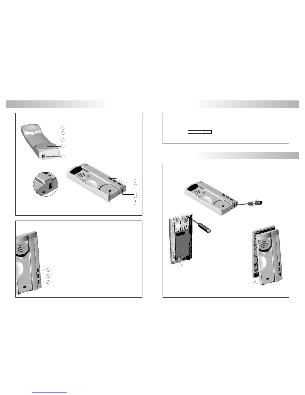
DOOR PANEL DESCRIPTION
oor panel description.
D
1xxx
2xxx
grille module
600
closing heads
3xxx
push buttons module
CE-6xx embedding boxes
Sound module
EL530
EL531
EL540
, on video systems with b/w camera.
, on video systems with color camera.
, on audio systems.
, on audio and video systems.
O EL500 or EL501,
c , (page 112).
perating modes
onfiguration with dip switch
, on systems with more than eight push buttons.
Push buttons
encoder
EL516SE
Microprocessed
circuit
EL500SE
Informative window
Informative window to indicate of a visual way that the system is busy. It is recommended
use the following types of installations:
- Buildings or backbones with more than one access.
- Systems with general door panels.
*
*
104103
Page 4

Modules
Model
W
H
D
106105
DOOR PANEL INSTALLATION
mbedding box positioning.
E
1650
1850
1450
reparing the cables entry.
P
Break the bottom flange to pass the cables through. In case of door panels
with more than one embedding box, break the side flanges and
attach the embedding boxes using UC junctions.
1
CE610
125
140
56
Compact
CE615
125
220
56
2
CE620
125
257
56
3
CE630
125 mm.
374 mm.
56 mm.
*
*
Compact size Stadio Plus (audio/video) panels, allow configurations up to 10 push buttons.
lace the embedding box.
P
ssembly the door panel modules.
A
DOOR PANEL INSTALLATION
The upper part of the door panel should be placed at 1,65m. height roughly. The hole dimensions
will depend on the number of door panel modules.
The door panel has been designed to be placed under most of the environmental conditions.
However it's recommended to take additional cautions like rainproof covers. To obtain a good
quality picture on video door entry systems, avoid direct incidence from light sources.
Pass the wiring through the hole made in the bottom part of the
embedding box. Level and flush the embedding box. Once
the embedding box is placed, remove the protective labels
from the attaching door panel holes.
Insert the header DOWN marked in the lower module and fix it by screwing the module shafts.
Place the module spacer between lower and next modules, assuring that the spacer adjustment
notches are inside the panel. Fix the module by screwing the shafts. Repeat this procedure in
case of door panels with one more module (the maximum number of modules placed vertically
is three).
Insert the header UP marked in the last module and fix it by screwing the supplied screws.
Page 5
108
107
DOOR PANEL INSTALLATION
DOOR PANEL INSTALLATION
1
2
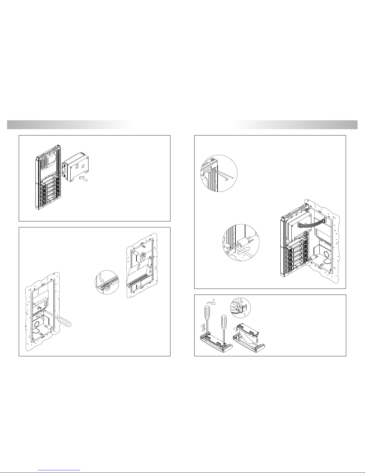
ssembly the sound module.
A
ssembling the EL500SE microprocessed circuit
and the EL516SE push buttons encoders.
A
old the door panel on the embedding box.
H
lace the label (informative window).
P
Before connecting the circuit of the informative
window (if it exists) for the indication of busy
system, should place the identification label.
insert a flat screwdriver to lever the flange to
access to the place of the label. Once put the
label replace the circuit.
Insert the sound module in the grille module. For
a proper assembly, align the light push button
and the microphone rubber of the sound
module with its corresponding holes in the
grille module.
The EL500SE circuit is to be assembled on the top of
the embedding box. Insert the circuit in the top
flanges of the embedding box (1). Push-in the
circuit in the bottom flanges (2) by pressing the pcb
board.
To assembly the EL516SE encoder, screw the top tab of the
case to the corresponding plastic lug of the embedding
box.
In case of more than one encoder, place them underneath or
in the next embedding box.
The use of EL516SE encoders is only necessary for panels
with more than 8 push buttons. Each encoder allows to
connect 15 push buttons, obtaining a maximum of 120
push buttons by using 8 encoders.
Select a direction to open the door panel; this selection should ease the
door panel wiring. The opening direction will be settled through the
hinges position, that must be passed through the header clips as
shown. For example, if the hinges are placed on both clips of the
lower header, the door panel will open downwards; if they are
placed on the right clips of both headers, the door panel will open to
left.
T o hold the door panel on the embedding box,
insert the hinges in the embedding box
lockers as shown.
Link the sound module with the EL500SE
microprocessed circuit by using the supplied
flat cable.
Page 6

110
109
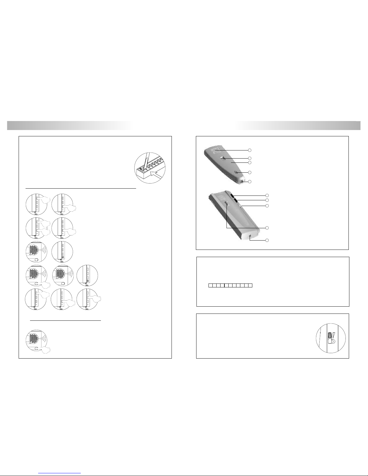
ush buttons wiring.
P
DOOR PANEL INSTALLATION DOOR PANEL INSTALLATION
lace the nameplate labels.
P
Open the label holder.
Place the label and
close.
Plug the push buttons connection cable to the CN6 connector
of the EL500SE microprocessor circuit, this cable has 10
conductors (P1 to P8, B and CP) for the connection of push
buttons or EL516SE.
The CP terminal must be connected to the push buttons
common terminal and to the CP terminal of the push
buttons encoder circuits. Connect B terminal to the B
terminal of the encoders.
Link the push button inputs (P1...P8) to the push buttons
and/or to the encoder circuits (P) as shown in the example.
EL-516SE
BCP P
CN1
CN6
EL516SE
Description CN2 conector
1
2
3
4
9
10
11
12
13
14
15
5
6
7
8
CN2 CN3
CP: Black
B: Red
P9: Green
P10: Orange
P11: Blue
P12: Violet
P13: Yellow
P14: White
P15: Brown
: Grey ( )
EL516SE
Description CN3 conector
**
P5
P6
P7
P8
P4
P3
B
o
hr noe r u
bt nTo t e e c d
rs opsh utos
CP
P2
IMPORTANTE: In case of more than one access, wire all the push buttons and modules EL-516SE
following the same order in all the door panels.
CP
P8
B
P7
P1P6P2
P5
P3
P4
Top vie w
CP: Black
B: Red
P1: Green
P2: Orange
P3: Blue
P4: Violet
P5: Yellow
P6: White
P7: Brown
P8: Grey
Colours codes
CP
P8
B
P7
P1P6P2
P5
P3
P4
Top vie w
CP: Black
B: Red
P1: Green
P2: Orange
P3: Blue
P4: Violet
P5: Yellow
P6: White
P7: Brown
P8: Grey
Colours codes
CP
B
P15
P9
P14
P10
P13
P11
P12
Topview
Colours codes
EL500SE
Description CN6 conector
( ) No function.
**
ush buttons wiring.
P
For a quality finish, pass the push buttons wires through the
spacer hole of the closest module. It's recommended to
2
use wires of less than 0,25mm section.
Twist the call wires as shown. The call wires will be
connected to the EL500SE microprocessed circuit or
to the corresponding EL516SE push buttons encoder.
IMPORTANT: link the push buttons common terminal of the
several push buttons modules. The common terminal of
the push buttons contained in a module are linked from
factory. The CP terminal of the EL500SE microprocessed
circuit must be connected at the push buttons common
and to the CP terminal of the corresponding EL516SE
encoder circuit (if it exists).
Page 7
112
111
ush buttons limit.
P
ush buttons digital code.
P
The maximum number of push buttons to be connected depends on the number of installed
EL516SE encoders, as it is shown on the following chart:
Without EL516SE circuit:
With 1 EL516SE circuit:
With 2 EL516SE circuits:
With 3 EL516SE circuits:
With 4 EL516SE circuits:
With 5 EL516SE circuits:
With 6 EL516SE circuits:
With 7 EL516SE circuits:
With 8 EL516SE circuits:
8
7 + 15 = 22
6 + 15 + 15 = 36
5 + 15 + 15 +15 = 50
4 + 15 + 15 + 15 +15 = 64
3 + 15 + 15 + 15 +15 + 15 = 78
2 + 15 + 15 + 15 +15 + 15 + 15 = 92
1 + 15 + 15 + 15 +15 + 15 + 15 + 15 = 106
0 + 15 + 15 + 15 +15 + 15 + 15 + 15 +15 = 120
1
P2
1
P1
31
P4
61
P6
91
P8
16
P3
46
P5
76
P7
106
2
2
32
62
92
17
47
77
107
3
3
33
63
93
18
48
78
108
4
4
34
64
94
19
49
79
109
5
5
35
65
95
20
50
80
110
6
6
36
66
96
21
51
81
111
7
7
37
67
97
22
52
82
112
8
8
EL516SE terminals
EL500SE terminals
38
68
98
23
53
83
113
9
9
39
69
99
24
54
84
114
10
10
40
70
100
25
55
85
115
11
11
41
71
101
26
56
86
116
12
12
42
72
102
27
57
87
117
13
13
43
73
103
28
58
88
118
14
14
44
74
104
29
59
89
119
15
15
45
75
105
30
60
90
120
DOOR PANEL INSTALLATION DOOR PANEL INSTALLATION
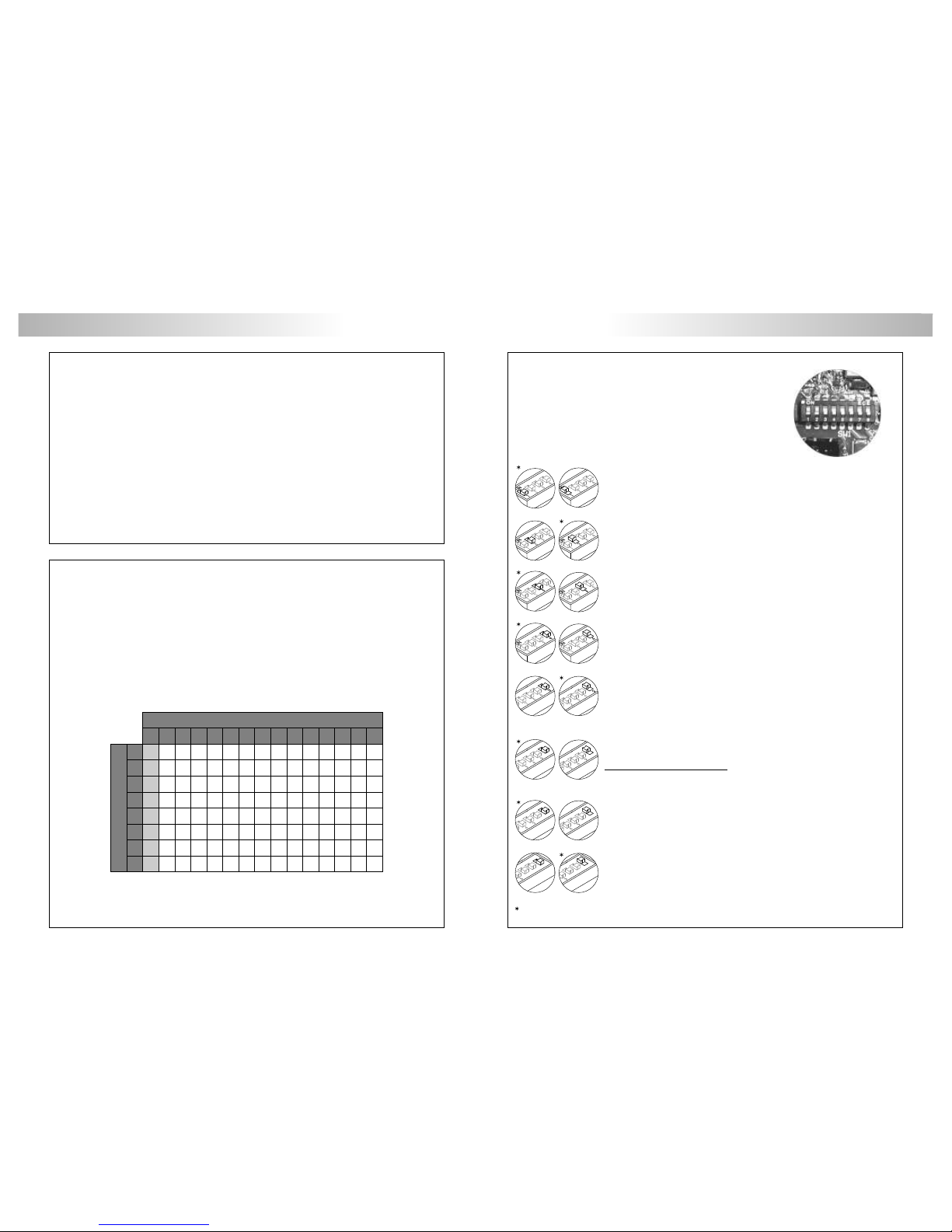
escription of the SW1 configuration dip-switch of
D
the EL500SE microprocessor module.
Placed to OFF if the EL500SE microprocessor module is configured as EL500
.
Set to ON if the EL500SE microprocessor module is configured as EL501
(general door panel).
operating mode
operating mode
Selects the d done from the ('AP'
terminal), see page 145.
Placed to ON: door opening timed at 3 seconds.
Set to OFF: door opening timed at 15 seconds.
oor opening time, external push button
Selects the type of cable to be used for the video signal.
Placed to OFF: coaxial cable RG-59 o RG-11.
Set to ON: twisted pair .
Selects if the door panel has telecamera or not. In case of door panels without
telecamera (EL540 sound module) set to ON.
Plus system, loads the installation with a communications resistor Plus. For a
proper system operation, placed to ON only in the closest door panel to the
backbone installation or in the general door panel (if exists), set the rest to
OFF.
Set to ON so that the volume tone emitted by the door panel:
(call reception, busy system and lock release) are HIGH, or placed to OFF if a
LOW volume tone is desired.
Uno System, loads the installation with a communications resistor Uno. For a
proper system operation, set to ON only in the closest door panel to the
backbone installation, placed the rest to OFF .
With digital repeater RD Plus/Uno:
In the backbone installation or after the inner door panel in systems with
general door panels, placed the door panel/s to OFF .
6
6
7
6
7
6
Placed to ON, the calls made on the door panel will be transferred to the
porter's exchange (if exists).Set to OFF , the call is received in the apartment.
In general door panels systems with porter's exchange, this function is only
applicable to the general door panels not to the inner door panel/s.
Factory default
6
7
8
6
7
8
The SW1 configuration dip-switch is located at the right side of
the circuit. It is accessed by opening the terminal connection
block protection cover.
In case to combine these door panels with coded door panels or porter's exchange it will be
necessary to know these codes for a properly system configuration.
The codes shown on the first column (shadowed) correspond with the push buttons directly
connected to the corresponding terminal on the CN6 terminal connector of the EL500SE
circuit, or with the terminal 1 of its corresponding EL516SE encoder.
Page 8

114
113
DOOR PANEL INSTALLATION GENERAL DOOR PANEL INSTALLATION
inary coding of the SW2 configuration dip switch
B
of the EL500SE microprocessor module.
The switches set to OFF have null value. The values of the switches
set to ON are shown in the enclosed chart.
The backbone code will be calculated as the sum result of the
switches values set to ON.
Example: 64+0+16+0+4+2+1=87
Switch number:
ON value:464532616788492101
escription of the SW2 configuration dip-switch of
D
the EL500SE microprocessor module.
The SW2 configuration dip-switch is located in the center
of the circuit. It is accessed by opening the terminal
connection block protection cover.
Allows to activate the autoswitch-on function (audio-video communication
without previous call) at the door panel that has this switch to ON position.
In systems with several door panels activate this function only in one of
them; in systems with general door panel this function can be activated in
one door panel of each inner backbone (building).
Set to ON for monitor or telephones programming. Once the programming
progress is finished return the switch to OFF position. The programming
process is described on pages 124 (monitors), 127 and 131 (telephones).
In general door panel (EL501 mode), set to ON for general door panel
push buttons programming or backbone (building) monitor/telephones.
The programming process is described on pages 114 to 116. Once the
programming progress is finished return the switch to OFF position.
Set to OFF in case of a master door panel. Each system must have only one
master door panel; the rest must be slaves (ON).
In systems with general door panel, set as master one door panel of each
inner backbone (building) and the general door panel as slave. Of this
way, the user will be able to distinguish since door panel are calling him.
Switches number 4 to 10 set the building code. In backbones with several
door panels, set the same code in all the panels; in systems with general
door panel, set different codes for each inner backbone (building). Set a
code between 1 and 120 for inner backbones (up to 127 with coded
panel) and a code 0 ( ) for general door panel/s. T o set the
code use binary coding as shown on the next paragraph.
Factory default
Factory default
Configure the of the general door panel in EL501 mode, (see page 112).microprocessor module
Locate the SW2 configuration dip switch of the general door
panel to program, placed in the center of the EL500SE circuit.
With the switches 1 and 3 to OFF , set the switch 2 to ON: to
show that the system is ready for programming, the general
door panel will reproduce a tone.
Pick up the monitor/telephone handset of
the apartment to program and press the
door release push button until to establish
communication of audio with the general
door panel.
Press the general door panel push button that will call to this
monitor or telephone. At this moment the general door
panel will reproduce a tone. To finish the push button
programmation, replace the monitor/telephone handset;
to show that the push button has been succesfully
programmed, the general door panel will reproduce a tone.
Make a call to check that the push button has been succesfully programmed.
Repeat these steps to program the rest of push buttons.
Once the programming has been finished, set to OFF the programming
switch. If you don't, the general door panel will reproduce a tone to advise
that the system is still into programming mode.
eneral door panel (programming modes).
G
This programming mode allows to assign a monitor / telephone (programmed) to the push button of
the general door panel that it wishes to call.
Before the monitors/telephones of the inner door panel/s must be programmed, see page 124
(monitors), 127 and 131 (telephones).
IMPORTANT: Before programming the general door panel push buttons, switch off the porter's
exchange (if exists).
Programming the push button (by call of monitor/telephone):
T-940Plus T-740Plus
The general door panel permits the following programming modes:
O Programming the push button (by call of monitor).
O Programming the push button (with a backbone code).
O Programming the push button (with a monitor/telephone code).
O Programming the monitor/telephone.
rogramming the push buttons of the general door panel.
P
Page 9

GENERAL DOOR PANEL INSTALLATION
Define a backbone code to program with dip switches Sw2-4 to Sw2-
10. Set a code between 1 and 120. To set the code use binary
coding, (see page 113).
Press the general door panel push button that is wished has this
backbone code. At this moment the general door panel will
reproduce a tone, confirming that the push button has been
succesfully programmed.
Repeat these steps to program the rest of push buttons. Once the programming has been finished,
set to OFF the programming switch. If you don't, the general door panel will reproduce a tone to
advise that the system is still into programming mode.
Programming the push button (with a monitor/telephone code):
This programming mode allows to assign a monitor/telephone code to push button of the general
door panel.
Locate the SW2 configuration dip switch of the general door
panel to program, placed in the center of the EL500SE circuit.
With the switches 1 and 3 to ON, set the switch 2 to ON: to
show that the system is ready for programming, the general
door panel will reproduce a tone.
Press the general door panel push button that is wished has this
monitor/telephone code. At this moment the general door
panel will reproduce a tone, confirming that the push button
has been succesfully programmed.
Repeat these steps to program the rest of push buttons. Once the programming has been finished,
set to OFF the programming switch. If you don't, the general door panel will reproduce a tone to
advise that the system is still into programming mode.
Define a monitor/telephone code to program with dip switches Sw2-4
to Sw2-10. Set a code between 1 and 120. To set the code use
binary coding, (see page 113).
nformative window connection.
I
DOOR PANEL INSTALLATION
The EL500SE microprocessor module supplies a cable with conector
for the indication of busy system.
Insert the side of the cable that takes the connector in the connector
CN3 of the EL500SE microprocessor module. It is accessed by
opening the terminal connection block protection cover.
Connect the red cable to the terminal 1 of the informative window
circuit and the white cable to the terminal 2 (if the informative
window exists).
This programming mode allows to assign to a monitor / telephone a push button of the general door
panel that it wishes to call.
Before the push button of the general door panel must be programmed with backbone and
monitor/telephone code, (see page 115).
Programación del monitor/teléfono:
Locate the SW2 configuration dip switch of the general door
panel to program, placed in the center of the EL500SE circuit.
With the switch 1 to OFF and 3 to ON, set the switch 2 to ON:
to show that the system is ready for programming, the general
door panel will reproduce a tone.
Then program the monitor/telephone, as it is described in the page 124 (monitor), 127 and 131
(telephone), (see manual T1ML if the monitor/telephone is Platea Uno or T-940 Uno).
Bear in mind the configuration dip switch (as it is described in the previous step).
rogramación de los monitores y teléfonos desde una Placa General.
P
GENERAL DOOR PANEL INSTALLATION
Programming the push button ( ):with a backbone code
This programming mode allows to assign a backbone code to push button of the general door panel.
Locate the SW2 configuration dip switch of the general door
panel to program, placed in the center of the EL500SE circuit.
With the switch 1 to ON and 3 to OFF, set the switch 2 to ON:
to show that the system is ready for programming, the general
door panel will reproduce a tone.
115
116
Page 10
118
117
amps wiring.
L
DOOR PANEL INSTALLATION
LOCK RELEASE INSTALLATION
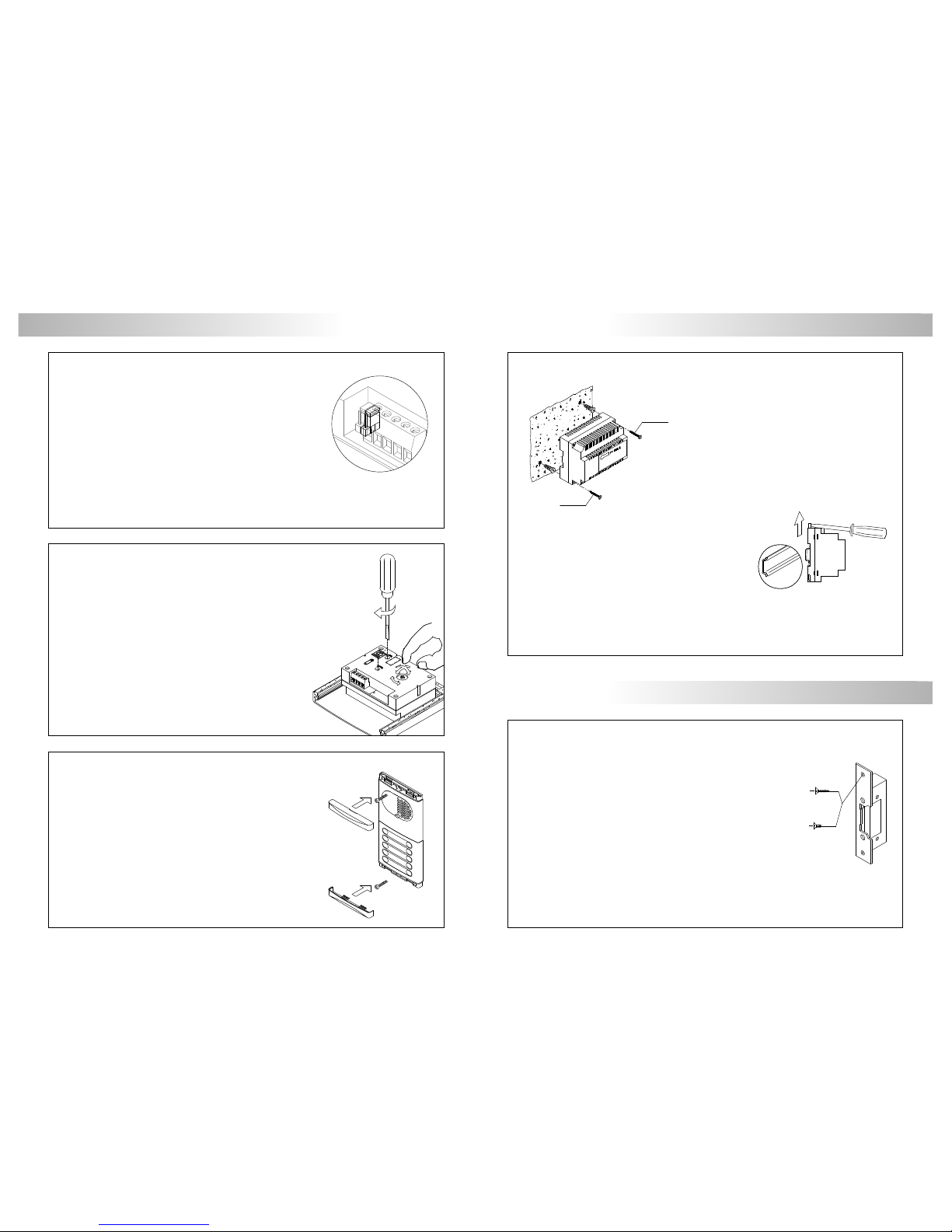
nstalling the FA-PLUS and FA-PLUS/C power supplies.
I
DIN 46277
f3,5 x 25
DIN-7971
f3,5 x 25
DIN-7971
M4x8
f3,5 x 25
DIN-7972
DIN-963
POWER SUPPLY INSTALLATION
ock release installation.
L
inal adjustments.
F
lose the door panel.
C
Fix the door panel by using the supplied
screws.
Finish the door panel assembly by pressing
the closing heads.
Once the nameplate labels are placed, wire the lamps from different
modules and connect them to terminals L1 and L2 of the sound
module.
If the number of door panel lamps is higher than eight, connect a TF-
104 transformer between ~1 and ~2 terminals of the sound
module and change JP2 jumper position.
NOTE: Don't change JP1 jumper position. JP1 and JP2 jumpers are placed on the left side of the
sound module terminal connector.
If the TF-104 transformer with alternating current lock release is also used, wire ~1/~2
terminals of the sound with CV1/CV2 terminals respectively of the EL500SE module.
Replace the protection cover once the input terminals have been wired.
If after starting the system it's considered that the audio
volume isn't correct, proceed with the necessary
adjustments as shown.
The telecamera has a pan and tilt mechanism built in to adjust
the telecamera position.
In case of low light conditions, an external illumination can be
activated by connecting a SAR-12/24 relay between
terminals '+H' and 'L2' of the sound module.
The power supply must be installed in a dry and
protected place. It's recommended to protect the
power supply by using a thermo-magnetic circuit
breaker. Use a ground connection with FA-Plus
power supply.
To install the power supply directly on the wall, drill two holes of
Ø6mm. and insert the wallplugs. Fix the transformer with the
specified screws.
The power supply can be installed on a DIN 46277
guide simply pressing it.
T o disassemble the power supply from the DIN guide,
use a plain screwdriver to lever the flange as shown
on the picture.
The FA-Plus/C model uses 6 units over DIN guide and
10 units the FA-Plus model.
IMPORTANT : the maximum number of units that can be connected to a F A-Plus/C power supply is
10, and 50 units in case of a FA-Plus model. Link power supplies to connect more
units than the specified as it's shown on page 132.
If the lock release will be installed in a metal door, use a
Ø3,5mm.
drill and tap the hole
. In case of wood door, use a Ø3mm. drill.
IMPORTANT : the lock release must be of 12Vd.c. or a.c.
See page 132 (a.c. lock releases) and page 133 - 144 (d.c lock releases)
Page 11

120
119
j
lk
m
a.
b.
c.
d.
e.
f .
g.
h.
i .
j .
k.
l .
m.
Handset.
B/W or color screen (depending on the model).
Front film.
Function push buttons.
Cord.
Attachment holes.
Identification label.
Connecting points.
CN4 connector.
Three positions call reception volume control.
Cable slot.
Contrast control (color control in case of color screen).
Brightness control.
MONITOR DESCRIPTION MONITOR DESCRIPTION
escription of the Platea Plus monitor.
D
unction push buttons.
F
escription of the identification label.
D
a
b
e
d
c
f
g
i
h
PLATEA-PLUS
REF
11758802
CODE
10060045
VERSION
5.00
Nº SERIE
100615137263
MASTERSLAVE
INTER A1
CODIGO / CODE
PUERTAESCALERA PISO
Floor DoorStair
ATENCIÓN
Alta tensión. No abrir la tapa.
Manipular sólo por personal
del servicio técnico.
WARNING
High voltage. Don't open cover.
Handle only by technical service.
PLATEA-PLUS
REF
11758802
CODE
10060045
VERSION
5.00
NºSERIE
100615137263
MASTERSLAVE
INTER A1
CODIGO/CODE
PUERTAESCALERA PISO
Floor DoorStair
ATENCIÓN
Altatensión.Noabrir la tapa.
Manipularsóloporpersonal
delserviciotécnico.
WARNING
Highvoltage.Don'topen cover.
Handleonlybytechnical service.
On-Off push button. After any monitor reset and during the next 45 seconds, all the
monitor functions will be disabled, with the exception of call reception.
If the handset is on the craddle allows the activation of an optional second camera (*). If
not, allows to make an intercom call or to activate the second camera (*).
If the handset is on the craddle allows the activation of an optional device. If not, allows to
call to a slave porter's exchange (*) or to activate the optional device.
If the handset is on the craddle allows to see the picture from the master door panel. If
not, allows to establish audio and video communication with the door panel that has
been configurated with the autoswitch-on function. This function is disabled if a
communication is already established.
If the handset is on the craddle sends a panic call to the porter's exchanges that have
enabled the reception of this type of call. If not, allows to call to the master porter's
exchange. During call reception and communication progresses allows the lock
release activation.
(*) Second camera activation and call to a slave porter's exchange functions require an internal
modification of the monitor. If any of these functions are required, contact with your nearest
authorized distributor.
Second camera activation disables the intercomm function and call function to a slave porter's
exchange disables optional device function.
For an easiest repair , replacement or increasement of
the existing monitors, fill the indentifying label
information.
MASTER: master monitor.
SLAVE: slave monitor.
INTER: slave monitor with intercom function.
A1: monitor connected to an auxiliary device.
CODE: push button code (see page 111).
STAIR: backbone code (building) (see page 113).
Page 12

122
121
V
in
V
out
Malla
Shield
Malla
Shield
A
HZ-
INT
SA
CTO
2C
A1
VP
MP
D
REF
RCPL-PLUS
LOTE
CODE
11758882
Colocar la parte superiorde la regleta a 1,60m. del suelo.
Place the top part of the monitor connector at 1,60m.from the floor.
50mm.
50mm.
Presionarpara abrir.
Press to open.
escription of the RCPL-Plus
D
monitor connector.
a
a
b
b
f
e
d
c
a. Wall attachment hole (x4).
b. Monitor attachment hook (x2).
c. Vertical wiring input.
d. Attachment clip.
e. Wiring input hole.
f. Installation terminals:
positive, ground.
video signal coaxial input.
coaxial shield.
video signal coaxial output.
audio communication.
digital communication.
door bell push button input.
intercom.
auxiliary calling device output.
video distributor activation output.
2nd camera activation output.
optional device activation output.
twisted pair video signal.
+, –:
Vin :
Malla:
Vout :
A :
D :
HZ- :
INT :
SA :
CTO :
2C :
A1 :
Vp, Mp :
L562 module for video installations
E
with twisted pair cable.
andling the end of line jumper.
H
hanging the front film.
C
MONITOR ADJUSTMENTS MONITOR CONNECTOR DESCRIPTION
Locate the CN4 connector , that's placed in the monitor base. Remove the
existing jumper and plug the EL562 module.
NOTE: on this type of installations the EL500SE microprocessed circuit
must be setting with SW1-3 to ON (page 112). Refer to the specific
installation diagram.
The end of line jumper is placed on the CN4 connector, that can be
located on the monitor base.
In case of twisted pair cable installations, the end of line jumper is
placed in the EL562 module, also located in the CN4 connector of the
monitor base.
Do not remove the jumper on monitors where the video cable finish.
Remove the jumper on monitors where the video cable continue.
The monitor is supplied with a reversible front film, that allow the owner
to choose between two colors.
To change the front film, remove the front plate by inserting a plain
screwdriver in the triangle marks, as it is shown on the drawing.
Terminals +, – and Malla (shield) are duplicated for easiest cascade installation of parallel
monitors or telephones. If the first monitor is not placed on the connector, cascade units will not
be powered.
Page 13
124
123
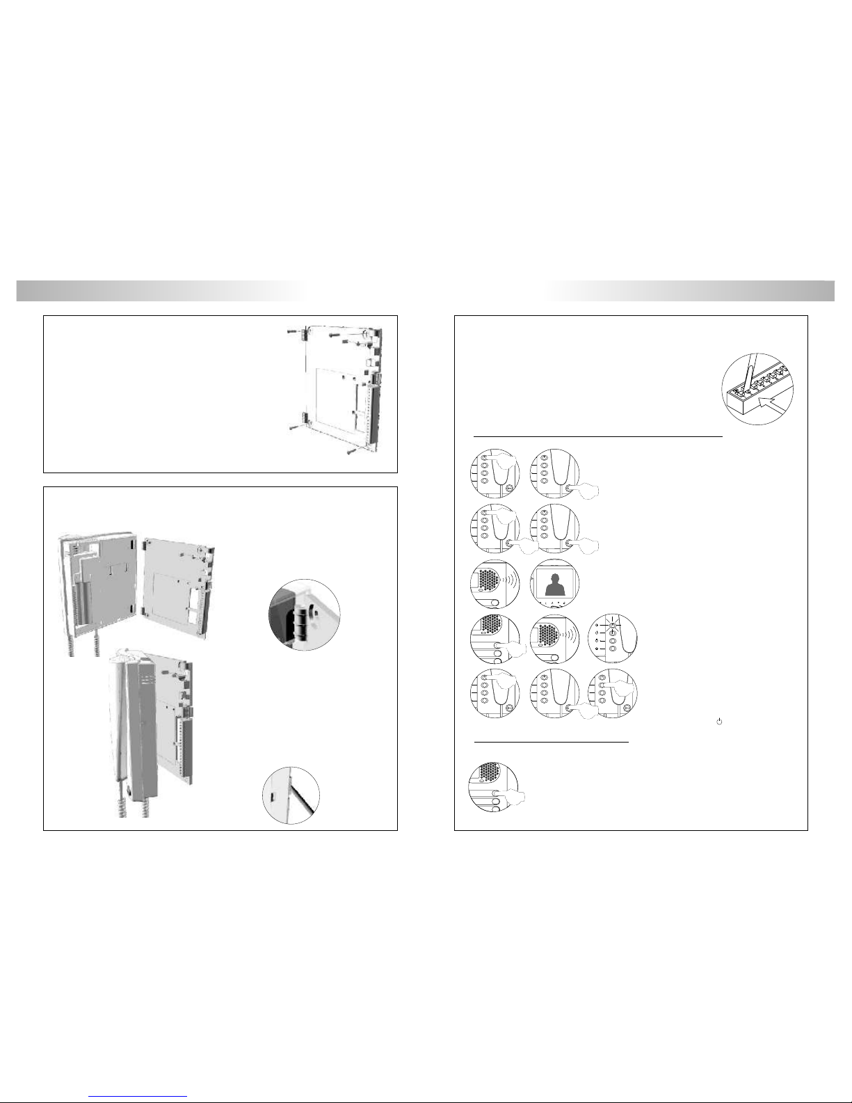
MONITOR INSTALLATION MONITORS PROGRAMMING
ix the monitor connector to the wall.
F
ix the monitor.
F
rogramming the Platea Plus monitors.
P
Set to ON the switch number 2 of the SW2 configuration dip switch, that's
accessible in the EL500SE module by opening the terminal connector
protection cover.
The door panel will reproduce a sound to advise that the system has
entered into programming mode.
In systems with more than one door panel, the programming process shall
be done on the master door panel only.
T o program the monitor from a general door panel (if it exists), see page 116.
Avoid to place the monitor near to heating sources, in dusty
locations or smoky environments.
T o install the monitor directly over the wall, drill two holes of
Ø6mm. and use the supplied screws.
The upper part of the monitor connector must be placed
at 1,60m. height roughly. The minimum distance
between the monitor connector and the closest object
must be 5cm.
Place the monitor at right angles to the
connector and align the attaching holes of the
monitor with the attachment hooks of the
connector, as it is shown on the drawing .
Lock out the monitor. Press the right side till the
attachment clip locks the monitor firmly.
To disassemble the monitor from the connector,
use a plain screwdriver to release the
attachment clip. Remove the monitor from the
connector, with special attention do not falls.
Switch off the monitor to be programmed.
Once the monitor is off, press the door release push button.
With the door release push button pressed switch on the
monitor.
T o show that the system is ready for programming, the door
panel will reproduce a tone and the picture will appears
on the monitor. At this moment, the door release push
button can be released. Lift the handset to establish audio
communication with the door panel.
Press the door panel push button that will
call to this monitor. At this moment the
door panel will reproduce a tone and the
monitor led will blink.
T o program the monitor as master, switch it
off and on again.
To program it as slave, press the door
release push button.
To program it as slave with intercom
function press the push button.
Each apartment must have one master unit only; in case of parallel units configure them as slaves,
both monitors or telephones.
Make a call to check that the monitor has been succesfully programmed.
Repeat these steps to program the rest of monitors.
Once the programming has been finished, set to OFF the programming
switch. If you don't, the door panel will reproduce a tone to advise that the
system is still into programming mode.
Page 14
126
125
TELEPHONE DESCRIPTION TELEPHONE DESCRIPTION
escription of the T-940 Plus telephone.
D
a.
b.
c.
d.
e.
f.
g.
h.
i.
Telephone handset.
Speaker grille.
Microphone hole.
Subjection hole.
Telephone cord connectors.
Function push buttons.
On-Off light indicator.
Call reception volume control.
Hook switch.
a
d
c
e
i
h
e
b
f
g
unction push buttons.
F
a.
b.
c.
a
b
c
erminal connector description.
T
positive, ground.
audio, digital communication.
intercom.
auxiliary calling device output.
door bell push button input.
+ , :
A , D :
INT :
SA :
HZ- :
–
AD
+
_
SAINT HZ-
TELEPHONE INSTALLATION
ix the telephone.
F
The telephone has a three positions switch placed on the bottom
part of the telephone (closest to the telephone cord connector)
that allows to control the call reception level volume.
On-Off push button.
After any telephone reset, and during the next 45 seconds, all the
telephone functions will be disabled, with the exception of call
reception.
This push button allows to make an intercom call when the handset
is not on the craddle. This function is described on page 147.
If the handset is on the craddle sends a panic call to the porter's
exchanges that have enabled the reception of this type of call. If
not, allows to call to the master porter's exchange. During call
reception and communication progresses allows the lock release
activation.
It will be necessary to open the telephone for wiring and
fixing purposes. To open the telephone insert a plain
screwdriver into the slots and rotate it as shown.
Avoid to place the telephone near to
heating sources, in dusty locations or
smoky environments.
The telephone can be fixed using an
electrical embedding box or directly on
the wall, as shown on the picture. If the
telephone will be installed directly over
the wall, drill two holes of Ø6mm. on the
specified positions, using 6mm.
wallplugs and Ø3,5 x 25mm. screws.
Pass the installation wires through the corresponding hole and
connect them as shown on the installation diagrams.
Close the telephone as shown on the picture. Once the telephone
is closed, connect the handset using the telephone cord and put
it on the craddle.
Page 15
127
TELEPHONES PROGRAMMING
rogramming the T-940 Plus telephones.
P
Switch off the telephone to be programmed.
Once the telephone is off, press the door release push button.
Set to ON the switch number 2 of the SW2 configuration dip switch, that's
accessible in the EL500SE module by opening the terminal connector
protection cover.
The door panel will reproduce a sound to advise that the system has
entered into programming mode.
In systems with more than one door panel, the programming process shall
be done on the master door panel only.
T o program the telephone from a general door panel (if it exists), see page 116.
erminal connector description.
T
+, - :
A ,
D :
Al :
HZ :
SA :
INT :
PA :
Al+SA
_
AD Int PA
_
HZ +
128
TELEPHONE DESCRIPTION
.
D
escription of the T-740 Plus telephone
a
d
c
e
b
g
e
a.
b.
c.
d.
e.
f.
g.
h.
i.
Telephone handset
Speaker grille
Microphone hole
hole
Telephone cord connectors
release push button
Hook switch
Auxiliary function push button
Volume control
.
.
.
Subjection .
.
Door .
.
.
.
f
h
i
all volume control.
C
MAX
OFF
The telephone allows to regulate the call volume with a maximum,
medium and off value. With the help of the switch of three positions
placed in the right front of the telephone.
To show that the system is ready for programming, the door
panel will reproduce a tone and the telephone led will blink.
At this moment, the door release push button can be
released. Lift the handset to establish audio communication
with the door panel.
With the door release push button pressed switch on the
telephone.
Press the door panel push button that will call
to this telephone. At this moment the door
panel will reproduce a tone and the
telephone led will blink.
T o program the telephone as master , switch it
off and on again.
T o program it as slave, press the door release
push button.
T o program it as slave with intercom function
press the center push button.
Each apartment must have one master unit only; in case of parallel units configure them as
slaves, both monitors or telephones.
Make a call to check that the telephone has been succesfully programmed.
Repeat these steps to program the rest of telephones.
Once the programming has been finished, set to OFF the programming
switch. If you don't, the door panel will reproduce a tone to advise that the
system is still into programming mode.
Positive, ground.
SAV-90
Audio, digital communication.
Connection to external door release push button.
Door bell push button input.
Auxiliary calling device output
Intercom.
(18Vdc/0,5A max.)
.
Output for aux. relay activation
Page 16

.
F
unction push buttons
129
TELEPHONE DESCRIPTION
ix the telephone to the wallF.
It is necessary to open the telephone for wiring and fixing
purposes To open the telephone, insert a plain screwdriver
into the slots and gently lever as shown in the drawing
.
.
P
. C
.
.
ass the installation wires through the corresponding hole and connect
them as shown on the installation diagrams lose the telephone as
shown on the picture Once the telephone is closed, connect the
handset using the telephone cord and put it on the cradle
Avoid placing the telephone near sources of heat, in dusty
locations or smoky environments The telephone can be
fixed using an electrical embedding box or directly on the
wall, as shown on the picture If the telephone will be
installed directly over the wall, drill two holes of Ø6mm on
the specified positions, using 6mm wall plugs and Ø3.5 x
25mm screws
.
.
.
130
TELEPHONE INSTALLATION
If the handset is on the craddle sends a panic call to the porter's
exchanges that have enabled the reception of this type of call. If not,
allows to call to the master porter's exchange. During call reception
and communication progresses allows the lock release activation.
Auxiliary function push button, depending on setting in the SW1 dip
switch will realize one of the following functions: Autoswitch-on, "PA"
output, call to a slave porter's exchange and intercommunication.
escripción del microinterruptor de configuración.
D
escription of programming push button.
D
Factory default
"Autoswitch-on" mode: switches 1 and 2 to ON.
With the handset off the cradle, allows to stablish audio communication with the
door panel that has been configured with the autoswitch-on function. This
function is disabled if a communication is already established.
"PA" output mode: switches 1to ON and 2 to OFF:
Regardless of the handset's position, it activates the "PA" telephone output.
"Call to a slave porter's exchange" mode: switches 1 to OFF and 2 to ON.
With the handset off the cradle, allows to call to a porter's exchange that it is
configurated as slave.
" " mode: switches 1 and 2 to OFF .
With the handset off the cradle, allows to make an intercom call between two units
of the same apartment.
Intercommunication
P3
SW1
12
12
12
12
P3
The P3 programm push button is located in the top part left of the circuit,it is
accessed by opening the telephone. Allows to telephone enter in programming
mode with the door panel, (see programming process on page 131).
IMPORTANTE: Select before programming the telephone.the auxiliary function push button mode
The SW1 configuration dip switch is located in the top part left of the circuit,it is
accessed by opening the telephone and allow the next operation modes for the
auxiliary function push button:
Page 17

132
INSTALLATION DIAGRAMS
onnexion of an a.c. lock release.
C
ink of several power supplies units.
L
1st FA-Plus 2nd FA-Plus/C or FA-Plus
SEC
PRI
~~
Main
++
--
SEC
PRI
~~
Main
++
--
rogramación de los teléfonos T-740 Plus.
P
P3
T o show that the system is ready for programming,
the door panel and the telephone's handset will
reproduce a tone (the telephone led will light).
Audio communication can be established.
Press the door panel push button that will call to
this telephone. At this moment both door
panel and handset will reproduce tones (the
telephone led will slow blink).
P3
ON
T o programm the telephone as Master, press the
h (the telephone led will off).
Close the telephone.
ook switch
P3
ON
P3
ON
Set to ON the switch number 2 of the SW2 configuration dip switch, that's
accessible in the EL500SE module by opening the terminal connector protection
cover. The door panel will reproduce a sound to advise that the system has
entered into programming mode. In systems with more than one door panel,
the programming process shall be done on the master door panel only.
Each apartment must have one master unit only; in case of parallel units configure them as slaves,
both monitors or telephones.
Make a call to check that the telephone has been succesfully programmed. Repeat
these steps to program the rest of telephones.
Once the programming has been finished, set to OFF the programming switch. If
you don't, the door panel will reproduce a tone to advise that the system is still
into programming mode.
To programm the telephone as Slave, press the
P1 door release push button (the telephone
led will quick blink) and later press the hook
switch (the led will off).
Close the telephone.
P3
ON
P3
SW1
Open the telephone to programming (see page
130). Select in the SW1 dip switch the fuction
mode for the auxiliary
(see page 129) and later press the P3
programming push-button.
function push button
P1P2CN1
To programm the telephone as Slave +
Intercom., press the P2 auxiliary function
push button (the led will quick blink) and later
press the hook switch (the led will off).
Close the telephone.
P
S
SI
P1P2CN1
P3
SW1
P1P2CN1
ON
P3
ON
P3
SW1
P1P2CN1
ON
P3
SW1
P1P2CN1
ON
T o program the telephone from a general door panel (if it exists), see page 116.
131
TELEPHONES PROGRAMMING
If an alternating current lock release has been installed, use a TF-104 transformer or an EL 502
dc/ac converter
and connect it to the lock release as it is shown on the respective diagram.
Main
Va.c
Lock release
CN2
+AP--+CV1CV2-+12
SEC
PRI
230110 0
--
++
CN1
+
-
CV+
CV-
CN2 CN3
EL502 EL500SE
FA-PLUS/C
rev.938072
EL502 dc/ac converter and a.c Lock release
CN2
CV1CV2-+12
Main
*
EL500SE
TF-104
SEC
PRI
~~~~
TF-104 and a.c Lock release
IMPORTANT:If the TF-104 transformer is used
to supply the a.c lock release and the door
panel lamps, wire ~1/~2 terminals of the
sound module with CV1/CV2 terminals
respectively of the EL-500SE module.
*
Va.c
Lock release
If the quantity of monitors or telephones to be connected is bigger than the supported from one
power supply (see page 118), use additional power supplies to match the required quantity. The
first power supply should be connected to the door panel and to the first group of monitors or
telephones; connect the next groups to the positive terminal of its corresponding power supply.
T o wire several power supplies link their ground terminals.
NEVER link positive terminals of different power supplies.
To the door panel & to the first
group of monitors/telephones.
To the second group of
monitors/telephones.
Page 18

134
133
Main Main
Place this power supply
as closest as possible
to the first distributor.
ONE OR SEVERAL ACCESSES DOORS
ideo installation with coaxial cable.
v
1,00mm² 2,50mm²
0,25mm² 0,25mm²
RG-59 RG-59
Terminal
SECTIONS CHART
50m.
Distance
150m.
A , A , A, D
in out
V , V , V , V
in+ out+ in out
+, –, CV1, CV2
Take off JP1 jumper
of all the distributors
except in the last one.
FA-Plus/C o FA-Plus
SEC
PRI
~~
++
--
A
A
_
_
+
+
D
D
Malla
Malla
V
in
V
in
V
out
V
out
CN4
CN4
A
_
+
D
Malla
V
in
V
out
CN4
A
_
+
D
Malla
V
in
V
out
CN4
EED1
D1
D2
D2
+
+
D4L-PLUS
D4L-PLUS
JP1
JP1
S
S
oaxial cable characteristics RG-59 B/U MIL C-17.
C
SW1
SW1
D
Malla
Vin-AinAout Vin+ Vout-Vout+
CN2
+AP--+CV1CV2-+12
-
D
Malla
Vin-AinAout Vin+ Vout-Vout+
CN2
+AP--+CV1CV2-+12
-
FA-Plus/C
rev.938072
SEC
PRI
230110 0
--
++
SW2
SW2
Core max. electrical resistence to 20ºC
Copper core
Copper shield
ELECTRICAL CHARACTERISTICS
Nominal capacitance
Characteristic impedance
VALUES
75 3 W
+
-
<67pf/m
*
<158 W/Km
<10 W/Km
_
_
_
S
M
Velocity of Propogation
_
>66,6 %
INSTALLATION DIAGRAMS
Access door panel Access door panel
**
M =Master.
S =Slave.
The installation diagram shows the connection of a video system with one or several door panels
for the same building.
If the system has one access door panel only, override the wiring to the second door panel.
If the system has more than one access door panel, wire the second panel as shown on the
diagram. In case of more than two door panels, wire them as the second is connected.
Page 19

136
135
Main Main
* Take off JP1 jumper
of all the distributors
except in the last one.
1,00mm² 2,50mm²
0,25mm² 0,25mm²
CAT-5 CAT-5
Terminal
SECTIONS CHART
50m.
Distance
150m.
A , A , A, D
in out
V , V , V , M
in+,- out+,- p,d p,d
+, –, CV1, CV2
ideo installation without coaxial cable.
v
FA-Plus/C o FA-Plus
SEC
PRI
~~
++
--
JP1
AAD
D
CT
+
+
V
pi
V
d1
M
pi
M
d1
_
_
A
D
CT
+
V
d6
M
d6
_
AD+
V
po
M
po
_
D6L-Plus/2H
V
p
M
p
AD
_
+
EL562
JP1
VpM
p
AD
_
+
EL562
JP1
JP1
AAD
D
CT
+
+
V
pi
V
d1
M
pi
M
d1
_
_
A
D
CT
+
V
d6
M
d6
_
AD+
V
po
M
po
_
D6L-Plus/2H
V
p
M
p
AD
_
+
EL562
JP1
VpM
p
AD
_
+
EL562
JP1
FA-Plus/C
rev.938072
SEC
PRI
230
SW1 SW1
110 0
D
Malla
Vin-AinAout Vin+ Vout-Vout+
CN2
+AP--+CV1CV2-+12
-
D
Malla
Vin-AinAout Vin+ Vout-Vout+
CN2
+AP--+CV1CV2-+12
-
--
++
SW2 SW2
ONE OR SEVERAL ACCESSES DOORSINSTALLATION DIAGRAMS
* Place this power supply
as closest as possible
to the first distributor.
S
M
Access door panel Access door panel
The installation diagram shows the connection of a video system with one or several door panels for
the same building.
If the system has one access door panel only, override the wiring to the second door panel.
If the system has more than one access door panel, wire the second panel as shown on the diagram.
In case of more than two door panels, wire them as the second is connected.
IMPORTANT: For this type of installation, the door panels must have configured t
he switch nº.3 of
the SW1 configuration dip-switch to ON
in each (page112) and the monitors must
have an EL562 plugged in each (page 121).
M =Master.
S =Slave.
Page 20

138
137
Main Main
udio installation.
A
1,00mm² 2,50mm²
0,25mm² 0,25mm²
Terminal
SECTIONS CHART
50m.
Distance
150m.
A , A , A, D
in out
+, –, CV1, CV2
*Place this power supply
as closest as possible
to the first telephone.
FA-Plus/C o FA-Plus
A
A
+
+
_
_
D
D
T-740 Plus
T-740 Plus
A
+
_
D
T-940 Plus
A
+
_
D
T-940 Plus
FA-Plus/C
rev.938072
SEC
PRI
230
--
SW2 SW2SW1 SW1
110 0
++
D
Malla
Vin-AinAout Vin+ Vout-Vout+
CN2
+AP--+CV1CV2-+12
-
D
Malla
Vin-AinAout Vin+ Vout-Vout+
CN2
+AP--+CV1CV2-+12
-
SEC
PRI
~~
++
--
ONE OR SEVERAL ACCESSES DOORSINSTALLATION DIAGRAMS
S
M
Access door panel Access door panel
The installation diagram shows the connection of an audio system with one or several door panels
for the same building.
If the system has one access door panel only, override the wiring to the second door panel.
If the system has more than one access door panel, wire the second panel as shown on the diagram.
In case of more than two door panels, wire them as the second is connected.
M =Master.
S =Slave.
Page 21
SW1
D
Malla
Vin-AinAout Vin+ Vout-Vout+
CN2
+AP--+CV1CV2-+12
-
SW2
To monitors
Continues
in the following page
ES +
S1
SEC
PRI
~~
++
--
SW2
D4L-PLUS
JP1
FA-Plus o FA-Plus/C
Main
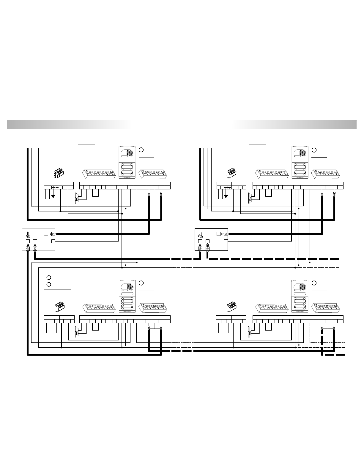
EL501 mode
To monitors
ES +
S1
FA-Plus o FA-Plus/C
SEC
PRI
~~
++
--
D4L-PLUS
JP1
Main
Inner door panel
D
Malla
Vin-AinAout Vin+ Vout-Vout+
CN2
+AP--+CV1CV2-+12
-
SW1
D
Malla
Vin-AinAout Vin+ Vout-Vout+
CN2
+AP--+CV1CV2-+12
-
D
Malla
Vin-AinAout Vin+ Vout-Vout+
CN2
+AP--+CV1CV2-+12
-
FA-Plus/C
rev.938072
SEC
PRI
230
Main
--
110 0
++
FA-Plus/C
rev.938072
SEC
PRI
230
Main
--
110 0
++
General door panel
SW2 SW1 SW2 SW1
EL501 mode
EL500 mode
General door panel
SS
M
EL500 mode
M
BACKBONE 1 BACKBONE 2 Inner door panel
140
139
GENERAL DOOR PANELINSTALLATION DIAGRAMS
M =Master.
S =Slave.
BACKBONE 0 BACKBONE 0
Page 22

142
141
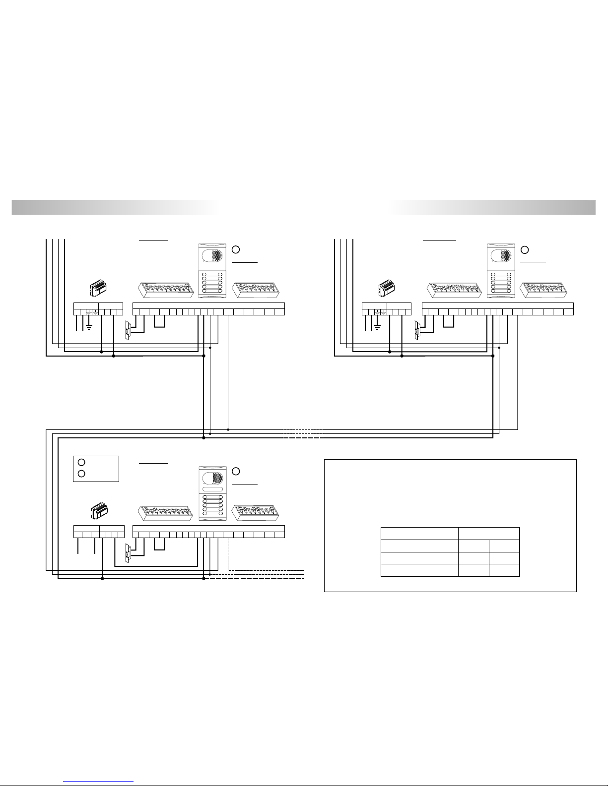
GENERAL DOOR PANELINSTALLATION DIAGRAMS
ideo installation with general door panel
to large residential complexes.
v
For greater distances contact our technical support department.
1,50mm² 2,50mm²
0,25mm² 0,25mm²
CAT-5
RG-59
Terminal
SECTIONS CHART
100m.
Distance
300m.
A , A , A, D
in out
V, V
in+ out+
V , V , V , V
in+ in- out+ out-
+, –, CV1, CV2
RG-59
CAT-5
Coaxial
Sw1-3 Off
Twisted pair
ES
+
S1
S2
Coming
from previous page
D4L-PLUS
JP1
ideo installation with general door panel
to large residential complexes.
v
Malla
Vin- Vin+ Vout-Vout+
Malla
Vin- Vin+ Vout-Vout+
SW1
D
Malla
Vin-AinAout Vin+ Vout-Vout+
CN2
+AP--+CV1CV2-+12
-
SW2
SEC
PRI
~~
++
--
SW2
FA-Plus o FA-Plus/C
FA-Plus o FA-Plus/C
SEC
PRI
~~
++
--
D
Malla
Vin-AinAout Vin+ Vout-Vout+
CN2
+AP--+CV1CV2-+12
-
SW1
Sw1-3 On
IMPORTANT NO TES:
T o install and configure properly, d
The installation diagram shows the connection of a video system with two general door panels and up to
120 inner door panels (backbones/buildings).
In case of more than two door panels, wire them as the second is conected.
In video systems use a D4L-Plus distributor before each inner building except in the last one. T ake off JP1
jumper of all the distributors except in the last one.
In video systems with use the D6L-Plus/2H distributor instead of D4L-Plus distributor . T ake off
JP1 jumper of all the distributors except in the last one. Add a negative in the inner building
installation riser, (see page 135).
Below shows the connection of the
coaxial cable.
o always follow the enclosed information.
twisted pair
twisted
pairinsteadof
*
Coaxial cable characteristics RG-59 B/U MIL C-17, (see page 134).
**
To monitors
Main
To monitors
Main
Inner door panel
EL500 mode
M
EL500 mode
M
BACKBONE 119 BACKBONE 120 Inner door panel
Page 23
To telephones To telephones
udio installation with general door panel
to large residential complexes.
A
1,50mm² 2,50mm²
0,25mm² 0,25mm²
Terminal
SECTIONS CHART
100m.
Distance
300m.
A , A , A, D
in out
For greater distances contact our technical support department.
+, –, CV1, CV2
SEC
PRI
~~
++
--
SW2
FA-Plus o FA-Plus/C
Main
D
Malla
Vin-AinAout Vin+ Vout-Vout+
CN2
+AP--+CV1CV2-+12
-
SW1SW1
D
Malla
Vin-AinAout Vin+ Vout-Vout+
CN2
+AP--+CV1CV2-+12
-
SW2
FA-Plus o FA-Plus/C
SEC
PRI
~~
++
--
Main
D
Malla
Vin-AinAout Vin+ Vout-Vout+
CN2
+AP--+CV1CV2-+12
-
FA-Plus/C
rev.938072
SEC
PRI
230
Main
--
110 0
++
General door panel
SW2 SW1
IMPORTANT NO TES:
T o install and configure properly, d
The installation diagram shows the connection of an audio system with one general door panel
and up to 120 inner door panels (backbones/buildings).
In case of more than one general door panel, wire them as it shows in the video installation
diagram, (see page 139).
o always follow the enclosed information.
Inner door panelBACKBONE 1 BACKBONE 120 Inner door panel
EL501 mode
EL500 mode
S
M
EL500 mode
M
BACKBONE 0
144
143
GENERAL DOOR PANELINSTALLATION DIAGRAMS
M =Master.
S =Slave.
Page 24

146
145
OPTIONAL CONNECTIONS OPTIONAL CONNECTIONS
xternal lock release activation.
E
uxiliary devices activation.
A
The use of a TF-104 transformer will be necessary to activate a second lock release.
onnecting the Platea Plus monitor
C
to a video recorder or TV.
A
_
+
D
Malla
V
in
V
out
CN4
Platea Plus
220 Vac/
1.8A max.
SAR-12/24
P
N
IN IN
NC NA C
()
*
The neutral supply from the stairs light will be wired through the relay contacts SAR-12/24, the maximum current for stairs
light will be 1.8A.
()
*
To distributor/
door panel.
To stairs light
push button
~~ ~~
Lock release
Vac.
TF-104
Main
PRI
SEC
SAR-12/24
IN IN
NC NA C
AP
_
Door panel
A1
A
_
+
D
Malla
V
in
V
out
CN4
Platea Plus
To distributor/
door panel.
A1
The lock release can be activated at any moment by using an external push
button, that must be connected between 'AP' and ' ' terminals of the door
panel.
Door opening timed at 3 or 15 seconds, with the help of the dip switch
SW1-2 (see page 112).
This function will allows to exit from the building being not necessary the use
of a key.
–
ctivation of a second camera.
A
A
_
+
D
Malla
V
in
V
out
CN4
SAR-12/24
IN IN
NC NA C
Platea Plus
2C
2 Camera
nd
The use of a SAR-12/24 relay will be required to activate a second camera and an internal
modification on the monitor shall be done, as it's described on page 120. This facility disables the
intercom function. If both functions are required, use A1 terminal to activate the second camera.
To activate this function, press monitor push button at any moment with no dependence of the
handset position.
If this device is shared for all the Platea Plus monitors, link their 2C terminal and use just one relay
unit. In case that each monitor has its own camera use a SAR-12/24 relay unit for each monitor
and don't link the 2C monitor terminals.
This push button can be used to activate other auxiliary devices, as the A1 terminal is used.
Usual applications are the surveillance of the elevator entrance, reception hall, ...
A
_
+
D
Malla
V
in
V
out
CN4
Platea Plus
If your TV or video recorder have a SCART connector , it will
be possible to view the picture from the door panel on
the TV screen.
Remove the end of line jumper, that's placed on the CN4
connector. Connect the coaxial cable between terminals
17 (shield) and 20 (hot) of the SCART connector .
T o activate auxiliary devices the use of a SAR-12/24 relay unit will be required. If this device is shared
for all the Platea Plus monitors, link their A1 terminal and use just one relay unit. In case that each
monitor has its own application use a SAR-12/24 relay unit for each monitor and don't link the A1
monitor terminals.
To activate this function, press monitor push button at any moment with no dependence of the
handset position.
Usual applications are the activation of stairs light, second lock release, ...
Page 25

ntercom function.
I
148
147
OPTIONAL CONNECTIONS OPTIONAL CONNECTIONS
oor bell push button connection.
D
xternal lock release activation with T-740Plus telephone.
E
A
+
_
D
T-740 Plus
SAR-12/24
P
N
220 Vac/
1.8A max.
IN IN
NC NA C
()
*
The neutral supply from the stairs light will be wired through the relay contacts SAR-12/24, the maximum current for stairs
light will be 1.8A.
()
*
uxiliary devices activation with T-740 Plus telephone.
A
To activate auxiliary devices the use of a SAR-12/24 relay unit will be required. If this device is
shared for all the T-740 Plus telephones, link their PA terminal and use just one relay unit. In
case that each telephone has its own application use a SAR-12/24 relay unit for each
telephone and don't link the PA telephone terminals.
T o activate this function, press telephone push button at any moment with no dependence of
the handset position.
Usual applications are the activation of stairs light, second lock release, ...
First t T-740 Plus telephone must be configured with SW1 dip switch in "PA" output mode
function
(see page 129).
he
Al
_
T-740 Plus
HZ-
-
HZ
-
T-940 Plus
Platea Plus
During call reception and communication progresses allows the
lock release activation, by using an external push button, that
must be connected between 'AI' and ' ' terminals of the
telephone.
–
T-740 Plus
A
+
_
D INT
A
_
+
D INT
Malla
V
in
V
out
CN4
Platea Plus
T-940 Plus
T-740 Plus
PA
IMPORTANTE: The T-740 Plus telephone must be configured with SW1 dip switch in "Intercom"
mode function
(see page 129).
*
Platea Plus monitor and (*) T-740Plus and T -940 Plus telephones have intercom facility between two
units of the same apartment
. T o enable this function check the following conditions:
- One of the units has been configurated as master and the other unit as slave with intercom, as
described on pages 124, 127 and 131. In case to intercom one monitor with one telephone,
configure the monitor as master.
- Link the INT terminal of the units, as it is shown on the enclosed diagram.
To establish an intercom communication lift the handset and press the intercom push button;
acoustic tones will be reproduced on the handset confirming the call is in progress or that the
other unit is communicating with the door panel. To establish communication lift the handset of
the called unit
. If during an intercom communication a call is made from the door panel, acoustic
tones will be heard on the master unit handset and the picture will appear in case of a monitor;
press the intercom push button of the master unit to establish communication with the door panel,
or press the door release push button to activate the lock release.
The reproduced acoustic tones are different depending on their provenance, that allows the user to
distinguish where the call is made from.
To distributor/
door panel.
To stairs light
push button
The Platea Plus monitor and the T-740 Plus and T -940 Plus telephones can be used to receive the
calls made from the apartment door, saving the use of a bell. Wire the push button of the
apartment door to the 'HZ ' and ' ' monitor or telephone terminals.
The reproduced acoustic tones are different depending on their provenance, that allows the user
to distinguish where the call is made from. If during a conversation a call is made from the
apartment door, acoustic tones will be reproduced on the handset to advise that someone is
calling.
––
Page 26

150
149
NOTAS/NOTES
An easy way to check that the system is working properly is to disconnect the wiring from the door panel
and to check the monitor directly connected to the EL500SE circuit.
No shortcircuit will damage the connected units, with the exception of a shortcircuit between CTO and ' '
monitor or distributor terminals.
O Nothing operates.
w Check the output power supply voltage between ' ' and '+' terminals: it should have 17,5 to
18,5Vd.c. If not, disconnect the power supply from the installation and measure again. If it's
correct now, it means there is a short circuit in the installation: disconnect the power supply
from mains and check the installation.
w Check that 'D' terminal is not shortcircuited with ' ' or '+' terminals.
w Check that 'D' terminal hasn't been changed by 'A' terminal somewhere in the installation.
O Inappropriate audio level.
w Adjust the level volumes as shown on page 117. In case of feedback, reduce the audio levels until
feedback fade out. If feedback don't dissapears refer to the following hint.
O Continuous audio feedback.
w Check that 'A' terminal is not shortcircuited with other terminals.
O Door open function no operates.
w Remember that this function is only available during call and communication progresses.
w
w
O The system cannot be programmed.
w Check that the switch number 2 of the SW2 configuration dip switch is set to ON (see page 113)
and that the programming steps are correctly followed.
w Check that 'D' terminal is not shortcircuited with other terminals.
O Some units don't receive calls.
w Remember that each apartment must have a master unit only. Check that the units are switched on
and correctly programmed.
–
–
–
The CV1 and CV2 terminals for door opening are voltage free outputs. The cable requires a
connection depending on whether 12Vdc (page 133 to 144) or 12Vac (page 132) is needed.
Make a short circuit between the 'CV1' and 'CV2' terminals on the EL500SE microprocessor
circuit; there should be12V (d.c. or a.c. depending on the type door release installed) between
the terminals on the door release.If so, check the lock release and its wiring.
TROUBLESHOOTING HINTS
 Loading...