


Assembly manual
Audio and Video
door entry system
(Mechanical assembly
of the door panel)
Tnexa Modular ML rev.0112
Cód. 50121535
Nexa
Modular

21
INTRODUCTION
INDEX
First of all we would like to thank and congratulate you for the purchase of this product manufactured by
Golmar.
The commitment to reach the satisfaction of our customers is stated through the ISO-9001 certification
and for the manufacturing of products like this one.
Its advanced technology and exacting quality control will do that customers and users enjoy with the
legion of features this system offers. To obtain the maximum profit of these features and a properly wired
installation, we kindly recommend you to expend a few minutes of your time to read this manual.
22
Introduction ...........................................21
Index.....................................................21
Important.............................................21
Door panel description .......................21-22
Door panel installation ................................
Embedding box positioning ...................23
Embedding box installation ..............23-24
Assembly the electronic modules ............24
Hold the frame .....................................25
Connection and configuration ...........25
Close the frame....................................25
Door panel assembly ............................26
Double door panel assembly..................27
Close the door panel.............................28
IMPORTANT
OSee user manual corresponding for details of connection, configuration and
programming system (it is supplied with the sound module).
OUser manual reference:
w4+N system, user manual T655.
wVista system, user manual T631/R5.
wPlus system, user manual T631/Plus.
DOOR PANEL DESCRIPTION
oor panel description.
D
General detail of parts, for assembly the door panel.
Aluminium door panel
Electronic
modules
Frame modulesEmbedding boxes
Continue

22
DOOR PANEL DESCRIPTION
Sound module
EL655
EL631/R5
EL631/Plus
Push buttons electronic module
EL610A
EL610D
Short connection cable
It is supplied with EL610A module "length: 8 cm" (4+N installation).
It is supplied with EL610D module "length: 16 cm" (Vista and Plus installation).
, for 5 single or 10 double push buttons (4+N installation).
, for 5 single or 10 double push buttons (Vista and Plus installation).
, sound module (4+N installation).
, sound module with color camera (Vista installation).
, sound module with color camera (Plus installation).
Connection cable
RAP-610A "code: 11895610, length: 55 cm" (4+N installation).
RAP-610D "code: 11895710, length: 27 cm" (Vista and Plus installation).
Door panel description.
Grille module:
N1000/AL
N1110/AL 1P.
N2220/AL 2P.
Closing heads: 60xx
Push buttons module: 3xxx
Nexa spacer module
Screws of fixation of header (x4)
Lateral rod (x2)
Lateral rod Door panel UNE rod
*
*
Door panel UNE rod: It allows to join 2 door panels, (see page 27).
Screws of fixation of embedding box (x2)
Coming from previous page

23
DOOR PANEL INSTALLATION
24
1650
1850
1450
mbedding box positioning.
E
The upper part of the door panel should be placed at 1,65m. height roughly. The hole dimensions
will depend on the type of door panel.
The door panel has been designed to be placed under most of the environmental conditions.
However it's recommended to take additional cautions like covered places. To obtain a good
quality picture on video door entry systems, avoid direct incidence from light sources.
reparing the cables entry.
P
Break the bottom flange to pass the cables through. In case of door panels
with more than one embedding box, break the side flanges and
attach the embedding boxes using UC junctions.
1
NCEV90CS
99
135,5
40
Modules
Model
An
Al
P
2
NCEV90C
99
238
56
3
CEV90
99 mm.
328 mm.
56 mm.

24
DOOR PANEL INSTALLATION
ssembly the electronic modules.
A
Insert the sound module in the top part of the module frame.
Align the tabs on the sound module in their respective housings of the module frame and
then exercise a light pressure until correct placement.
Frame
If there is push buttons module repeat the above process, locating under the sound module,
as shown in the drawing.
Frame
lace the embedding box.
P
Pass the wiring through the hole made in the bottom part of the
embedding box. Level and flush the embedding box. Once
the embedding box is placed, remove the protective labels
from the attaching door panel holes.
Sound module:
EL655 (4+N).
EL631/R5 (Vista).
EL631/Plus (Plus).
Push buttons electronic
module:
EL610A (4+N).
EL610D (Vista and Plus).

DOOR PANEL INSTALLATION
old the frame on the embedding box.
H
Insert the hinge that it is supplied with the product in the embedding
box, as shown in the drawing.
To hold the frame on the embedding box, insert the hinge in the
housings arranged for this purpose in the frame, as shown in
the drawing.
The frame can now be folded horizontally facilitating the connection
and adjustments in the sound module and push buttons electronic
module.
onnection and configuration.
C
For connection push buttons, nameplate labels, configuration, adjustments and
programming, see the manual supplied with the sound module.
lose the frame.
C
25
26
Once finished the works of wiring, configuration and final
adjustments, fix the frame in the embedding box with the
supplied screws.
DOOR PANEL INSTALLATION
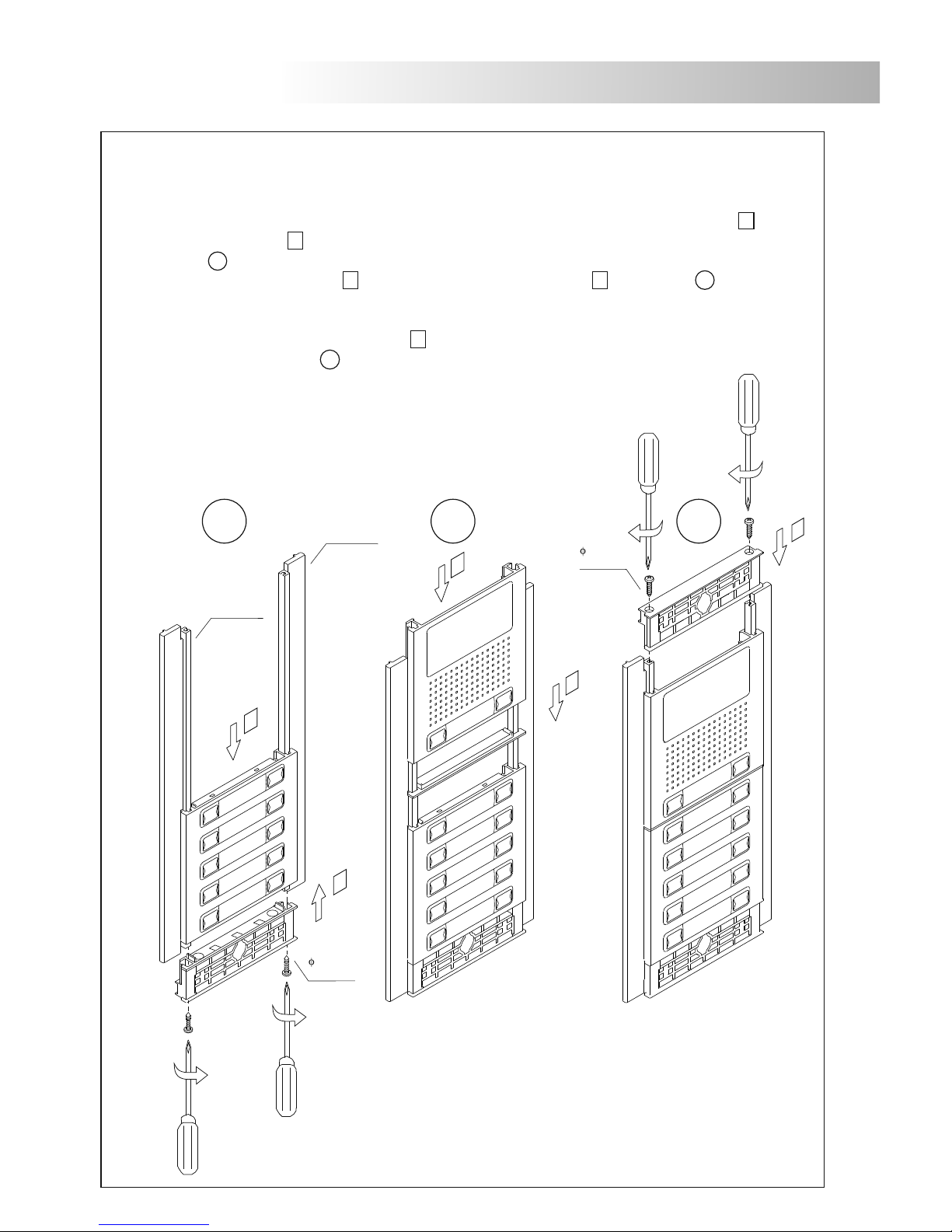
oor panel assembly.
D
Insert a header in the lateral rods (at the bottom part) and fix it with the supplied screws (step 1 ), then
insert the module (step 2 ). If the door panel is more than one module insert first the lower module,
see picture A .
Place the spacer module (step 3 ) and insert the next module (step 4 ) see picture B . Repeat this
procedure in case of door panels with one more module (the maximum number of modules placed
vertically is three).
To finish insert the second header (step 5 ) in the lateral rods (at the top part) and fix it with the
supplied screws, see picture C .
2,9 x 13
DIN-7981
A B C
1
2
3
4
5
2,9 x 13
DIN-7981
Lateral Rod
Lateral Rod
26
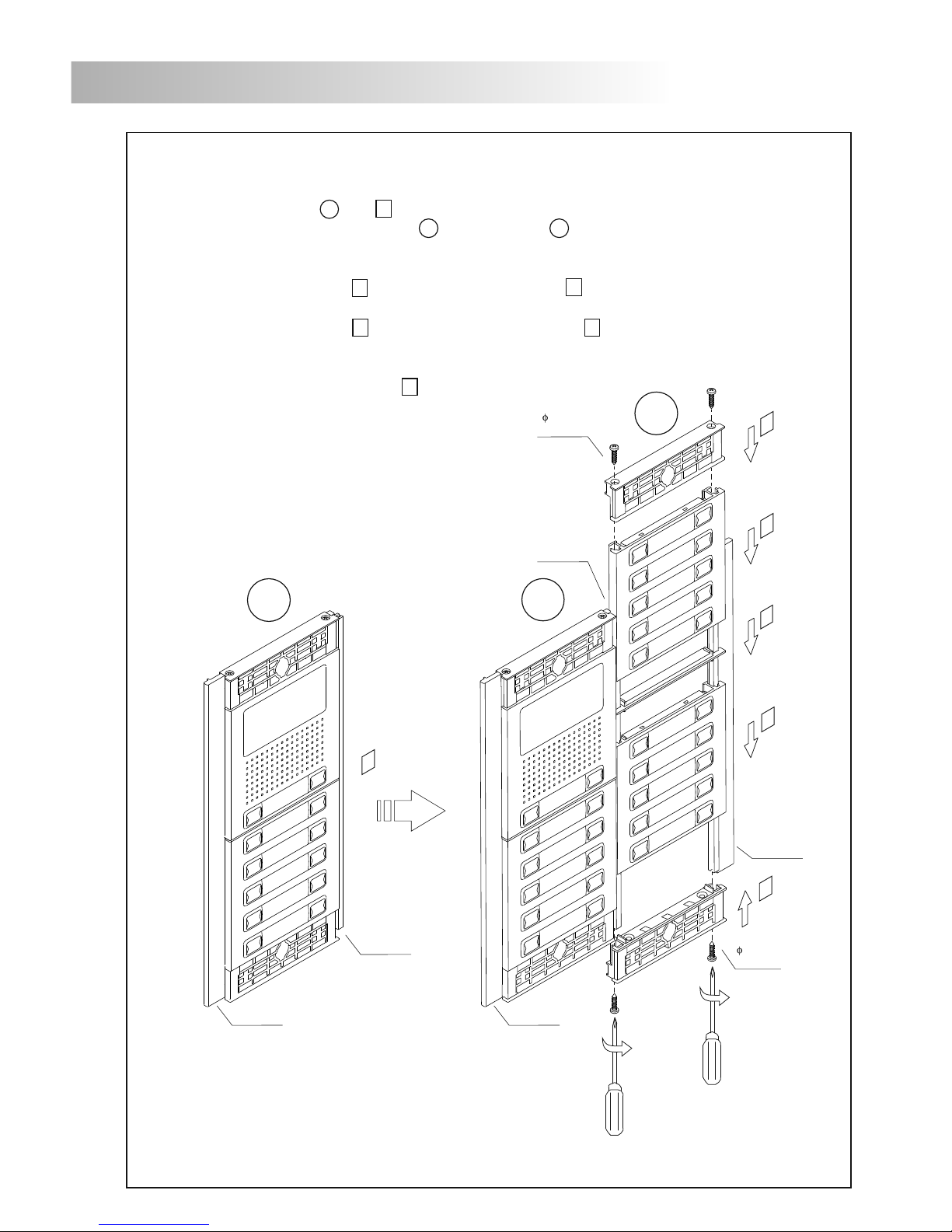
ouble door panel assembly.
D
Assembly the door panel A (step 1 ), as it is described in page 26 "Door panel assembly". Bear in mind
that the rod that will join the door panel A and door panel B have to be of the type door panel UNE
rod, see picture below.
Insert a header between door panel UNE rod and the second lateral rod (at the bottom part) and fix it
with the supplied screws (step 2 ) then insert the module (step 3 ). If the door panel is more than one
module insert first the lower module.
Place the spacer module (step 4 ) and insert the next module (step 5 ). Repeat this procedure in case of
doo r panel s with one more module (the maximum numbe r o f module s placed verticall y i s three).
To finish insert the last header between door panel UNE rod and the second lateral rod (at the top part)
and fix it with the supplied screws (step 6 ).
2,9 x 13
DIN-7981
Lateral Rod
A
Door panel
UNE Rod
A
B
5
1
2
4
3
6
Door panel
UNE Rod
2,9 x 13
DIN-7981
IMPORTANT: Once finished the adjustments, stick the adhesive gasket (that it is supplied with the set
of closing heads N60XX CMPL) in the .door panel UNE rod
Lateral Rod
Lateral Rod
DOOR PANEL INSTALLATION
27
28

fix the door panel in the embedding box with the supplied screws.
lose the door panel.
C
Door panel: Double door panel:
Finish the door panel assembly by placing the closing heads, put the head on one side and then
make a slight pressure on the other end, to its correct placement.
DOOR PANEL INSTALLATION
28

29
30

30
NOTAS/NOTESNOTAS/NOTES

Golmar se reserva el derecho a cualquier modificación sin previo aviso.
Golmar se réserve le droit de toute modification sans préavis.
Golmar reserves the right to make any modifications without prior notice.
golmar@golmar.es
www.golmar.es
31
 Loading...