

Page 1
4
MOUNTING CONFIGURATIONS
*
( )
*
( )
For more information, see the TCODE/CA NEXA user manual (code 50123681)
https://doc.golmar.es/search/manual/50123681
NEXA audio and video
door entry system
Code 50123681 TN3301 REV.0 162
Golmar reserves the right to make any modifications without prior notice.
QUICK GUIDE
www.AlphaCommunications.com 1-800-666-4800
Sistemasde comunicación S.A.
Access control module
NEXA AUDIO AND VIDEO DOOR ENTRY SYSTEM - ACCESS CONTROL MODULE
N3301
access control module
SECSEC
~~ ~~
PRIPRI
~~ ~~
MainMain
12VAC
transformer
12VAC
transformer
(1)
(1)
C2NC1 NC2
CN1
P
~ ~
C1NA1
NA2
PL1
PL2
-
PL2
PL1
Va.c
Va.c
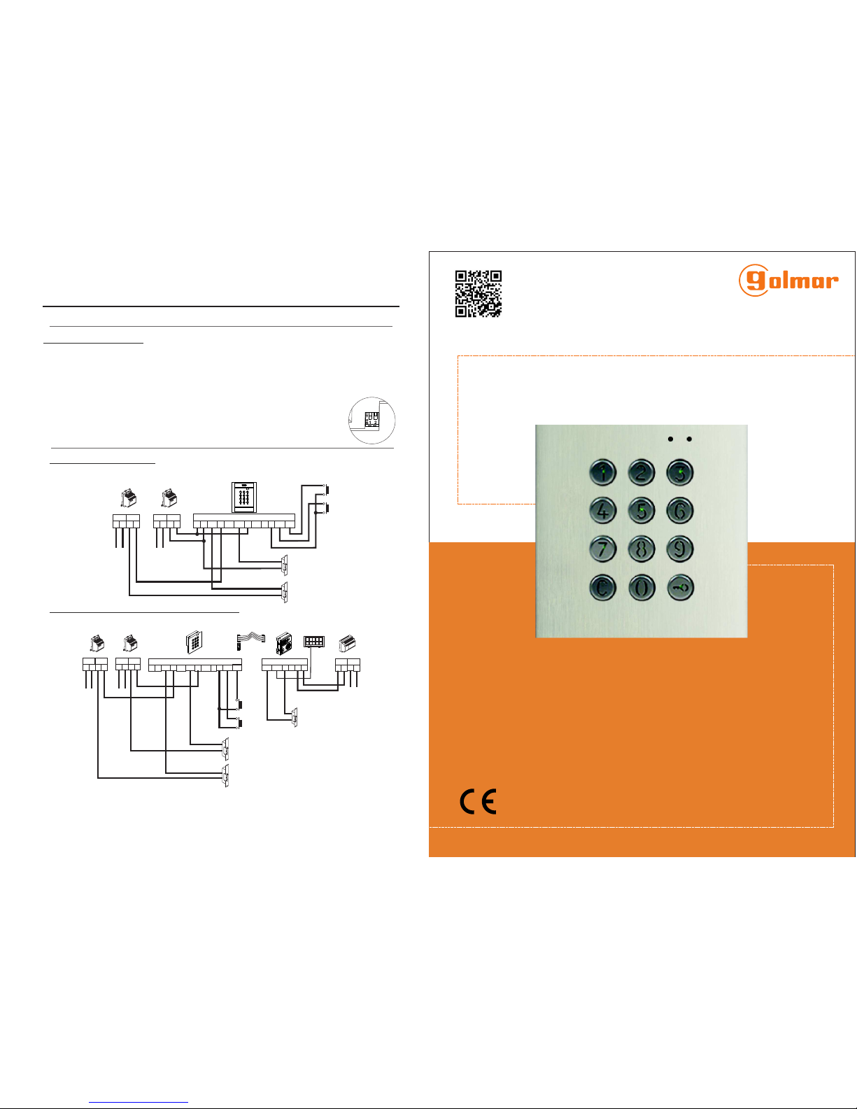
WIRING DIAGRAMS
*
( )
Use the varistor supplied with the N3301 module when using an AC lock release directly
on the terminals of the lock release.
(1)
The coded panel with display is configured by adding a display to the previous configuration,
thereby enabling the actions performed with the door panel to be viewed. This enables calls to be
made using the monitor code or the contacts residents list. It is also possible to gain access to the
building using the numeric code and view, on the door panel screen, the status of the actions
performed.
Coded panel with display:
In this operating mode, the SW1 DIP switch has no function.
N3301
access control module
FA-Plus or FA-Plus/C
power supply unit
C2NC1 NC2
CN1
P
~ ~
SEC
+
-
PRI
~~
Red
C1NA1
NA2
PL1
PL2
-
Door panel with EL632/PLUS -
EL642/PLUS sound module
CN1
+
- -
+
CV1CV2
10
1
9
2
8
3
7
4
6
5
CN3
CN8
PL2
PL1
SEC
~~
PRI
~~
Main
SEC
~~
PRI
~~
Main
12VAC
transformer
12VAC
transformer
(1)
Va.c
(1)
Va.c
CN3
Standalone access control:
Access control combined with Nexa door panels:
50122310
Page 2
2
*
( )
For more information, see the TCODE/CA NEXA user manual (code 50123681)
https://doc.golmar.es/search/manual/50123681
3
MOUNTING CONFIGURATIONS
*
( )
*
( )
For more information, see the TCODE/CA NEXA user manual (code 50123681)
https://doc.golmar.es/search/manual/50123681
SAFETY PRECAUTIONS
-Always disconnectthepowersupply before installing or making modifications tothe devices.
-The fitting and handling ofthese devices mustbe carried out by .authorizedpersonnel
- The wiringmust runat least .40 cmaway fromany other wiring
- Onthe powersupply unit:
wDo notovertighten thescrews on theconnector.
wInstallthe power supplyunit ina dryand protectedplace free from the riskof waterleaks or sprays.
wAvoid locations thatare humid,dusty or nearheat sources.
wEnsure thatthe airvents are freefrom obstructionso that aircan circulatefreely.
wToavoid damage,the power supplyunit mustbe firmly securedin place.
wTo preventelectricshock, do not removethe cover or handle the wiringconnectedto theterminals.
- Codedmodule andaccess control.
- Canbe combinedwith “Nexa Modular”and “InoxModular” door panels.
- Configurationprogrammable usinga numeric keypad,PC ortablet.
- Residentslist withup to 1,990contacts dependingon setup.
-Status LEDsand tones.
CHARACTERISTICS
*
( )
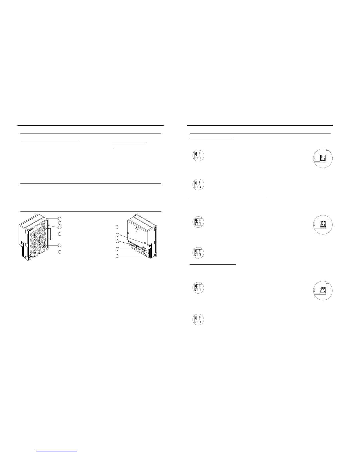
MODULE DESCRIPTION
*
( )
a
b
c
d
e
f
g
h
i
j
k
a. Front
b.
Green LED
c. Red LED
d. Numeric keypad
e. Key button
f. Cancel button
g. Back
h. SW1 DIP switch
i. JP1 tamper jumper
j. Connection block
k. Nexa Bus connectors
: Power input (Do not use when connecting the Nexa Bus link hose)
: Normally open output relay 1.
Common relay 1.
: Normally closed output relay 1.
: Normally open output relay 2.
: Common relay 2.
: Normally closed output relay 2.
: Panic output.
: Negative.
: Input for exterior button relay 1.
: Input for exterior button relay 2.
~ ~
NA1
C1
NC1
NA2
C2
NC2
P
PL1
PL2
Standalone access control:
The standalone access control enables access to the building by entering a numeric code using
the N3301 module.
Access control combined with Nexa door panels:
Configuring access control with call buttons enables users to make calls to apartments using
the call buttons and to gain access to the building by entering a numeric code into the N3301
module.
Coded panel without display:
The coded door panel enables calls to be made to apartments by entering the monitor code
and access to be gained to the building by entering a numeric code into the N3301 module.
Use toreset thespecial installer PINto thefactory code.
Proceed asfollows: Set DIP switch1 to ON. The modulewill emit 2 beeps
and thegreen LED onthe front willlight up for1 second. Thenset the DIP
switch to OFF (the code is now the one assigned at the factory). If the
access control module was locked duringthis process, the special unlock
PIN willalso bereset to thefactory code.
Set DIP switch 2 to OFF to configure the door panel as a standalone module.
Use toreset thespecial installer PINto thefactory code.
Proceed asfollows: Set DIP switch1 to ON. The modulewill emit 2 beeps
and thegreen LED onthe front willlight up for1 second. Thenset the DIP
switch to OFF (the code is now the one assigned at the factory). If the
access control module was locked duringthis process, the special unlock
PIN willalso bereset to thefactory code.
Set DIP switch 2 to OFF to configure the door panel as a standalone module.
Use toreset thespecial installer PINto thefactory code.
Proceed asfollows: Set DIP switch1 to ON. The modulewill emit 2 beeps
and thegreen LED onthe front willlight up for1 second. Thenset the DIP
switch to OFF (the code is now the one assigned at the factory). If the
access control module was locked duringthis process, the special unlock
PIN willalso bereset to thefactory code.
Set DIP switch 2 to ON to configure the door panel as a coded door panel.
NEXA AUDIO AND VIDEO DOOR ENTRY SYSTEM - ACCESS CONTROL MODULE
NEXA AUDIO AND VIDEO DOOR ENTRY SYSTEM - ACCESS CONTROL MODULE
 Loading...