

Page 1
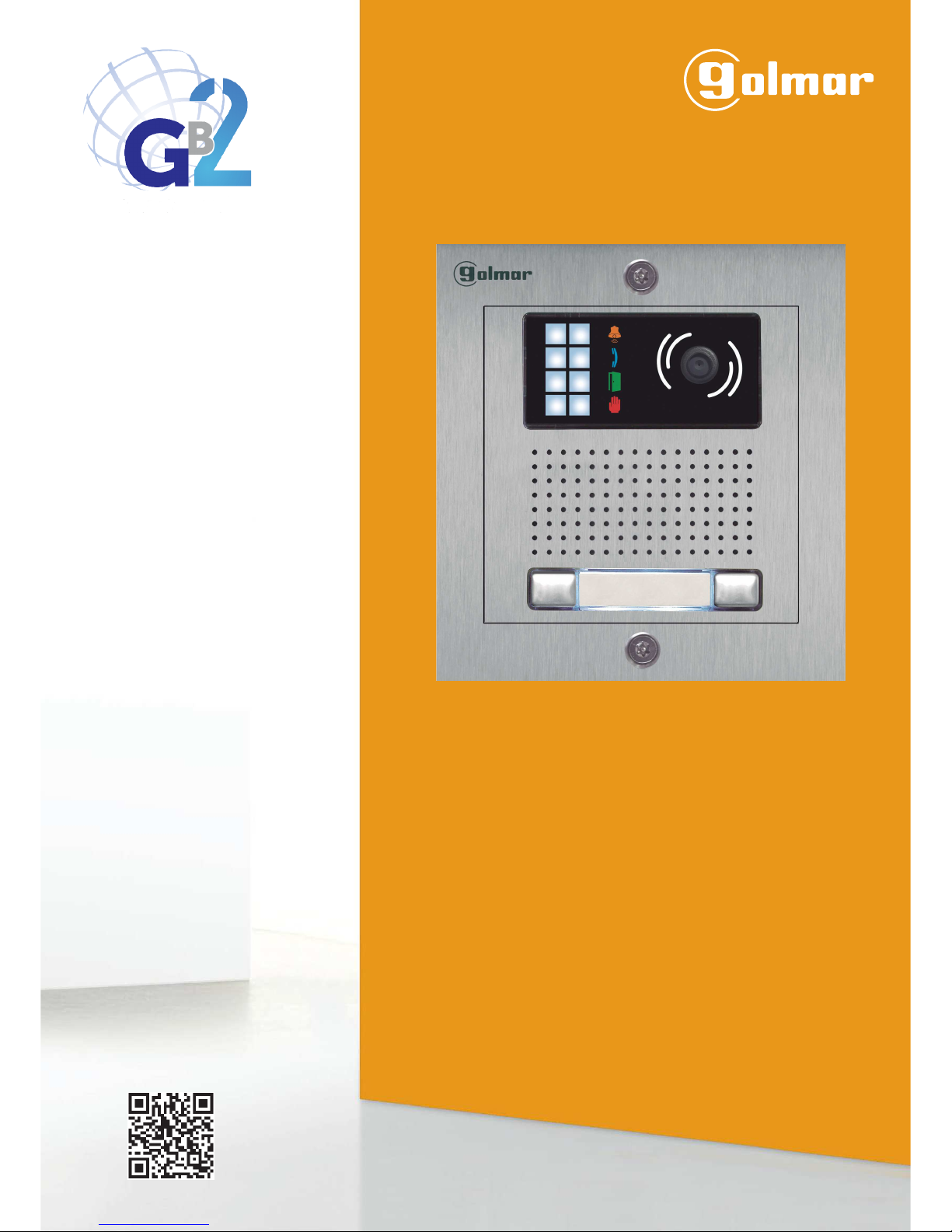
USER MANUAL
Code 5012 12 71 T ENKIT632A PENTHA REV.0 12 7
G 2B Video Door Entry
System Kit
2-wire installation
Stainless Steel
Nexa Modular
TECHNOLOGY
Page 2

INTRODUCTION
First of all, we thank and congratulate you for purchasing this product.
Our commitment to achieving the satisfaction of customers like you is manifested through our ISO-9001 certification
and the manufacture of products like the one you have just purchased.
Its advanced technology and strict quality control will ensure that customers and users enjoy the numerous features
that this device offers. To get the most out of them and ensure proper operation from day one, we recommend that you
read this instruction manual.
CONTENTS
2
SET-UP WARNINGS
- Do not overtighten the screws on the power supply connector.
- Always disconnect the power supply before installing or making modifications to the devices.
- The fitting and handling of these devices must be carried out by .authorised personnel
- The wiring must run at least .40cm away from any other wiring
- Before connecting the device to the mains, check the connections between the door panel, power supply unit,
distributors, camera interface, GSM interface, monitors and telephones.
- Use the Golmar cable (2x1mm ).RAP-2150
2
- Always follow the instructions contained in this manual.
Introduction................................................................................................................................................................... 2...
Contents..........................................................................................................................................................................2
Set-up warnings............................................................................................................................... . 2.............................. .
Safety precautions........................................................................................................................................... ..3..............
Characteristics.............................................................................................................................................................. . 3. .
System operation.......................................................................................................................................... 3...................
Description of the EL632 GB2Asoundmodule.................................................................................................................4.
Stainless Steel Nexa Modular Door Panel.........................................................................................................................
................................................................................................................................. 5.....
Positioning the embedding box
............................................................................................................................ 5...................Preparing the cable entry
........................................................................................................ 6.........................Codes assigned to the call buttons
...................................................................................................... . .6. .................................Description of the DIP switch
..................................................................................................................... 7.....Description of the configuration jumper
............................................................................. 7..................Description of the illumination LEDs (low light conditions)
.................................................................................................... 7......Description of the visual signals on the door panel
............................................................................7.Description ofthevocalsynthesis(audiblesignalsonthedoorpanel)
.............................................................................................................. 8.Setting the door panel communication volume
..................................................................................................................... .8... .Selecting the vocal synthesis language
............................................................................................................................ 8.Adjusting the vocal synthesis volume
.............................................................................. .9. .Configuring the contact type for Relay 1 and Relay 2 (lock release)
....................................................................................... .9................................. .Inserting the button identification labels
...................................................................................................................................................9Closing the door panel
FA-GB2/Apower supplyinstallation
......................................................................................................................... ..10.... .
Installation of the lock release....................................................................................................................................... 10..
Wiring diagrams........................................................................................................................................ 11-18................
Notes........................................................................................................................................................................... .19.
STAINLESS STEEL NEXA MODULAR GB2 VIDEO DOOR ENTRY SYSTEM KIT – HOUSES
Page 3
CHARACTERISTICS
- Video door entrysystem with simplified wiring (non-polarised 2-wire bus).
- Up to 4 access panels (DP-GB2Adistributor required for more than one access panel) per installation.
- Up to 2 apartments (NX5110 Pentha 1-apartment kit and NX5220 Pentha 2-apartment kit) per installation.
- Maximum 18 Pentha monitors per installation.
- Maximum 16 Pentha monitors in one apartment.
- Maximum 4 Pentha monitors in parallel (without distributors) per installation.
- Call confirmation tone.
-Visual signals on the door panel for people with impaired hearing (indicating call process, communication, door open
and channel busy).
- Audible signals on the door panel for people with impaired vision (indicating call in progress, missed call, door open, call
finished and engaged).
- Door opening timeable at 1 or 5 seconds.
- 2 outputs for independently activated lock releases.
- Relay 1 output to activate the DC orAC lock releases actuated by relay.
- Relay 2 output to activate the DC orAC lock releases actuated by relay.
- Input for exterior door opening button (Relay 1 output).
- Input for exterior door opening button (Relay 2 output).
- Maximum distance between the power supply and the furthest door panel: 80m with a cross-section of 1mm .
2
- Maximum distance between the power supply and the last distributor: 80m with a cross-section of 1mm .
2
- Maximum distance between distributor and monitor: 40m with a cross-section of 1mm .
2
SYSTEM OPERATION
3
SAFETY PRECAUTIONS
- Always disconnect the power supply before installingor making modifications to the devices.
- The fitting and handling of these devices must be carried out by .authorised personnel
- The wiring must run at least 40 cm away from any other wiring.
- On the power supply unit:
wDo not overtighten the screws on the connector.
wInstall the power supply unit in a dry protected location free from the risk of dripping or splashing water.
wAvoid locations thatare humid, dusty or near heat sources.
wEnsure that the air vents are free from obstruction so that air can circulate freely.
wTo avoid damage, the power supply unit mustbe firmly secured in place.
wTo prevent electric shock, do not remove the cover or handlethe wires connected to the terminals.
STAINLESS STEEL NEXA MODULAR GB2 VIDEO DOOR ENTRY SYSTEM KIT – HOUSES
- To make a call, the visitor must press the button of the apartment; an audible sound indicates that the call is being
made and LED will turn on. If vocal synthesis is enabled, a 'Call is in progress' message appears indicating that a
call is being made. At this moment, the apartment's monitors receive the call. If another apartment is called by
mistake, press the button for the correct apartment and the first call will be cancelled.
- The call lasts for 40 seconds. The image appears on the monitor (with code 0 'apartment 1' or code 16 if the call is in
'apartment 2') when receiving the call without the visitor knowing.
If the call is not answered within 40 seconds, LED will turn off and the channel will be freed.
- To establish communication,press option on the screen of the master monitor or the logo onthe front of
any slave monitor in the apartment (unless the 'display image in call' function isenabled onthe slavemonitor, in which
case, option must be pressed), and LED on the door panel will illuminate. If the monitor is a PENTHAGB2/H
with icon on the front, make sure that the hearing aid is between 15 and 25 cm away from the monitor to ensure
maximum audio quality during communication with the door panel
- Communication will last for one and a half minutes or until option on the screen is pressed. When communication
has finished, LEDs and will turn off and the channel willbe freed. If vocal synthesis isactivated, a 'Communication
is finished' message will indicate that the call is over.
- To open the door 1 or 2, press correspondingbutton / on the screenduring the call or communicationprocesses:
one press will activate the lock release for 5 seconds and LED will also illuminate for 5 seconds. If vocal synthesis is
enabled, a 'Door Opened!'message will be indicated on the door panel.
- For a description of the functioning and setup of the monitor,see the monitor's user manual.
1 2
Page 4
4
Note: See wiring diagrams for connections (pages 11-18).
STAINLESS STEEL NEXA MODULAR GB2 VIDEO DOOR ENTRY SYSTEM KIT – HOUSES
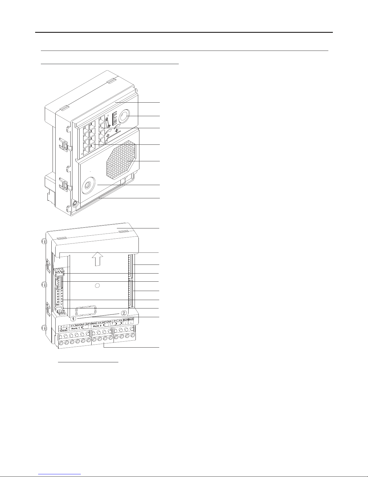
DESCRIPTION OF THE EL632 GB2A SOUND MODULE
Microphone.
Speaker.
Front.
Sound module buttons (x2).
: Positive, negative (12Vdc output for Golmar DC electric lock).
: Contact 'C' for electric lock (Relay 1).
: Contact 'NO' for electric lock (Relay 1).
: Input for exterior door opening button (Relay 1).
: Contact 'NO' for electric lock (Relay 2).
: Contact 'C' for electric lock (Relay 2).
: Input for exterior door opening button (Relay 2).
: Input for exterior call button (button 1).
: Input for exterior call button (button 2).
: Communication BUS (non-polarised).
: Communication BUS (non-polarised).
Colour television camera.
+,
C1
NA1
AP ,AP+
NA2
C2
AP+,AP
P1
P2
BUS
BUS
_
Connection terminals:
LEDs (visual signals for people with impaired hearing).
LEDs (activation in low light conditions).
_
_
Description of the EL632 GB2A sound module:
Terminal strip connector (GB2 Bus).
Button connector (in houses unused).
Back.
Button number.
DIP switch.
Do not use.
Internal use.
Do not use (internal use).
Do not use.
Do not use.
Page 5
5
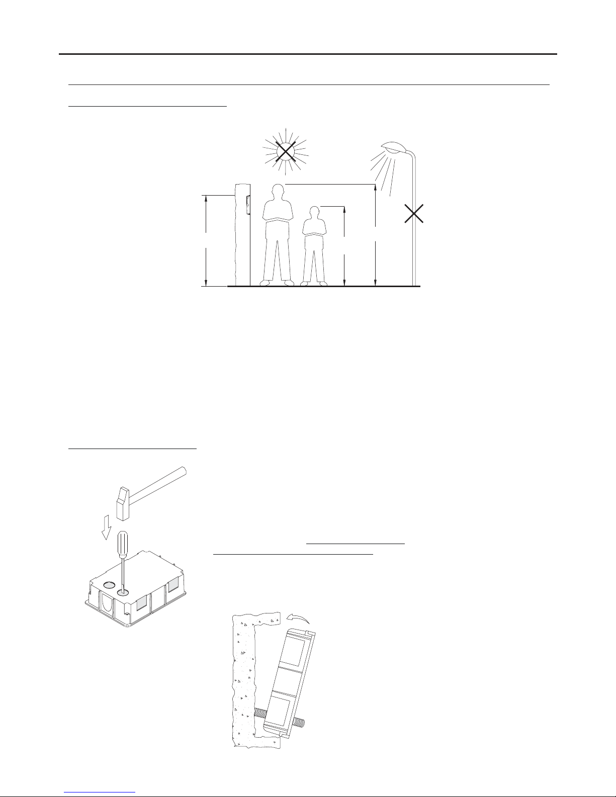
CE-610 embedding box: 125(W) x 140(H) x 56(D) mm.
1650
1850
1450
Make a hole in the wall to position the top of the door panel at a height of 1.65m.
Hole dimensions:
The door panel has been designed to withstand diverse environmental conditions. It is however advisable to
take extra precautions to prolong its service life (shields, covered areas, etc.). To obtain optimum video door
entry system image quality, avoid direct contact from light sources (sunshine, street lights, etc.)
Positioning the embedding box:
STAINLESS STEEL NEXA MODULAR GB2 VIDEO DOOR ENTRY SYSTEM KIT – HOUSES
INSTALLATION OF THE DOOR PANEL
Preparing the cable entry:
Break the flange to allow entry of cables through
the bottom part of the embedding box.
Pass the cable through the hole made
in the embedding box.
Embed the box and ensure that it is
level and flush.
Once embedded, remove the protective
stickers from the screw holes.
Page 6
6
INSTALLATION OF THE DOOR PANEL
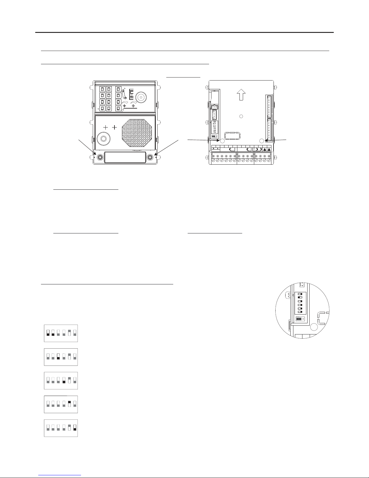
Codes assigned to the call buttons of the sound module:
STAINLESS STEEL NEXA MODULAR GB2 VIDEO DOOR ENTRY SYSTEM KIT – HOUSES
EL632 GB2A
Co s 16 31de - Co s 0 15de -
P1P2 P2
The sound module's P1 and P2 buttons are assigned with factory codes.
- Apartment 1, button 'P1':Assigned with codes 0-15.
Monitors in this apartment must be set with codes in order of allocation from 0 to 15.
When button 'P1' on the door panel is pressed, all of the monitors in apartment 1 will receive the call and only
the monitor assigned with code 0 will show the door panel image. If the call is answered from any other
monitor in the apartment, the image on the monitor assigned with code 0 will disappear and audio and video
communication will be established with the door panel.
- Apartment 2, button 'P2':Assigned with codes 16-31 ( ).only kits with 2 buttons
Monitorsin this apartment must be set with codes in order of allocation from 16 to 31.
When button 'P2' on the door panel is pressed, all of the monitors in apartment 2 will receive the call and only
the monitor assigned with code 16 will show the door panel image. If the call is answered from any other
monitor in the apartment, the image on the monitor assigned with code 0 will disappear and audio and video
communication will be established with the door panel.
Co s 16 31de -
Description of the sound module DIP switch:
1 2 3 4 5 6
ON
+
C1
_
1
The DIP switch is located on the left side of the back of the module.
1 2
3 4 5 6
ON
Door panel address:
DIP switches: 1 and 2 OFF (address 1), 1 ON and 2 OFF (address 2), 1 OFF and
2 ON (address 3), 1 and 2 ON (address 4).
1 2 4 5 6
3
ON
Leave in the OFF position.
1 2 3 5 6
4
ON
Leave in the OFF position for use with door panels in houses and set to ON for
use in apartment buildings.
1 2 3 4 6
5
ON
Leave in the ON position to set the door opening time to 5 seconds. Set to OFF
to set the door opening time to 1 second.
1 2 3 4 5
6
ON
Set to ON to configure: (see pp. 8-9)
Vocal synthesis language, vocal synthesis volume, relay 1 and relay 2 of the lock
release is NO or NC Leave in the OFF position once configuration is complete.
*
( )
*
( )
Factory setting.
*
( )
*
( )
*
( )
*
( )
*
( )
1 2 3 4 5 6
ON
NA2
+
AP-
C1
NA1
AP+C2AP+AP-
P1 P2
BUSBUS
Relay 2
Relay 1
_
12Vdc
1
2
Page 7
7
INSTALLATION OF THE DOOR PANEL
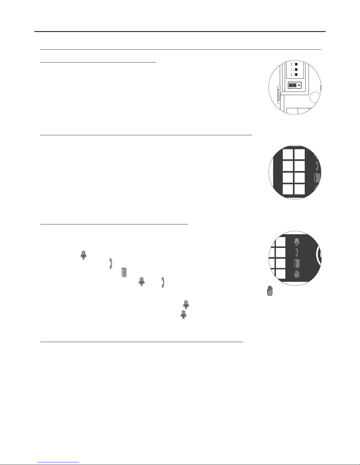
Description of the configuration jumper:
1 2 3 4 5 6
ON
+
C1
_
1
Important: Do not change the configuration jumper's factory position.
Description of the door panel illumination LEDs (for low light conditions):
The door panel lighting LEDs will turn on during a call if the door panel lighting
at that moment is low. This enables the user to view the person who has called
from the apartment monitor.
*
( )
*
( )
Factory setting.
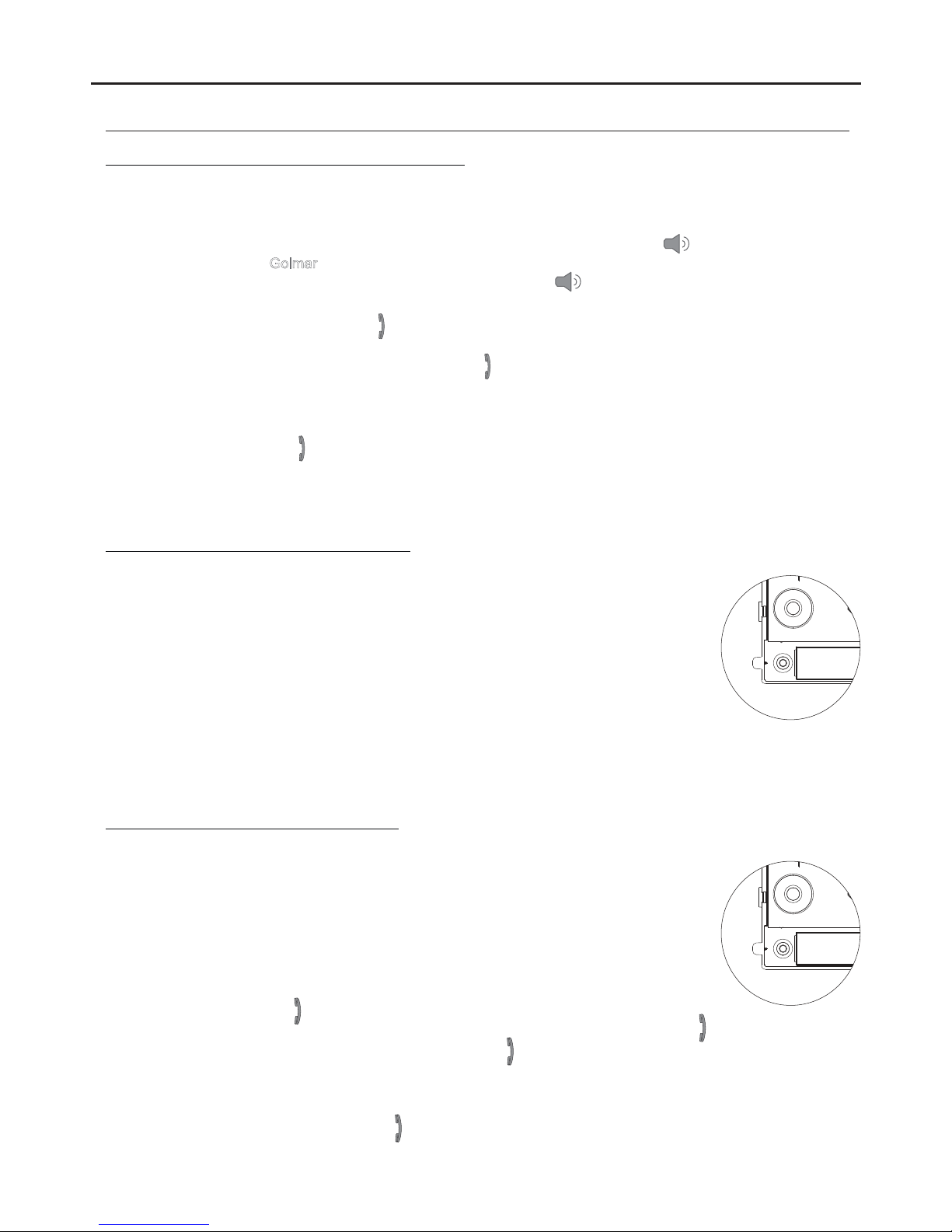
Description of the visual signals on the door panel:
Visual signals on the door panel for people with impaired hearing, indicating:
- In call: LED ' ' will illuminate during in call and in communication times.
- In communication: LED ' ' will illuminate during the communication process.
- When the door is open: LED ' ' will illuminate when the door is open.
- When ending communication: LEDs ' ' and ' ' will turn off.
- With more than one door panel, when calling and one is already in communication: LED ' '
will illuminate for 3 seconds.
.
-
In call and the monitor is in 'Do not disturb' mode: LED ' ' will illuminate for 4 seconds.
- In call (apartment without monitor or telephone): LED ' ' will illuminate for 4 seconds.
Description of the vocal synthesis (audible signals on the door panel):
Audible signals on the door panel for people with impaired vision.
If vocal synthesis is enabled on the sound module (see page 6 and 8 for configuration), the following voice
messages can be heard on the door panel:
- In call: 'Call is in progress'.
- When the door is open: 'Door Opened!'.
- When ending communication: 'Communication is finished'.
- With more than one door panel, when calling and one is already in communication: 'System is busy, try later'.
- While calling and the monitor is in 'Do not disturb' mode: 'Call is in progress'.
- In call (apartment without monitor or telephone): 'Resident Unavailable'.
STAINLESS STEEL NEXA MODULAR GB2 VIDEO DOOR ENTRY SYSTEM KIT – HOUSES
Page 8
8
INSTALLATION OF THE DOOR PANEL
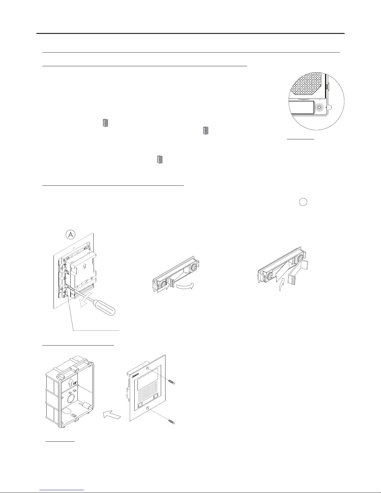
Setting the door panel communication volume:
STAINLESS STEEL NEXA MODULAR GB2 VIDEO DOOR ENTRY SYSTEM KIT – HOUSES
If the audio volume of the door panel is too low after turning it on, follow these steps:
- Call the apartment.
- The call is received in the apartment. Establish communication by pressing option on the screen of the
master monitor or the logo on the front of any slave monitorin the apartment (unless the'display image
' 'Golmar
in call' function is enabled on the slave monitor,in which case, option must be pressed).
- Then press the button used to call the apartment for 3 seconds until a number of confirmation tones are heard
and the door panel communication LED startsto blink.
- Each press on the call button will increase the door panel volume and blink speed of the LED.
There are 5 volume settings and the blink speed of LED will increase for each. Slow to fast blink - low to high
volume. After reaching setting 5, maximum blink speed and volume, the next setting is 1, minimum blink speed
and volume (carousel mode).
- To save the volume setting keep the button pressed until a number of confirmation tones are heard and the door
panel communication LED turns off.
Selecting the vocal synthesis language:
To activate the vocal synthesis of the door panel, followthese steps:
- Disconnect the door panel's power supply.
- Set DIP 6 onthe sound module (see page 6) to ON.
- Reconnect the door panel's power supply.
- Press and hold down button P2 on the sound module for 6 seconds (until the confirmation
tones end).
- Then continue pressing until the required language is reached.
- Finally, set DIP 6 toOFF.
Aconfirmation tone will be heard.
P2
Adjusting the vocal synthesis volume:
If after starting the system the vocal synthesis volume of the door panel seems inadequate,
follow these steps:
- Disconnect the door panel's power supply.
- Set DIP 6 onthe sound module (see page 6) to OFF.
- Reconnect the door panel's power supply.
- Set DIP 6 toON.
- Press and hold down button P2 on the sound modulefor 6 seconds (until the vocal synthesis
volume is heard and LED on the doorpanel starts to blink).
P2
- Then continue pressing to increase the vocal synthesis volume and the blink speed of LED .
There are 5 volume settings and the blink speed of LED will increase for each. Slow to fast blink - low to high
volume. After reaching setting 5, maximum blink speed and volume, the next setting will be 1, minimum blink
speed and synthesis volume (carousel mode). Once the required volume is selected, stop pressing button P2.
- Finally, set DIP 6 toOFF.
Aconfirmation tone will be heard and LED on the door panel will turn off.
Page 9
9
INSTALLATION OF THE DOOR PANEL
Configuring the contact type for Relay 1 and Relay 2 (lock release):
Inserting the push button identification labels:
Open the label holder
window.
Place the label
and close.
Closing the door panel:
Once the door panel has been correctly wired, configured
and adjusted, fix it to the embedding box using the
tamper-proof screws and ¼” tamper-proof screwdriver bit
supplied.
Important:
- Before closing the door panel, make a test call to any apartment to ensure that everything works correctly.
- Keep the tamper-proof screwdriver bit in a safe place in case the door panel needs to be reopened.
STAINLESS STEEL NEXA MODULAR GB2 VIDEO DOOR ENTRY SYSTEM KIT – HOUSES
To insert the push button identification labels, remove the sound module from the door panel to access the label
holder and use a flat screwdriver to gently lever open the fastening clips, as shown in drawing . Once theA
identification labels have been inserted, reattach the sound module to the door panel. Line up the tabs on the sound
module with their respective fastening clips and then press gently until correctly positioned.
*
( )
A
Fastening clips (x4).
P1
To change the contact type for lock release activation of Relay 1 and Relay 2 of the door
panel, follow these steps:
- Disconnect the door panel's power supply.
- Set DIP 6 onthe sound module (see page 6) to ON.
- Reconnect the door panel's power supply.
- Press and hold down button P1 on the sound module for 6 seconds (until the confirmation
tones end and LED on the door panel blinks).
- After this, each press will change the type of contact, LED on the door panel will blink
rapidly if the contact selected is NO (factory setting) or slowly if the contact selected is NC.
Once the required option is selected, stop pressing P1.
- Finally, set DIP 6 toOFF.
Aconfirmation tone will be heard and LED on the door panel will turn off.
Description:
Normally open NO
Normally closed NC
Important: The type of contact selected will be for Relay 1 and Relay 2.
Page 10
10
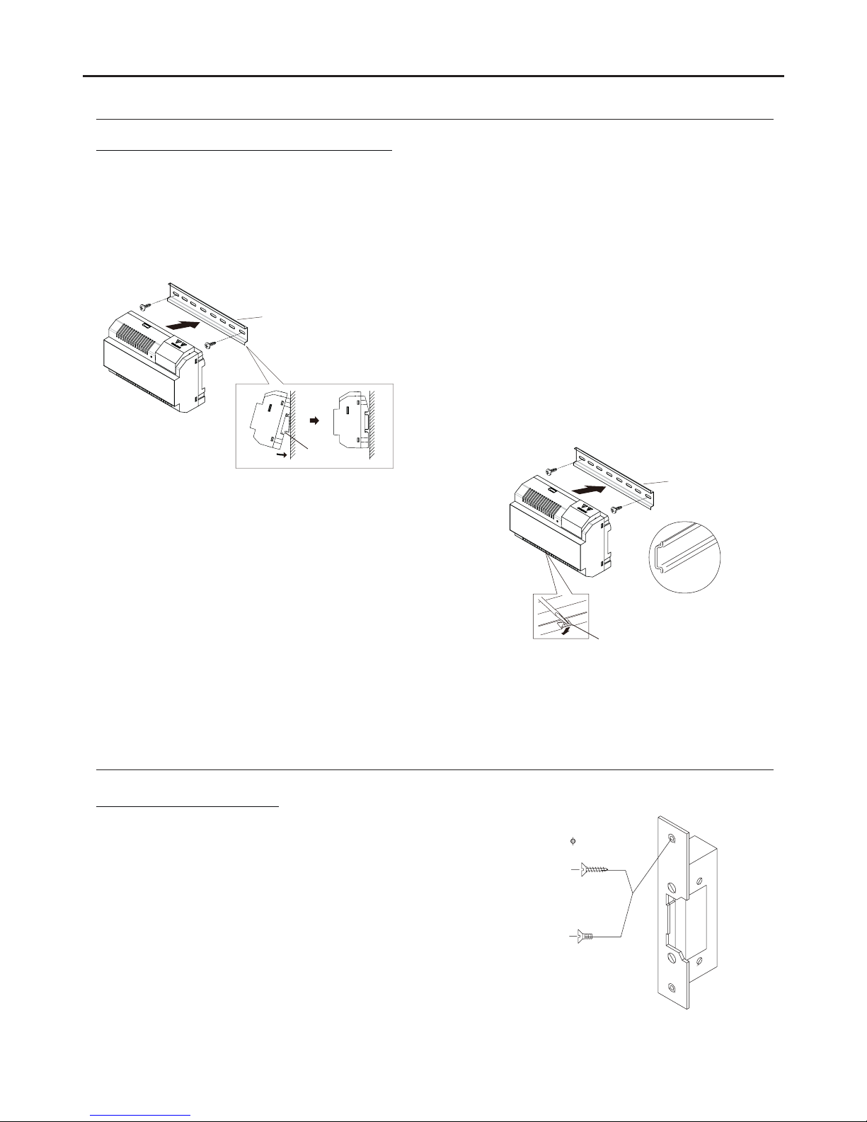
INSTALLATION OF THE POWER SUPPLY UNIT
Installing the FA-GB2/A power supply unit:
M 4 x 8
3,5 x 25
DIN-7972
DIN-963
IMPORTANT:
- The lock release must be 12V DC orAC (Golmar).
(See page 18 forAC lock releases and pages 11-18 for DC lock releases).
- The kit is supplied with two varistors. If connecting an AC lock release to one of the outputs, fit the varistor
supplied directly to the lock release terminals to ensure the device functions correctly.
If the lock release is to be fitted to a metal door, use a Ø3.5mm drill bit and
thread the hole made. For wooden doors, use a Ø3mm drill bit.
Installing the lock release:
INSTALLATION OF THE LOCK RELEASE
STAINLESS STEEL NEXA MODULAR GB2 VIDEO DOOR ENTRY SYSTEM KIT – HOUSES
Replace the protective cover once the input terminals have been wired.
Please note that current regulations stipulate that the power supply
must be protected by a circuit breaker.
Connect the FA-GB2/A power supply unit to the earth connection.
Mount the DIN rail to the wall with the plugs and screws
supplied.
Then attach the power supply by applying slight pressure.
The power supply can be installed on a DIN 46277 rail.
.
To remove the power supply unit from the DIN rail, use a flat
screwdriverto lever it off, as shown in the drawing.
The FA-GB2/Amodel requires 8 elements on the rail.
IMPORTANT: the maximum number of units that can be connected to an FA-GB2/A power supply is
18 PENTHAGB2 monitors.
Install the power supply unit in a dry protected location free from the risk of dripping or splashing water.
To preventelectric shock, do not remove the protective coverof the primary or handle the wiring.
The fitting and handling of this device must be carried out by in the absence of electricalauthorised personnel
current.
To avoid damage, the power supply unit must be firmlysecuredin place.
DIN rail.
DIN rail.
DIN rail.
DIN 46277
DIN rail latch release.
Page 11
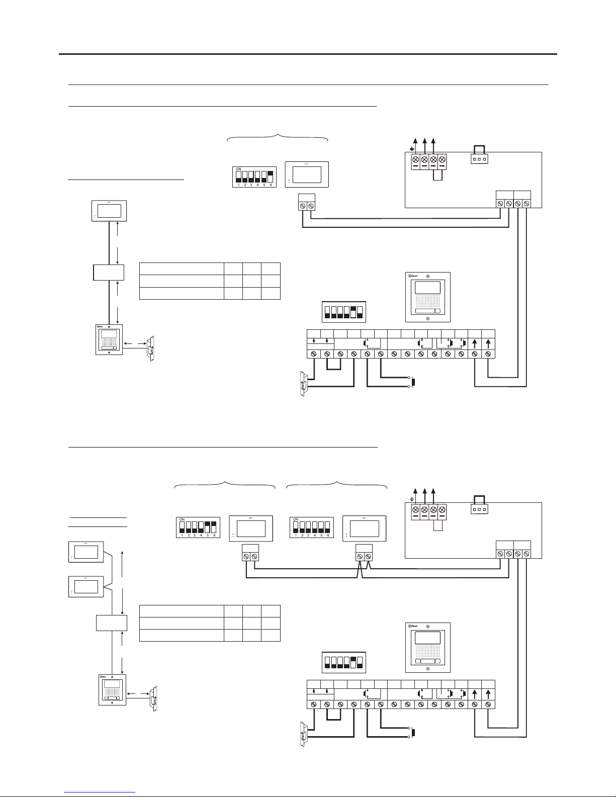
WIRING DIAGRAMS:
One apartment kit (NX5110 PENTHA kit) and Golmar DC lock release.
11
NA2
+
AP-
C1
NA1
AP+
C2
AP+ AP-
P1 P2
BUSBUS
Relay 2
Relay 1
_
12Vdc
Lock release
max
. 12 Vdc/270mA.
N L
CN
Mains
100~240Vac
BUS(M) BUS (PL)
FA- 2GB /A
ON
1 2 3 4 5 6
AP
SW1
( )1
( )1
Access panel
BUS
CODE 0
Two apartment kit (NX5220 PENTHA kit) and Golmar DC lock release.
Configure the end of line in
the last monitor.
DIP 6 to ON.
NA2
+
AP-
C1
NA1
AP+
C2
AP+ AP-
P1 P2
BUSBUS
Relay 2
Relay 1
_
12Vdc
Lock release
max
. 12 Vdc/270mA.
ON
1 2 3 4 5 6
*
AP
SW1
( )1
( )1
Important: For AC lock releases or a second lock release, see diagram 'Connection of Golmar AC and DC lock releases' on p. 18.
( )1
Access panel
BUS
CODE 0
Distances and
cross-sections:
Twisted pair 2x0.75mm
2
Twisted pair 2x1mm
2
60mA60mB10m
C
80m 80m 15m
Cable
BUS
CODE16
FA- 2GB /A
A
B
C
APARTMENT 1APARTMENT 2
*
*
Configure the end of line in
the last monitor.
DIP 6 to ON.
*
Distances and cross-sections:
FA- 2GB /A
A
B
C
APARTMENT 1
STAINLESS STEEL NEXA MODULAR GB2 VIDEO DOOR ENTRY SYSTEM KIT – HOUSES
L
N L
CN
Mains
100~240Vac
BUS(M) BUS (PL)
FA- 2GB /A
L
PENTHA
PENTHA
PENTHAPENTHA
PENTHA
PENTHA
Twisted pair 2x0.75mm
2
Twisted pair 2x1mm
2
60mA60mB10m
C
80m 80m 15m
Cable
Page 12
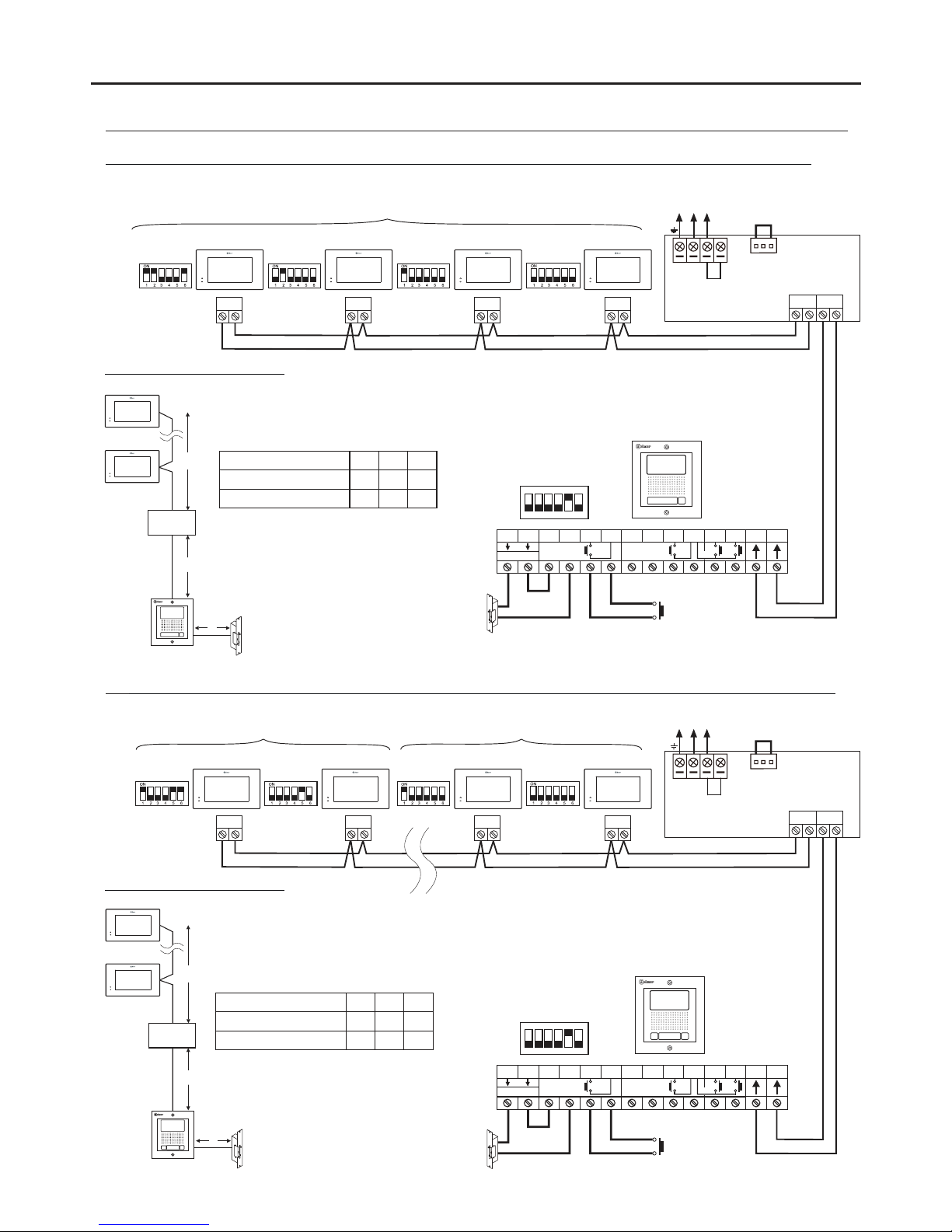
WIRING DIAGRAMS:
One apartment kit (NX5110 PENTHA kit) with monitors in parallel (In-Out) and Golmar DC lock release.
12
Kit Two apartment kit (NX5110 PENTHA kit) with monitors in parallel (In-Out) and Golmar DC lock release.
Configure the end of line in
the last monitor.
DIP 6 to ON.
*
Important: For AC lock releases or a second lock release, see diagram 'Connection of Golmar AC and DC lock releases' on p. 18.
( )1
Distances and cross-sections:
Configure the end of line in
the last monitor.
DIP 6 to ON.
*
Distances and cross-sections:
NA2
+
AP-
C1
NA1
AP+
C2
AP+ AP-
P1 P2
BUSBUS
Relay 2
Relay 1
_
12Vdc
Lock release
max
. 12 Vdc/270mA.
ON
1 2 3 4 5 6
AP
SW1
( )1
( )1
BUS
CODE 1
BUS
CODE 2
BUS
CODE 3
BUS
CODE 0
NA2
+
AP-
C1
NA1
AP+
C2
AP+ AP-
P1 P2
BUSBUS
Relay 2
Relay 1
_
12Vdc
Lock release
max
. 12 Vdc/270mA.
ON
1 2 3 4 5 6
AP
SW1
( )1
( )1
BUS
CODE 1
BUS
CODE 16
BUS
CODE 17
BUS
CODE 0
APARTMENT 1APARTMENT 2
*
*
IMPORTANT: Maximum 4 monitors in parallel (without distributors) per installation.
IMPORTANT: Maximum 4 monitors in parallel (without distributors) per installation.
APARTMENT 1
STAINLESS STEEL NEXA MODULAR GB2 VIDEO DOOR ENTRY SYSTEM KIT – HOUSES
N L
CN
Mains
100~240Vac
BUS(M) BUS (PL)
FA- 2GB /A
L
N L
CN
Mains
100~240Vac
BUS(M) BUS (PL)
FA- 2GB /A
L
Access panel
A
B
C
FA- 2GB /A
Access panel
A
B
C
FA- 2GB /A
PENTHA
PENTHA
PENTHAPENTHAPENTHA
PENTHA
PENTHAPENTHAPENTHAPENTHA
PENTHA
PENTHA
Twisted pair 2x0.75mm
2
Twisted pair 2x1mm
2
60mA60mB10m
C
80m 80m 15m
Cable
Twisted pair 2x0.75mm
2
Twisted pair 2x1mm
2
60mA60mB10m
C
80m 80m 15m
Cable
Page 13
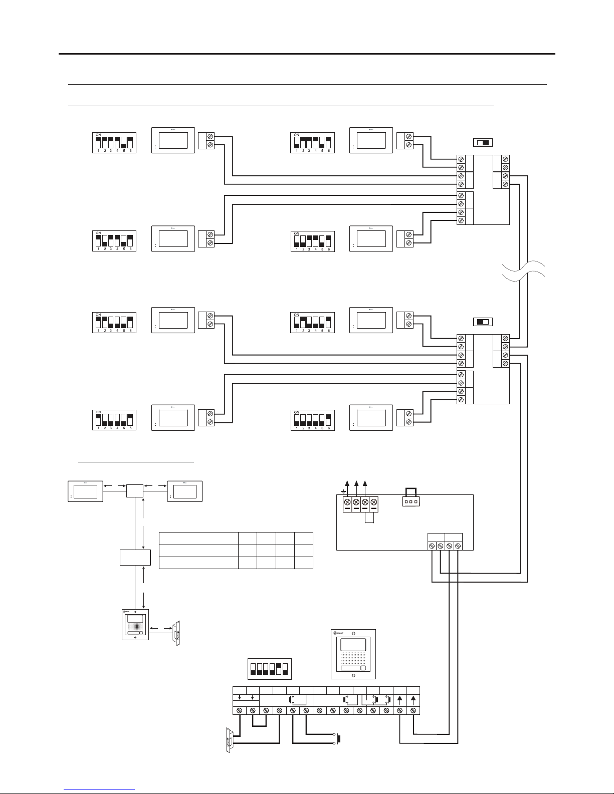
WIRING DIAGRAMS:
One apartment with 16 PENTHA monitors, 4 DP-GB2A distributors and Golmar DC lock release.
13
Configure the end of line in
the last monitor.
DIP 6 to ON.
Access panel
**
Lock release
max
. 12 Vdc/270mA.
BUS
BUS
BUS
BUS
BUS
BUS
BUS BUS
D
C
B
A
DP-GB2A
BUS
BUS
End of line
ON
End of line
OFF
CODE 3 CODE 2
CODE 1
CODE 13
CODE 12
**
**
** **
**
CODE 0
**
Configure the end of line in
the last distributor.
Switch to ON.
*
*
AP
Distances and cross-sections:
DP-GB2A
A
C
B
C
Important: For AC lock releases or a second lock release, see diagram 'Connection of Golmar AC and DC lock releases' on p. 18.
(1)
(1)
NA2
+
AP-
C1
NA1
AP+
C2
AP+ AP-
P1 P2
BUSBUS
Relay 2
Relay 1
_
12Vdc
ON
1 2 3 4 5 6
SW1
(1)
BUS
BUS
BUS BUS
D
C
B
A
DP-GB2A
D
Twisted pair 2x0.75mm
2
Twisted pair 2x1mm
2
60mA60mB30m
C
80m 80m 40m
Cable
10m
D
15m
STAINLESS STEEL NEXA MODULAR GB2 VIDEO DOOR ENTRY SYSTEM KIT – HOUSES
FA- 2GB /A
N L
CN
Mains
100~240Vac
BUS(M) BUS (PL)
FA- 2GB /A
L
BUS
BUS
CODE 15 CODE 14
** **
PENTHA
PENTHA
PENTHA
PENTHA
PENTHA
PENTHA
PENTHA
PENTHA
PENTHA PENTHA
Page 14
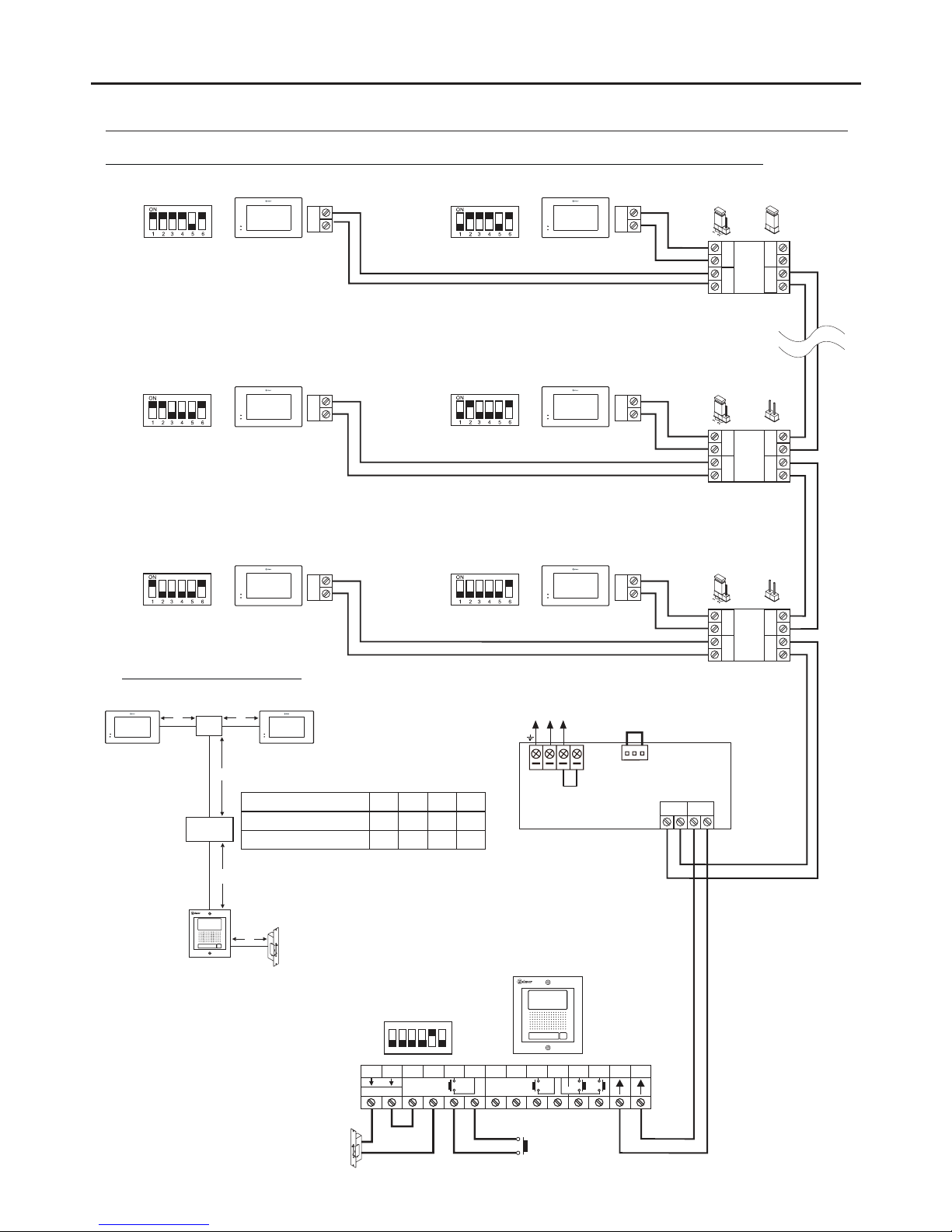
WIRING DIAGRAMS:
One apartment with 16 PENTHA monitors, 8 D2L-GB2 distributors and Golmar DC lock release.
14
Configure the end of line in
the last monitor.
DIP 6 to ON.
**
NA2
+
AP-
C1
NA1
AP+
C2
AP+ AP-
P1 P2
BUSBUS
Relay 2
Relay 1
_
12Vdc
Lock release
max
. 12 Vdc/270mA.
BUS
BUS
BUS BUS
D2
D1
D2L- 2GB
ON
1 2 3 4 5 6
BUS
BUS
BUS
BUS
BUS BUS
D2
D1
D2L-GB2
BUS
End of
line
ON
CODE 3 CODE 2
** **
Remove the jumper from all
of the distributors except
the last.
*
*
AP
SW1
BUS
BUS
BUS BUS
D2
D1
D2L- 2GB
BUS
BUS
CODE 1 CODE 0
** **
OFF
(1)
End of
line
OFF
End of
line
(1)
(1)
Distances and cross-sections:
(2)
(2)
Twisted pair 2x0.75mm
2
Twisted pair 2x1mm
2
60mA60mB30m
C
80m 80m 40m
Cable
10m
D
15m
Important: For AC lock releases or a second lock release, see diagram 'Connection of Golmar AC and DC lock releases' on p. 18.
( )2
CODE 15
**
Access panel
STAINLESS STEEL NEXA MODULAR GB2 VIDEO DOOR ENTRY SYSTEM KIT – HOUSES
D -2L GB2
A
C
B
C
D
FA- 2GB /A
N L
CN
Mains
100~240Vac
BUS(M) BUS (PL)
FA- 2GB /A
L
BUS
CODE 14
**
PENTHA
PENTHA
PENTHA
PENTHA
PENTHA
PENTHA
PENTHA PENTHA
Set the jumper in this position for
7” GB2 monitors of all of the
D2L-GB2 distributors.
.
(1)
Page 15
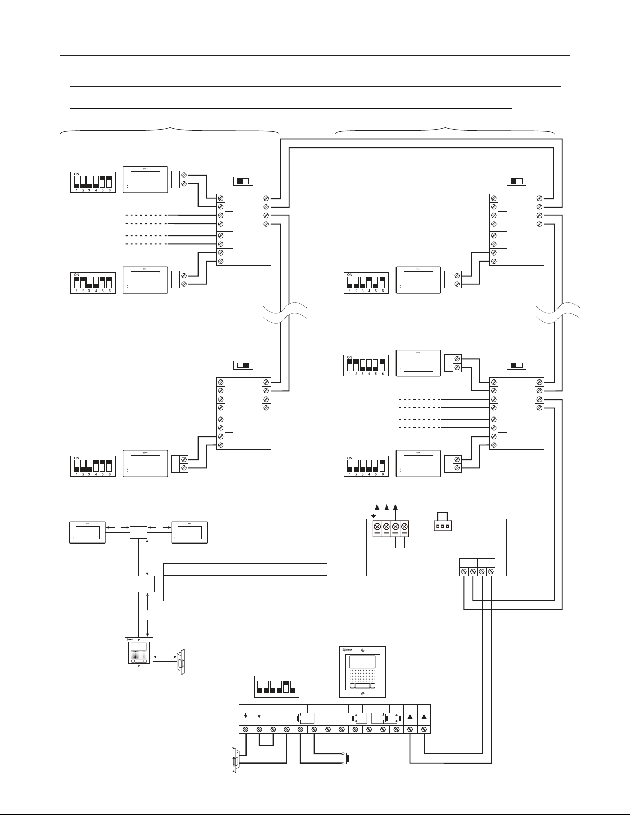
WIRING DIAGRAMS:
Two apartments with 18 PENTHA monitors, 5 DP-GB2A distributors and Golmar DC lock release.
15
Configure the end of line in
the last monitor.
DIP 6 to ON.
**
Lock release
max
. 12 Vdc/270mA.
BUS
BUS
BUS
BUS
BUS BUS
D
C
B
A
DP-GB2A
BUS
End of line
End of line
OFF
CODE 3
CODE 0
CODE 8
**
**
**
Configure the end of line in
the last distributor.
Switch to ON.
*
AP
Distances and cross-sections:
DP-GB2A
A
C
B
C
Important: For AC lock releases or a second lock release, see diagram 'Connection of Golmar AC and DC lock releases' on p. 18.
(1)
(1)
NA2
+
AP-
C1
NA1
AP+
C2
AP+ AP-
P1 P2
BUSBUS
Relay 2
Relay 1
_
12Vdc
ON
1 2 3 4 5 6
SW1
(1)
BUS
BUS
BUS BUS
D
C
B
A
DP-GB2A
D
Twisted pair 2x0.75mm
2
Twisted pair 2x1mm
2
60mA60mB30m
C
80m 80m 40m
Cable
10m
D
15m
MONITOR 1
MONITOR 2
**
**
BUS
BUS
BUS
BUS BUS
D
C
B
A
DP-GB2A
BUS
BUS
End of line
End of line
CODE 24
CODE 16
CODE 19
**
**
**
*
BUS
BUS
BUS BUS
D
C
B
A
DP-GB2A
MONITOR 18
MONITOR 17
**
**
OFF
ON
OFF
APARTMENT 2 APARTMENT 1
STAINLESS STEEL NEXA MODULAR GB2 VIDEO DOOR ENTRY SYSTEM KIT – HOUSES
N L
CN
Mains
100~240Vac
BUS(M) BUS (PL)
FA- 2GB /A
L
FA- 2GB /A
Access panel
PENTHA
PENTHA PENTHA
PENTHA PENTHA
PENTHA PENTHA
PENTHA
Page 16
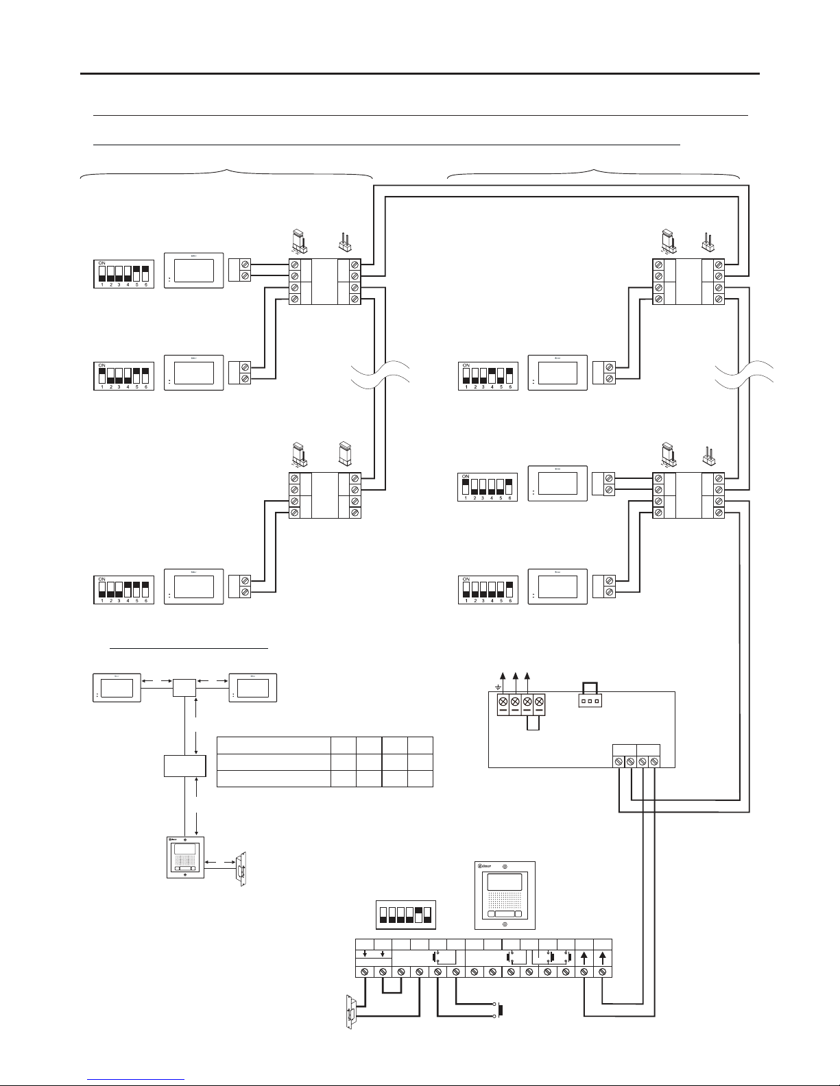
WIRING DIAGRAMS:
Two apartments with 18 PENTHA monitors, 9 D2L-GB2 distributors and Golmar DC lock release.
16
Configure the end of line in
the last monitor.
DIP 6 to ON.
**
NA2
+
AP-
C1
NA1
AP+
C2
AP+ AP-
P1 P2
BUSBUS
Relay 2
Relay 1
_
12Vdc
Lock release
max
. 12 Vdc/270mA.
ON
1 2 3 4 5 6
BUS
BUS
BUS BUS
D2
D1
D2L-GB2
Remove the jumper from all
of the distributors except
the last.
*
AP
SW1
BUS
BUS
BUS BUS
D2
D1
D2L- 2GB
OFF
End of
line
Distances and cross-sections:
D2L- 2GB
A
C
B
C
(2)
(2)
Twisted pair 2x0.75mm
2
Twisted pair 2x1mm
2
60mA60mB30m
C
80m 80m 40m
Cable
10m
D
15m
D
Important: For AC lock releases or a second lock release, see diagram 'Connection of Golmar AC and DC lock releases' on p. 18.
( )2
BUS
BUS
BUS
CODE 1
CODE 0
CODE 8
**
**
**
BUS
BUS
BUS
CODE 24
CODE 16
CODE 17
**
**
**
APARTMENT 2
BUS
BUS
BUS BUS
D2
D1
D2L-GB2
End of
line
ON
*
BUS
BUS
BUS BUS
D2
D1
D2L- 2GB
OFF
End of
line
OFF
End of
line
STAINLESS STEEL NEXA MODULAR GB2 VIDEO DOOR ENTRY SYSTEM KIT – HOUSES
N L
CN
Mains
100~240Vac
BUS(M) BUS (PL)
FA- 2GB /A
L
Access panel
FA- 2GB /A
APARTMENT 1
PENTHA
PENTHA PENTHA
PENTHA PENTHA
PENTHA PENTHA
PENTHA
Set the jumper in this position for
7” GB2 monitors of all of the
D2L-GB2 distributors.
(1)
(1)(1)
(1)(1)
Page 17
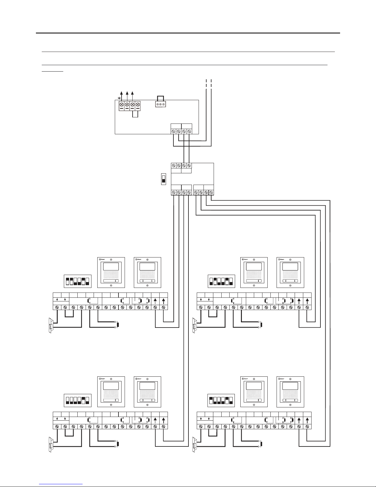
WIRING DIAGRAMS:
17
BUSBUS
BUS BUS
D C B A
DP-GB2A
End of line
OFF
AP AP
Access panel 2
ON
1 2 3 4 5 6
SW1
Access panel 1
ON
1 2 3 4 5 6
SW1
AP AP
Access panel 3
ON
1 2 3 4 5 6
SW1
Access panel 4
ON
1 2 3 4 5 6
SW1
(1) (1)
(1) (1)
To the distributors (building floors)
Lock release
max
. 12 Vdc/270mA.
Lock release
max
. 12 Vdc/270mA.
Lock release
max
. 12 Vdc/270mA.
Lock release
max
. 12 Vdc/270mA.
NA2
+
AP-
C1
NA1
AP+
C2
AP+ AP-
P1 P2
BUSBUS
Relay 2
Relay 1
_
12Vdc
NA2
+
AP-
C1
NA1
AP+
C2
AP+ AP-
P1 P2
BUSBUS
Relay 2
Relay 1
_
12Vdc
NA2
+
AP-
C1
NA1
AP+
C2
AP+ AP-
P1 P2
BUSBUS
Relay 2
Relay 1
_
12Vdc
NA2
+
AP-
C1
NA1
AP+
C2
AP+ AP-
P1 P2
BUSBUS
Relay 2
Relay 1
_
12Vdc
Important: For AC lock releases or a second lock release, see diagram 'Connection of Golmar AC and DC lock releases' on p. 18.
(1)
(1)
(1)
(1)
(1)
Video door entry system with 4 access panels, DP-GB2A distributor for door panels and Golmar DC lock
release.
STAINLESS STEEL NEXA MODULAR GB2 VIDEO DOOR ENTRY SYSTEM KIT – HOUSES
N L
CN
Mains
100~240Vac
BUS(M) BUS (PL)
FA- 2GB /A
L
or
or
oror
Page 18
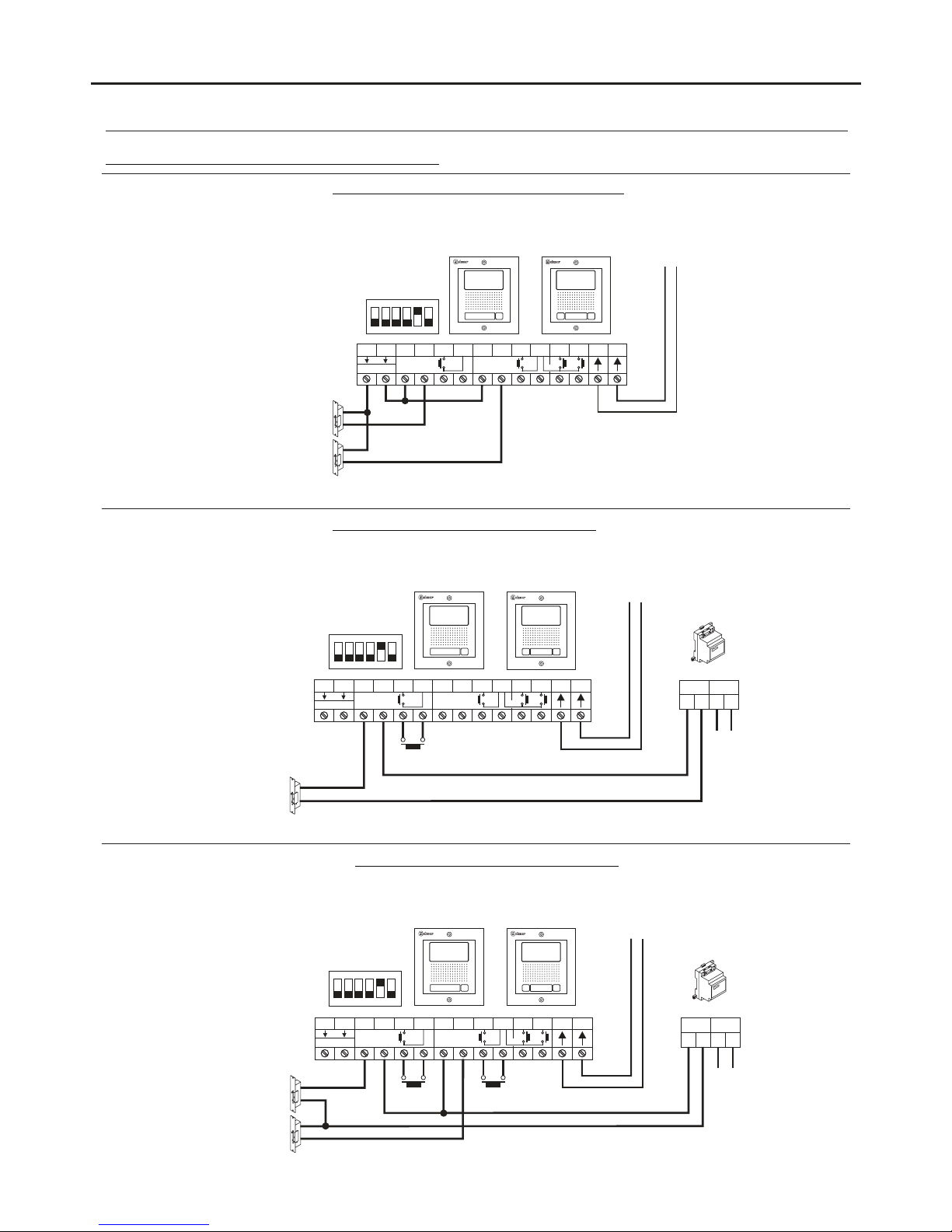
Access panel
ON
1 2 3 4 5 6
SW1
NA2
+
AP-
C1
NA1
AP+
C2
AP+ AP-
P1 P2
BUSBUS
_
AP1
NA2
+
AP-
C1
NA1
AP+
C2
AP+ AP-
P1 P2
BUSBUS
Relay 2Relay 1
_
12Vdc
Connection of 2 DC lock releases without 'AP':
Important: With 2 DC lock releases, it is not possible to use the “AP” door release buttons.
(1)
Mains
230Vac
SEC
~~ ~~
PRI
TF-104
Lock release
max
. 12 Vac/850mA.
Connection of 1 AC lock release with 'AP':
NA2
+
AP-
C1
NA1
AP+
C2
AP+ AP-
P1 P2
BUSBUS
Relay 2Relay 1
_
12Vdc
(1)
To the FA-GB2/A
power supply
(1)
Lock release
max
. 12 Vdc/270mA.
Connection of 2 AC lock release with 'AP':
SEC
PRI
TF-104
Access panel
ON
1 2 3 4 5 6
SW1
Access panel
ON
1 2 3 4 5 6
SW1
WIRING DIAGRAMS:
18
Relay 2Relay 1
12Vdc
Lock release
max
. 12 Vac/850mA.
~~ ~~
AP1 AP2
Mains
230Vac
Connection of Golmar DC and AC lock releases.
STAINLESS STEEL NEXA MODULAR GB2 VIDEO DOOR ENTRY SYSTEM KIT – HOUSES
or
or
To the FA-GB2/A
power supply
or
To the FA-GB2/A
power supply
Important: Fit the varistor supplied with the kit directly to the terminals of the lock release.
Important: Fit the varistor supplied with the kit directly to the terminals of each of the 2 lock releases.
*
*
*
*
*
Page 19

NOT S:E
19
STAINLESS STEEL NEXA MODULAR GB2 VIDEO DOOR ENTRY SYSTEM KIT – HOUSES
Page 20
www.golmar.es
Sistemas de comunicaciónS.A.
Golmar se reserva el derecho a cualquier modificación sin previo aviso.
Golmar se réserve le droit de toute modification sans préavis.
Golmar reserves the right to make any modifications without prior notice.
GOLMAR S.A.
C/ Silici, 13
08940- Cornellá de Llobregat
SPAIN
 Loading...