

Page 1
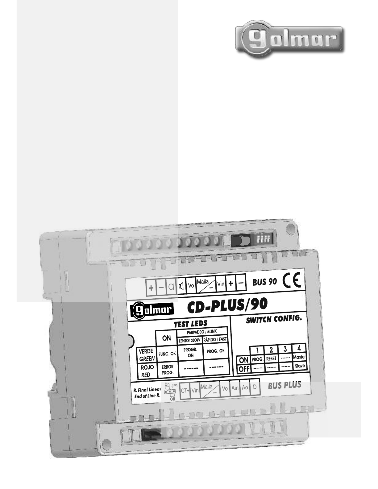
CD-PLUS/90
Protocol
converter
Instructions manual
TCD-PLUS/90ML rev.0112
Cód. 50121600
Page 2
2
INTRODUCTION
SYSTEM CHARACTERISTICS
First of all we would like to thank and congratulate you for the purchase of this product manufactured by
The commitment to reach the satisfaction of our customers is stated through the ISO-9001 certification
and for the manufacturing of products like this one.
Its advanced technology and exacting quality control will do that customers and users enjoy with the
legion of features this system offers To obtain the maximum profit of these features and a properly wired
installation, we kindly recommend you to expend a few minutes of your time to read this manual.
Golmar.
.
SAFETY PRECAUTIONS
O Protocol converter to 90 system which permits the following functions:
ÜPermits replace a faulty 90 door panel by a Plus door panel.
ÜPermits installation of Plus general door panels with inner access in the 90 system.
ÜPermits installation of a Plus coded door panel with 90 monitors/telephones.
O Up to 250 converters per installation.
O Simple configuration through easy access dip switches.
O End of line configuration jumper JP1.
O Autodiagnostic LEDs that allow detecting operation and programming errors.
O The converter is factory set with backbone address "0".
O Connection block to 90 system (video connection with Coaxial cable).
O Connection block to Plus system (video connection with Coaxial cable).
O EL564 transceiver to convert video signal from twisted pair to coaxial and from coaxial to twisted pair.
O
O Specific Power supply not needed for this converter, it takes of the 90 system installation the supplies
voltage (24Vdc).
Permits installation of a Plus porter's exchange only in the side Plus system installation.
O The installation and handling of the converter must be performed by authorized personnel and in
the absence of electrical current.
O Do not use excessive force when tightening the converter connection block screws.
O .
O Install the converter in a dry and protected place without risk of drip or water projections.
O Avoid placing the converter near sources of heat, in dusty locations or smoky environments.
O Do not block ventilation holes of the unit so that air can circulate freely.
O To avoid damage, the converter has to be firmly fixed.
The entire installation must be at least 40cm away from any other installation
STARTING RECOMMENDATIONS
O Do not use excessive force when tightening the converter connection block screws.
O Before connecting the system, check the connections between door panel, converter, transceiver,
monitors, telephones and the power supply connection.
O .
O Always follow the instructions of this manual.
The entire installation must be at least 40cm away from any other installation
Page 3
3
OPERATION MODES
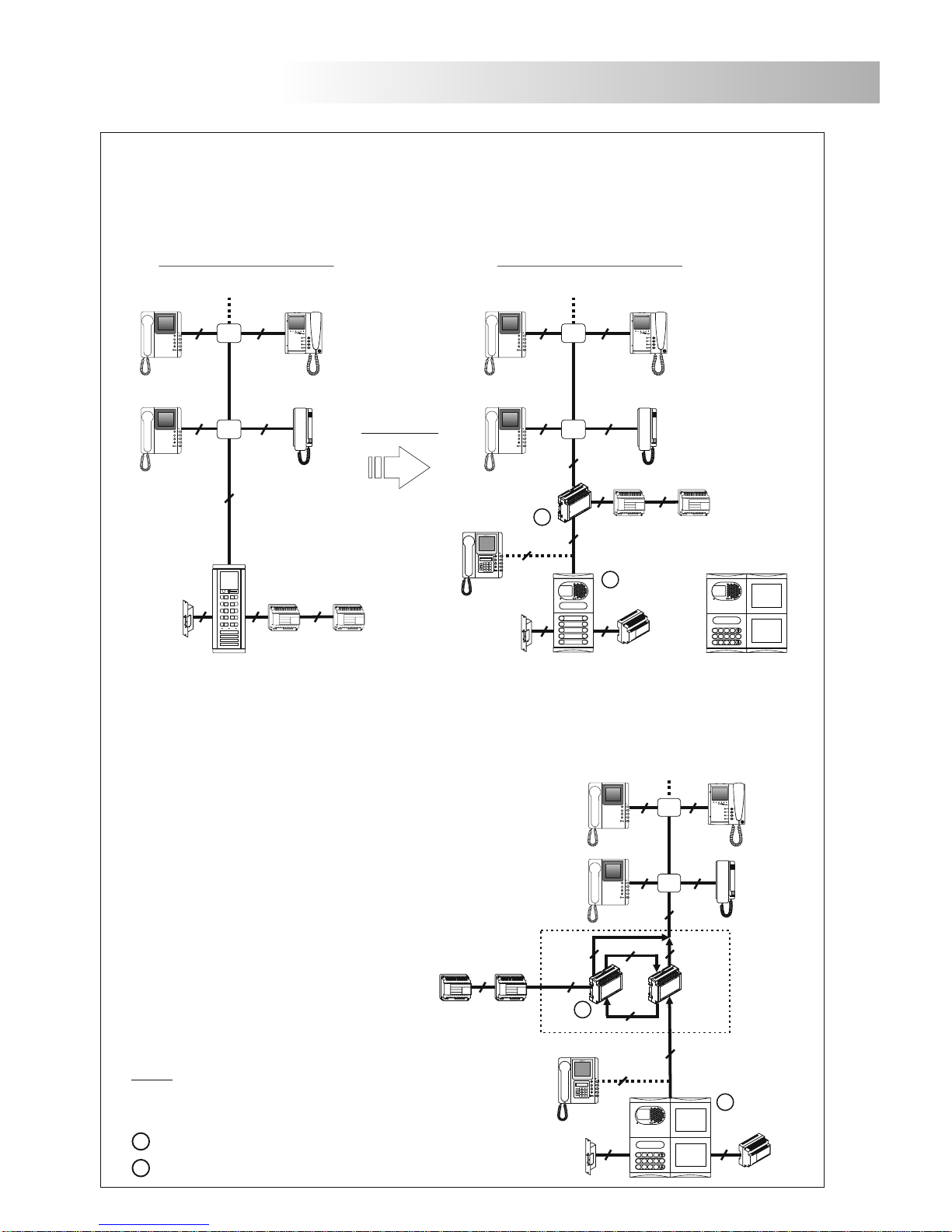
Transceiver module for video signal.
The transceiver module for video signal EL-564 converts a
twisted pair to coaxial and vice versa. This module is necessary in
a system with 4+TP installation and to convert the twisted pair to
coaxial, and therefore connect the video signal in the protocol
converter CD-Plus/90 of the entrance coaxial. There is an
option to place a CE-990 Plus porter's exchange between the
converter and the Plus door panel.
Installation diagrams on pages 40, 43, 44 and 46.
CD-Plus/90
22
1
5
9
2
6
0
3
7
C
4
8
Central de conserjería
Porter's exchange
0
0
C
ancel
C
ancel
7
7
889
9
112
2
3
3
4
4
5
5
6
6
o.k.
o.k.
Lock release
4 + TP
Plus porter's
exchange
Next
monitors
FA-PLUS/C
Plus coded door panel
3 + TP
EL-564
Replacement in a 90 system.
Permits replace a faulty 90 door panel by a Plus door panel, the Plus door panel installed will be
connected to the 90 system through the protocol converter CD-Plus/90. There is an option to
place a CE-990 Plus porter's exchange between the converter and the Plus door panel.
Installation diagrams on pages 38 to 46.
2
FA-PLUS/C
2
Plus door panel
A-490/1 A-490/2
2
Shiner 90
Shiner 90
T-840
Platea 90
4+TP
4
Coax
3+Coax
2
TP
M
4+TP
4+TP4+TP
M
90 system with 90 door panel
4
3+Coax
2
A-490/2
4
PV-90 door panel
Shiner 90
T-840
3+Coax
3+Coax
Shiner 90
STOP
4
A-490/1
3+Coax
90 system with Plus door panel
4
3+Coax
3+Coax
Shiner 90
T-840
3+Coax
3+Coax
Shiner 90
3+Coax
Platea 90 Platea 90
A-490/2
2
2
A-490/1
CD-Plus/90
M
M
1
5
9
2
6
0
3
7
C
4
8
or
Plus coded door panel
Central de conserjería
Porter's exchange
0
0
C
ancel
C
ancel
7
7
889
9
112
2
3
3
4
4
5
5
6
6
o.k.
o.k.
3 + Coax
Plus porter's
exchange
For other configurations of replacement contact with your distributor.
Replacement
Next
monitors
Next
monitors
Lock release
Lock release
M =Master.
S =Slave.
Terms:
Backbone
Riser: Physical cabling of the installation
in the same backbone (logical address).
: Logical address.
*
4
Page 4
4
DESCRIPTION
INSTALLATION
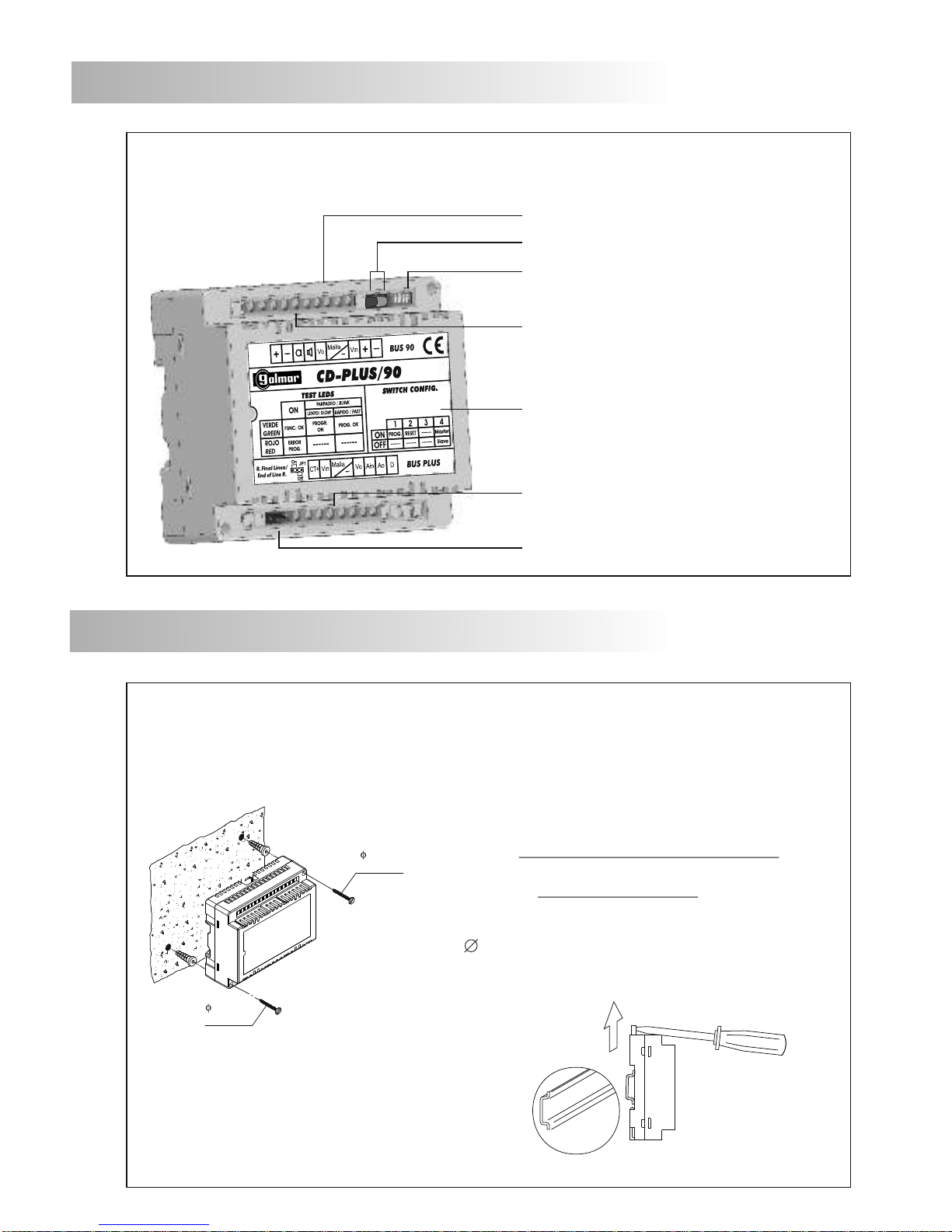
etail of the converter installation.
D
the converter can be installed on a DIN
guide (6 elements), pressing it lightly.
To extract the converter from the DIN guide,
use a plain screwdriver to lever the flange as
shown in the picture.
Install the converter in a dry and protected place without risk of drip or water projections.
To avoid damage, the conveter must be firmly fixed.
DIN 46277
To install the converter directly on the wall, drill two holes
of 6mm. and insert the wallplugs. Fix the converter
with the specified screws.
escription of the converter.
D
DIN rail latch release
Autodiagnostic LEDs
Configuration dip switch
Plus Bus connection block
90 Bus connection block
Label
The installation or modification the converter,
performed
must be
in the absence of electrical current.
The installation and handling of the converter must be
performed by authorized personnel.
End of line configuration jumper JP1
3,5 x 50
DIN-7971
3,5 x 50
DIN-7971
Page 5
5
CONFIGURATION
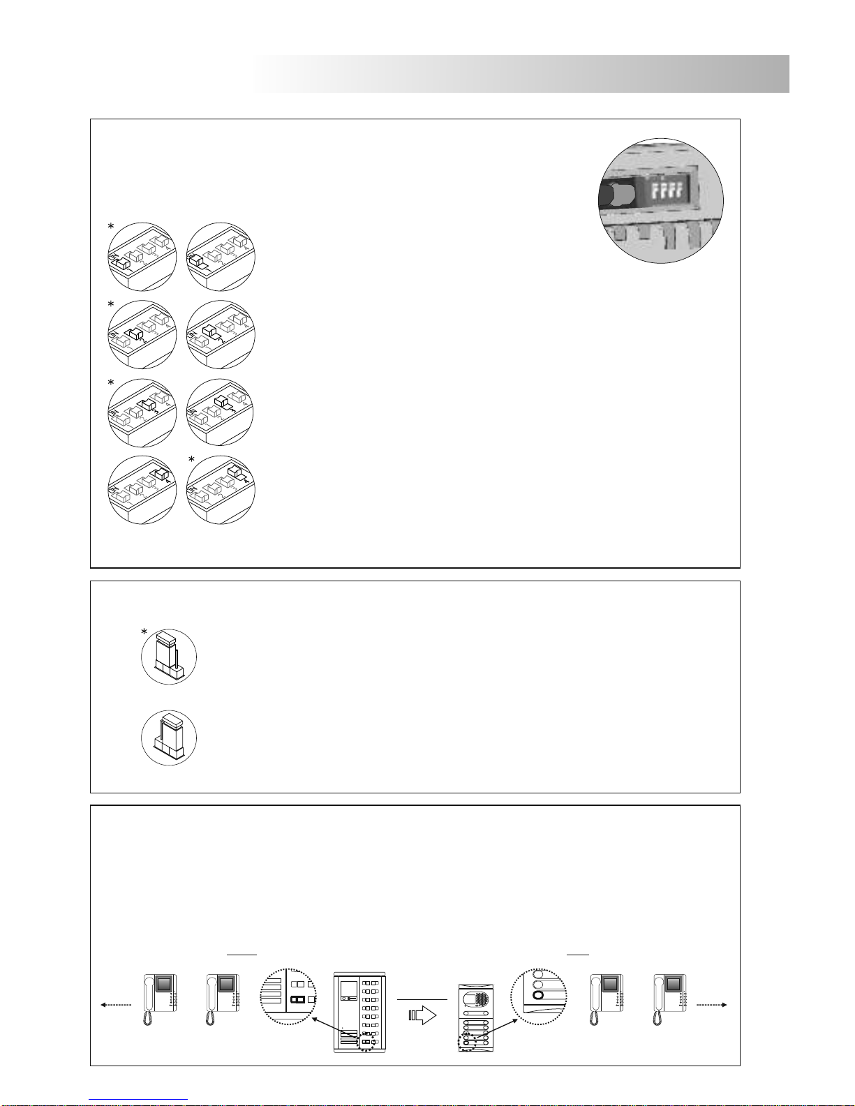
escription of the configuration dip switch.
D
The SW1 configuration dip switch is located on
the upper right part of the module.
Set to ON to programme the backbone.
Once the programming has finished, return the switch
to the OFF position.
*Factory default
No function.
Set to ON (Master) to charge the installation with a resistance of
communications. Only activate this resistance in the converter CD-
Plus/90 or in the 90 door panel closest to the installation riser.
Set to OFF (Slave) if the resistance of communications is activated in the
90 door panel closest to the installation riser.
escription of the configuration jumper.
D
On
Off
JP1
JP1
End of line resistor.
Switch to Off in all the converters except the last one if the connection to the Plus
system of the converters does not contain distributors (input/output mode).
End of line resistor.
Switch to On if the converter is connected to the Plus system through distributors or
only in the last converter if the connection to the Plus system of the converters does
not contain distributors (input/output mode)
*Factory default
To reset the converter, switch to ON (all leds Off) and then set to OFF (green
led On), after an operation or programming errors.
odification of the push-buttons/monitors in a replacement.
C
To replace a 90 door panel in an installation with Plus door panel, it must be borne in mind the
codification of the first push-button of the Plus door panel and the configured address in the monitor
linked to this push button, for the reason that 90 door panel has a call code address linked to the first
push button as "00", therefore should be set the first push button and the monitor of the apartment with
address "00" with another free address "XX".
90 door panel
Plus door panel
Replacement
STOP
1 Push button
address "00"
st
1 Push button
address "XX"
st
Shiner 90
1 Apartment
address "00"
nd
Shiner 90
1 Apartment
address "XX"
st
Before After
Shiner 90
2 Apartment
address "01"
st
Shiner 90
2 Apartment
address "01"
nd
Next
monitors
Next
monitors
Page 6
AUTODIAGNOSTIC LEDS
PROGRAMMING
6
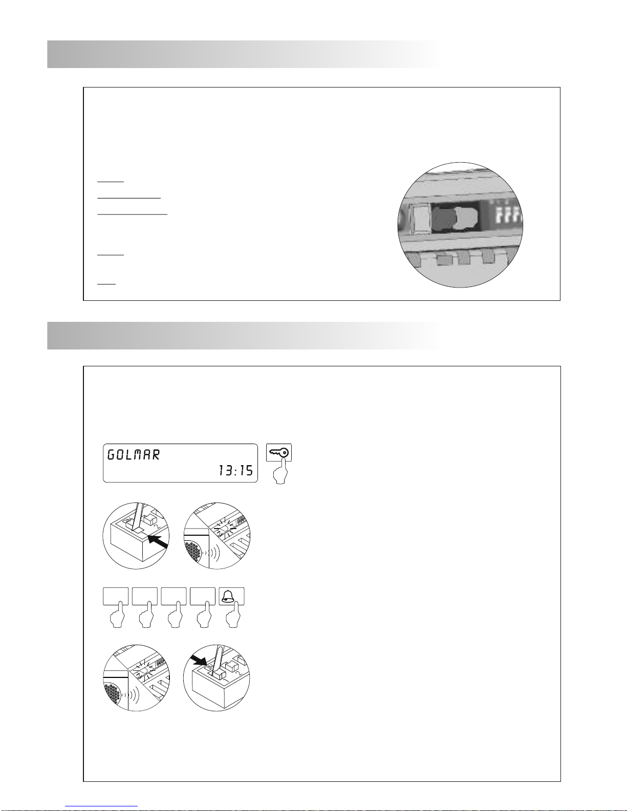
escription of autodiagnostic LEDs.
D
The autodiagnostic LEDs are placed next
to the configuration dip switch.
Red Led
Fixed: Programming error, restart programming from the
beginning.
Off: Correct operation.
Green Led
Fixed: Correct operation.
Slow blinking: Programming active (SW1-1 to ON).
Quick blinking: Programming finished.
P
rogramming the converter.
The converter must be programmed with a backbone code (see pages 41 to 44), which must be
different for each converter, following the steps set out below.
Introduce the backbone code to program, followed by three
zeros, then press the bell button.
O.K.
0 0 01
Activate the converter programming by setting dip switch
number 1 to ON.
The door panel will emit a tone and the green LED on the
converter will begin to blink slowly, indicating that
programming has begun.
To indicate that the equipment has been correctly programmed,
the door panel will emit a tone and the green LED on the
converter will begin to quick blinking.
Exit programming by setting dip switch number 1 to OFF and
pressing the C button on the door panel"Cancel" .
If there are more converters, repeat the previous steps introducing a different backbone code for
each of them.
If during one of these processes the red LED on the converter switches on, restart programming from
the beginning.
To access the door panel programming mode, press
the key button followed by the secret installer
code (factory default 1315), just as indicated in
the door panel manual.
Page 7
7
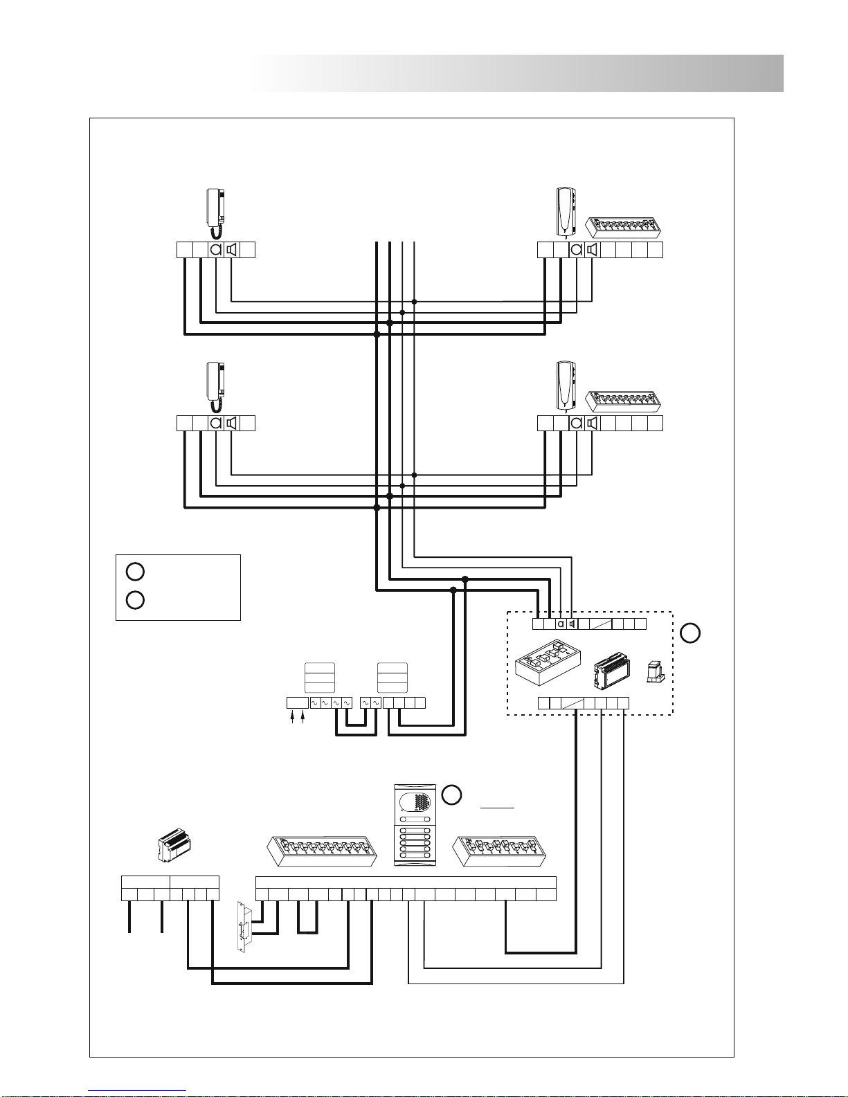
INSTALLATION DIAGRAMS
Replacement in a 90 system mode (audio installation).
IMPORTANT: To configure and to program each equipment see the appropiate instruction book.
Main
M =Master.
S =Slave.
M
Plus door panel
For other configurations of replacement contact with your distributor.
M
T-840 T-790VD
T-840
_
+
SA
_
+
SA
T-790VD
HZ
_
+
HZ
_
+
Next
Distributor
SW2
SW2
SW2 SW1
D
Malla
Vin-AinAout Vin+ Vout-Vout+
CN2
+AP
- -
+
CV1CV2-+12
-
+
-
230 110 0
-
+
SEC
PRI
FA- PLUS/C
ver. 938072
DAo
Ain
Vi
CT+
Vo
+
CD-PLUS/90
PLUS BUS
90 BUS
-
JP1
ViVo
+
-
Malla
-
Malla
-
A-490/1
N R
+
-
2
0 220
PRI
1
A-490/2
_
+
SA
_
+
SA
EL500SE
Page 8
8
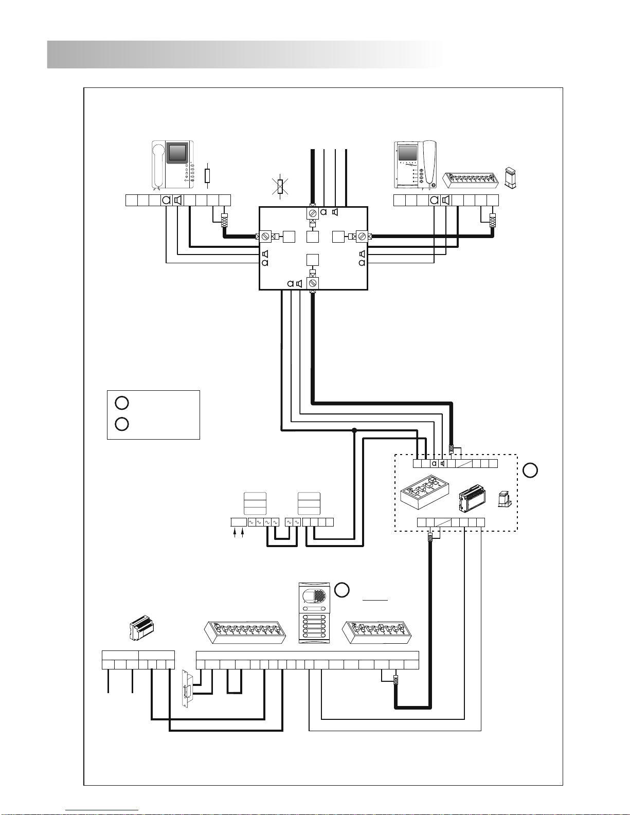
INSTALLATION DIAGRAMS
Replacement in a 90 system mode (video installation with coaxial cable).
IMPORTANT: To configure and to program each equipment see the appropiate instruction book.
Main
PLUS BUS
90 BUS
M =Master.
S =Slave.
M
M
Next
Distributor
Plus door panel
**
Configuring the end of
line in the last monitor.
Cut the resistor in all
distributors except in
the last one.
*
For other configurations of replacement contact with your distributor.
+
-
230 110 0
-
+
SEC
PRI
FA- PLUS/C
ver. 938072
DAo
Ain
Vi
CT+
Vo
+
CD-PLUS/90
-
JP1
ViVo
+
-
Malla
-
Malla
-
A-490/1
N R
+
-
2
0 220
PRI
1
A-490/2
_
+
V
in
V
out
Shiner 90
SAA1 2C
75W
_
+
V
in
V
out
Platea 90
SAA1 2C
D2L-90
E
S
75W
D1 D2
+
+
+
+
SW1
**
*
**
CN4
SW2 SW1
D
Malla
Vin-AinAout Vin+ Vout-Vout+
CN2
+AP
- -
+
CV1CV2-+12
-
EL500SE
Page 9
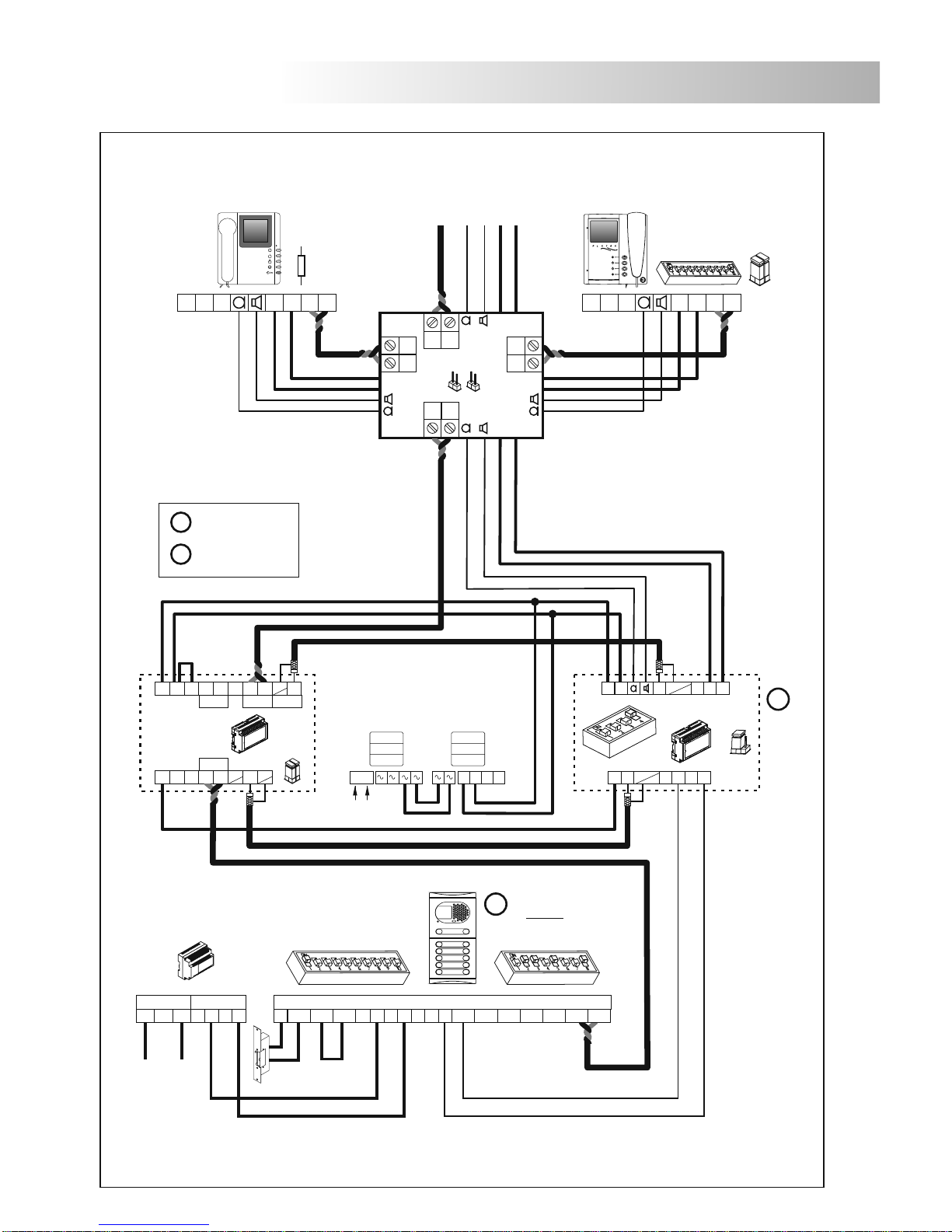
9
INSTALLATION DIAGRAMS
Replacement in a 90 system mode (video installation without coaxial cable).
+
-
230 110 0
-
+
SEC
PRI
FA- PLUS/C
ver. 938072
DAo
Ain
Vi
CT+
Vo
+
CD-PLUS/90
-
JP1
ViVo
+
-
Malla
-
Malla
-
A-490/1
N R
+
-
2
0 220
PRI
1
A-490/2
_
+
Vp
Shiner 90
SAA1 2C
100W
+
Platea 90
SAA1 2C
D2L-90/2H
+
SW1
**
*
**
Malla
Vout
CT+
EL-564
Vp2 Mp2
--
-
Malla
-
IN
JP1
Vp1
+
Vp1 Mp1
-
TP In TP Out Coax In
-
Mp1
Malla
-
Vin2C
+
Vpo Mpo
Vpi Mpi
+
Md1
Vd1
Md2
Vd2
_
_
_
Mp
_
VpMp
+
_
TP to Coax
Coax to TP
EL562
JP1
JP1 JP2
SW2 SW1
D
Malla
Vin-AinAout Vin+ Vout-Vout+
CN2
+AP
- -
+
CV1CV2-+12
-
EL500SE
PLUS BUS
90 BUS
M
M
Plus door panel
Main
IMPORTANT: To configure and to program each equipment see the appropiate instruction book.
For other configurations of replacement contact with your distributor.
M =Master.
S =Slave.
**
Configuring the end of
line in the last monitor.
Remove the jumpers JP1 &
JP2 in all distributors except
in the last one.
*
Next
Distributor
Page 10
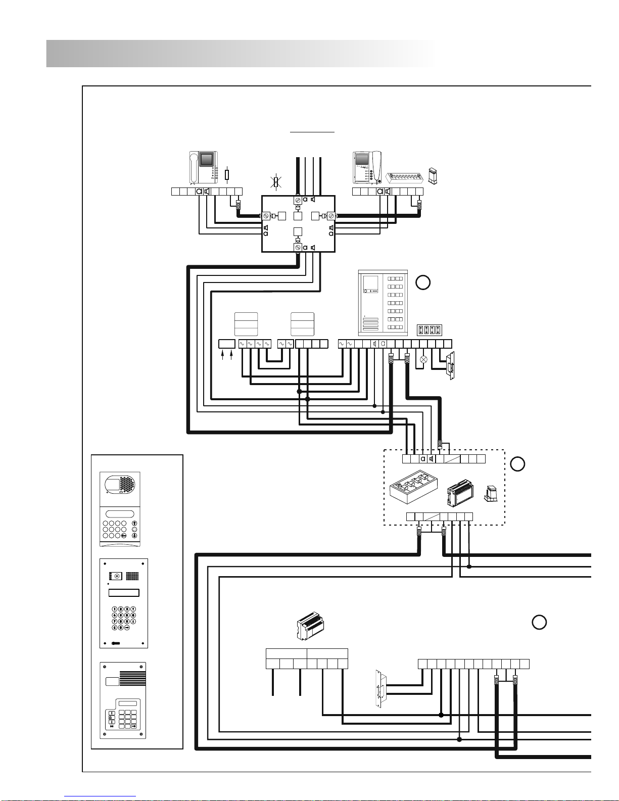
10
INSTALLATION DIAGRAMS
V
out-Vout+
MALLA
V
in+Vin-Ain
A
out
D
+
-
CV+CV
-
General door panel
Communication R. : ACTIVATED
1
4
7
2
5
8
3
6 0
9
C
1
4
7
2
5
8
0
C
ANCEL
O.K.
3
6
9
(1)
General door panel
STADIO
INOX
ROCK
FA-PLUS/C
rev.938072
+
-
230 110 0
-
+
SEC
PRI
Main
(1)
BACKBONE 1
IMPORTANT: To configure and to program each equipment see the appropiate instruction book.
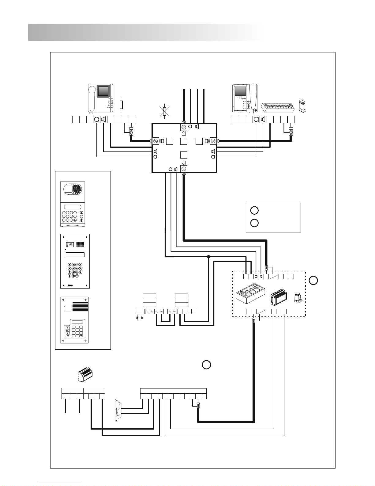
ackbone encoder mode (Plus general door panels with coaxial cable).
B
M
DAo
Ain
Vi
CT+
Vo
+
CD-PLUS/90
PLUS BUS
90 BUS
-
JP1
M
ViVo
+
-
Malla
-
Malla
-
CV
1 Vout Vin
L1
L2 CV CV
A
2
+
-
-
1 2 3SW4
PV-90
A-490/1
N R
+
-
2
0 220
PRI
1
A-490/2
S
Next
Distributor
_
+
V
in
V
out
Shiner 90
SAA12C
75W
_
+
V
in
V
out
Platea 90
SAA12C
D2L-90
E
S
75W
D1 D2
+
+
+
SW1
**
*
**
+
CN4
Page 11
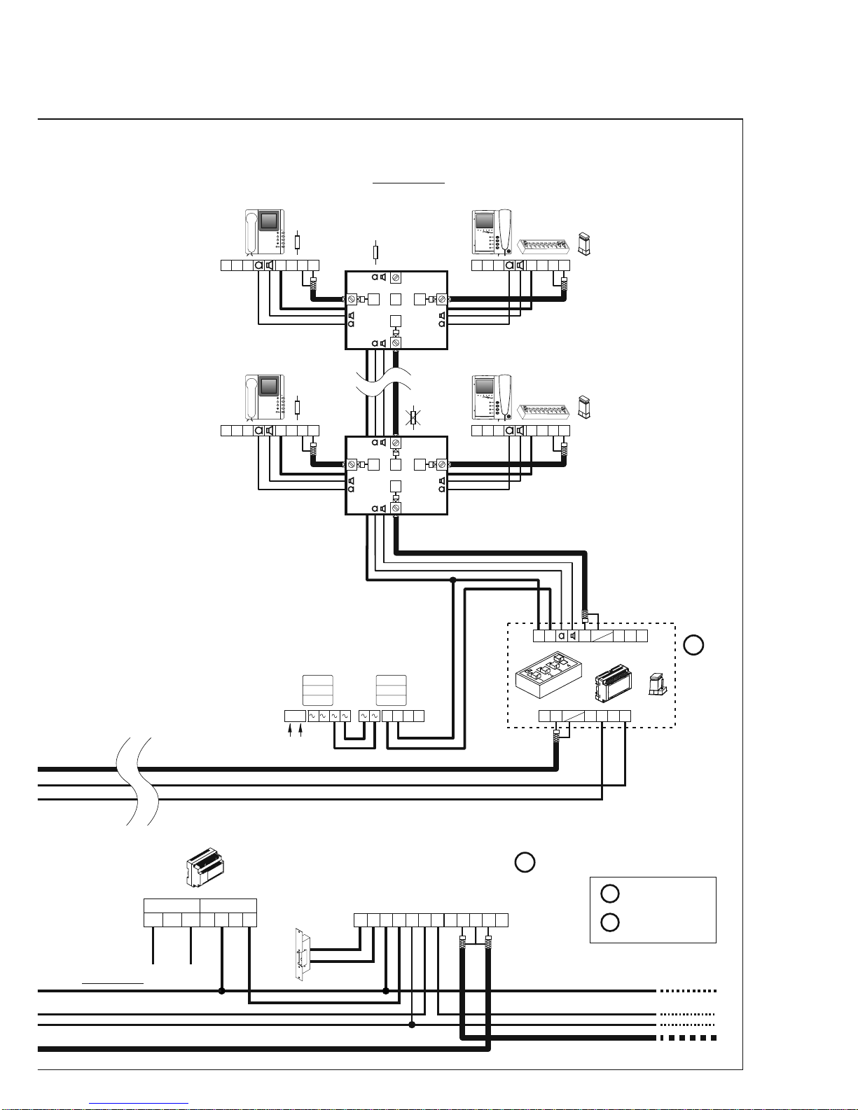
11
To the next
door panel/s
V
out-Vout+
MALLA
V
in+Vin-Ain
A
out
D
+
-
CV+CV
-
General door panel
Communication R. : DEACTIVATED
FA-PLUS/C
rev.938072
+
-
230 110 0
-
+
SEC
PRI
Main
(1)
S
DAo
Ain
Vi
CT+
Vo
+
CD-PLUS/90
PLUS BUS
90 BUS
-
JP1
M
ViVo
+
-
Malla
-
Malla
-
A-490/1
N R
+
-
2
0 220
PRI
1
A-490/2
_
+
V
in
V
out
Shiner 90
SAA12C
75W
_
+
V
in
V
out
Platea 90
SAA12C
D2L-90
E
S
75W
D1 D2
+
+
+
SW1
**
*
**
BACKBONE 250
M =Master.
S =Slave.
**
Configuring the end of
line in the last monitor.
distributors except in
the last one.
Cut the resistor in all
*
_
+
V
in
V
out
Shiner 90
SAA12C
75W
_
+
V
in
V
out
Platea 90
SAA12C
D2L-90
E
S
D1 D2
+
+
+
SW1
**
*
**
75W
+
+
CN4
CN4
BACKBONE 0
Page 12
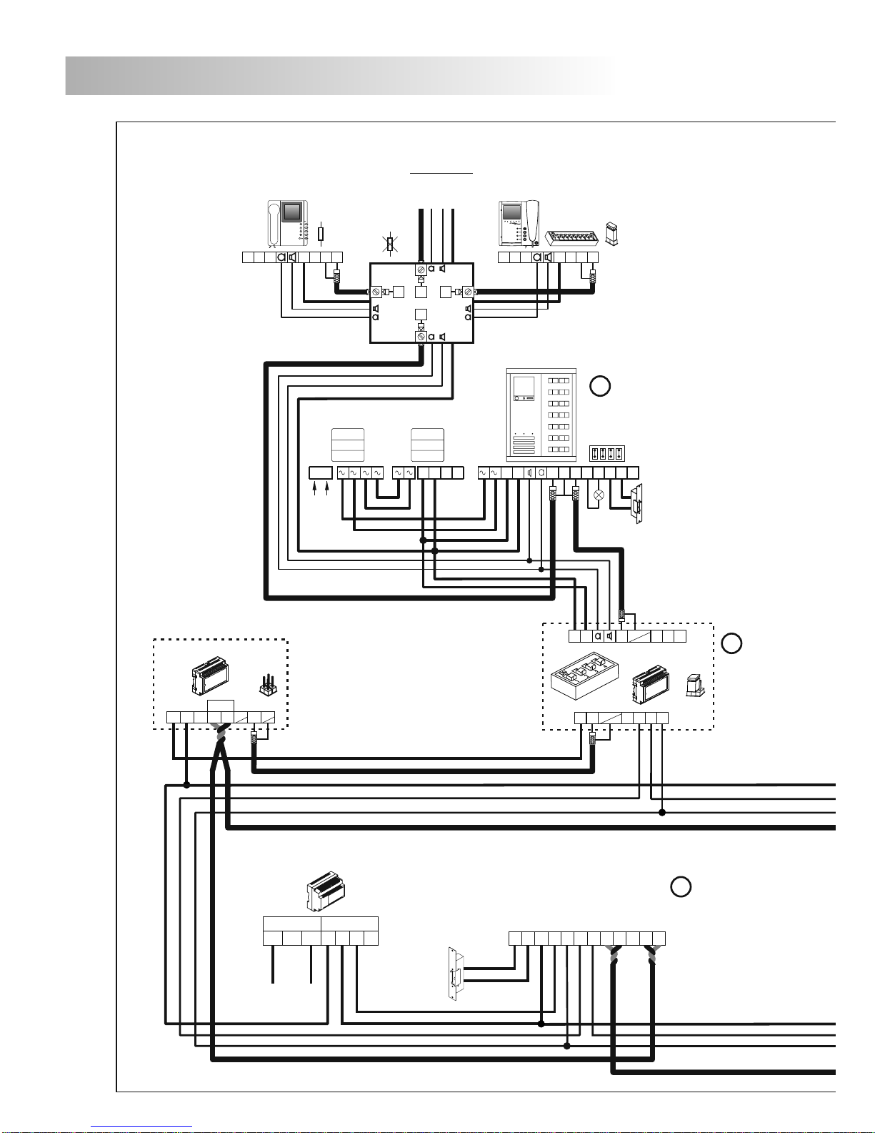
12
INSTALLATION DIAGRAMS
V
out-Vout+
MALLA
V
in+Vin-Ain
A
out
D
+
-
CV+CV
-
General door panel
Communication R. : ACTIVATED
FA-PLUS/C
rev.938072
+
-
230 110 0
-
+
SEC
PRI
Main
IMPORTANT: To configure and to program each equipment see the appropiate instruction book.
M
BACKBONE 1
M
CV
1 Vout Vin
L1
L2 CV CV
A
2
+
-
-
1 2 3SW4
PV-90
A-490/1
N R
+
-
2
0 220
PRI
1
A-490/2
DAo
Ain
Vi
CT+
Vo
+
CD-PLUS/90
PLUS BUS
90 BUS
-
JP1
ViVo
+
-
Malla
-
Malla
-
S
Next
Distributor
_
+
V
in
V
out
Shiner 90
SAA12C
75W
_
+
V
in
V
out
Platea 90
SAA12C
D2L-90
E
S
75W
D1 D2
+
+
+
SW1
**
*
**
+
ackbone encoder mode (general door panels without coaxial cable).
B
Malla
Vout
CT+
EL-564
Vp2 Mp2
--
-
Malla
-
IN
JP1
CN4
Page 13
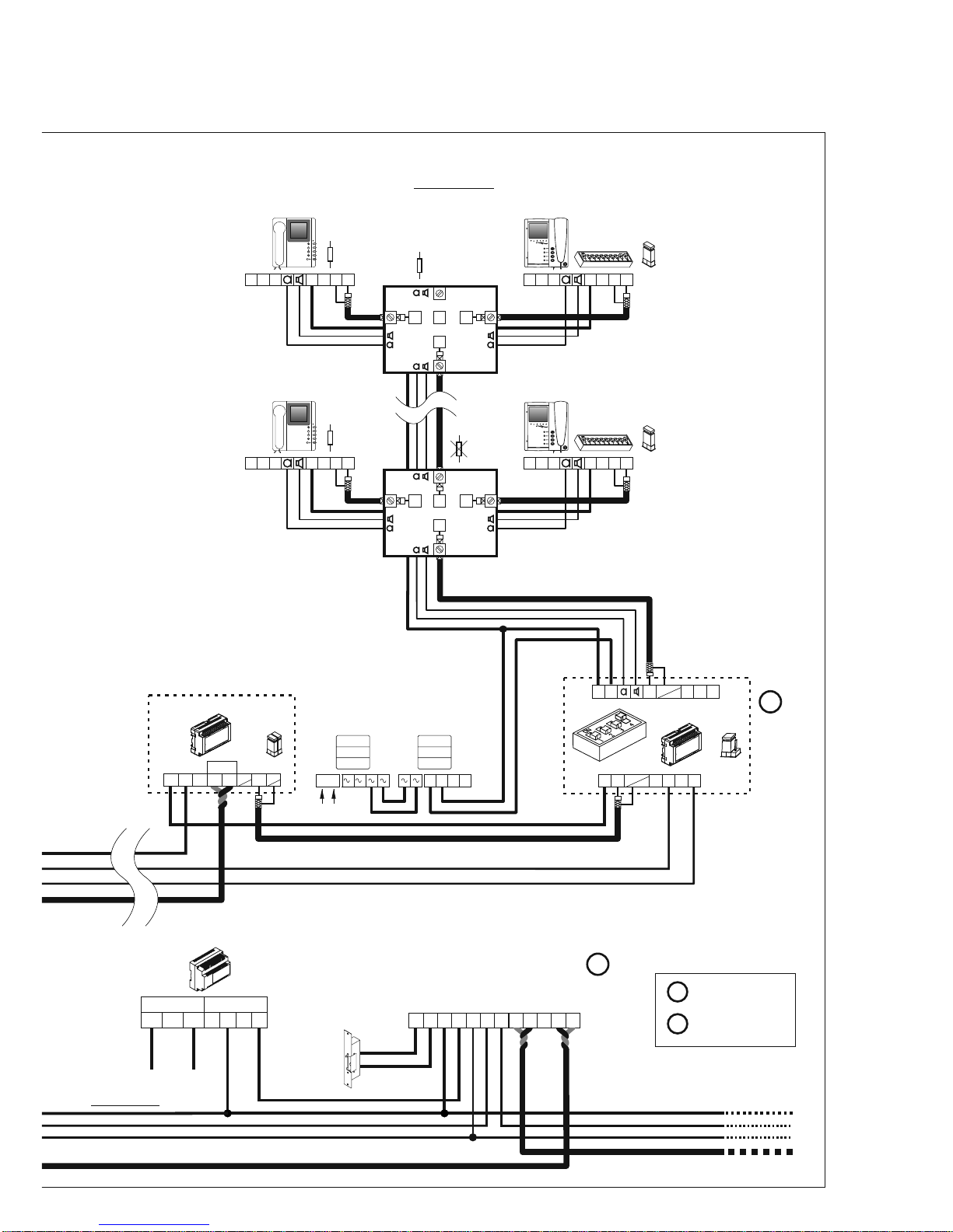
13
V
out-Vout+
MALLA
V
in+Vin-Ain
A
out
D
+
-
CV+CV
-
General door panel
Communication R.: DEACTIVATED
FA-PLUS/C
rev.938072
+
-
230 110 0
-
+
SEC
PRI
Main
S
_
+
V
in
V
out
Shiner 90
SAA12C
75W
_
+
V
in
V
out
Platea 90
SAA12C
D2L-90
E
S
75W
D1 D2
+
+
+
SW1
**
*
**
BACKBONE 250
Malla
Vout
CT+
EL-564
Vp2 Mp2
--
-
Malla
-
IN
JP1
DAo
Ain
Vi
CT+
Vo
+
CD-PLUS/90
PLUS BUS
90 BUS
-
JP1
M
ViVo
+
-
Malla
-
Malla
-
A-490/1
N R
+
-
2
0 220
PRI
1
A-490/2
_
+
V
in
V
out
Shiner 90
SAA12C
75W
_
+
V
in
V
out
Platea 90
SAA12C
D2L-90
E
S
D1 D2
+
+
+
SW1
**
*
**
75W
+
+
M =Master.
S =Slave.
**
Configuring the end of
line in the last monitor.
distributors except in
the last one.
Cut the resistor in all
*
CN4
CN4
BACKBONE 0
To the next
door panel/s
Page 14
14
INSTALLATION DIAGRAMS
IMPORTANT: To configure and to program each equipment see the appropiate instruction book.
V
out-Vout+
MALLA
V
in+Vin-Ain
A
out
D
+
-
CV+CV
-
+
-
230 110 0
-
+
SEC
PRI
Main
FA- PLUS/C
ver. 938072
DAo
Ain
Vi
CT+
Vo
+
CD-PLUS/90
PLUS BUS
90 BUS
-
JP1
M =Master.
S =Slave.
M
ViVo
+
-
Malla
-
Malla
-
A-490/1
N R
+
-
2
0 220
PRI
1
A-490/2
Next
Distributor
_
+
V
in
V
out
Shiner 90
SAA1 2C
75W
_
+
V
in
V
out
Platea 90
SAA1 2C
D2L-90
E
S
75W
D1 D2
+
+
+
+
CN1
SW1
**
Configuring the end of
line in the last monitor.
**
distributors except in
the last one.
Cut the resistor in all
*
*
**
For other configurations of replacement contact with your distributor.
1
4
7
2
5
8
3
6 0
9
C
1
4
7
2
5
8
0
C
ANCEL
O.K.
3
6
9
(1)
Coded panel
STADIO
INOX
ROCK
Coded panel
Communication R. : ACTIVATED
M
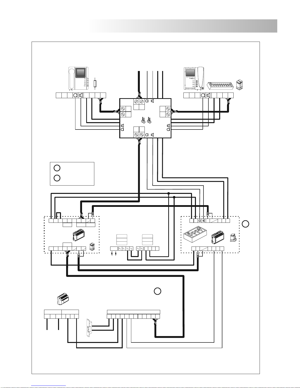
ackbone encoder mode (Coded panel and installation with coaxial cable.)
B
(1)
CN4
Page 15
15
INSTALLATION DIAGRAMS
IMPORTANT: To configure and to program each equipment see the appropiate instruction book.
V
out-Vout+
MALLA
V
in+Vin-Ain
A
out
D
+
-
CV+CV
-
+
-
230 110 0
-
+
SEC
PRI
Main
FA- PLUS/C
ver. 938072
DAo
Ain
Vi
CT+
Vo
+
CD-PLUS/90
PLUS BUS
90 BUS
-
JP1
M =Master.
S =Slave.
M
ViVo
+
-
Malla
-
Malla
-
A-490/1
N R
+
-
2
0 220
PRI
1
A-490/2
Next
Distributor
_
+
Vp
Shiner 90
SAA1 2C
100W
+
Platea 90
SAA1 2C
D2L-90/2H
+
CN1
SW1
**
Configuring the end of
line in the last monitor.
**
Remove the jumpers JP1 &
JP2 in all distributors except
in the last one.
*
*
**
For other configurations of replacement contact with your distributor.
Coded panel
Communication R. : ACTIVATED
M
ackbone encoder mode (Coded panel and installation without coaxial cable).
B
(1)
Malla
Vout
CT+
EL-564
Vp2 Mp2
--
-
Malla
-
IN
JP1
Vp1
+
Vp1 Mp1
-
TP In TP Out Coax In
-
Mp1
Malla
-
Vin2C
+
Vpo Mpo
Vpi Mpi
+
Md1
Vd1
Md2
Vd2
_
_
_
Mp
_
VpMp
+
_
TP to Coax
Coax to TP
EL562
JP1
JP1 JP2
Page 16

16
TROUBLESHOOTING HINTS
Replacement 90 door panel mode
OCalls cannot be made.
w Remember that the system remains inactive for 45 seconds after connecting the power supply.
w Ensure that the backbone for the replacement Plus door panel is configured with address "0".
(The converter is factory set with backbone address "0").
w Check the connection of the converter (page 38 to 40) and its configuration (page 36).
w Check the 90 monitor of the installation with address "0" has been configured with another
free address (see page 36).
Backbone encoder mode (General door panels)
O Calls cannot be made from the general door panels.
w Remember that the system remains inactive for 45 seconds after connecting the power supply.
w Check if calls can be made from the inner door panels (if these exist).
w Ensure that the backbone for the converters has been correctly programmed (page 37) and
check their connection (pages 41 to 44) and their configuration (page 36).
w Check the configuration and codification (address) of the monitors (see page 36 and
).
w Check that the voltage between "+" and "-" terminals of the A-490/2 power supply, is 24 Vdc.,
if this is not the case, disconnect the power supply from the installation and measure again.
If it's correct now, it means there is a short circuit in the installation. Disconnect the power
supply from mains and check the installation.
w Check that the voltage between "+" and "-" terminals of the converter and the different
elements of the 90 installation is 24Vd.c, if this is not the case, check the power supply and
its connections.
w Check that the voltage between "+" and "-" terminals of the FA-Plus/C power supply is from
17,5 to 18,5Vd.c., if not, check the power supply and its connections.
OThe converter cannot be programmed.
w Check that the general coded panel is in configuration mode before setting the number 1 dip
switch to ON (see page 36) and the programming steps are correctly followed (page 33).
w Check autodiagnostic leds (see page 37).
w Check that the voltage between "+" and "-" terminals of the converter is 24 Vdc., if not, check
the power supply and its connections.
Backbone encoder mode (Coded panel)
O Calls cannot be made.
w Remember that the system remains inactive for 45 seconds after connecting the power supply.
w Ensure that the backbone for the replacement Plus coded panel is configured with address
"0".
(The converter is factory set with backbone address "0".).
w Check the converter's connection (page 45-46) and their configuration (page 36).
w Check the configuration and codification (address) of the monitors (see page 36 and
).
w Check that the voltage between "+" and "-" terminals of the A-490/2 power supply, is 24 Vdc.,
if this is not the case, disconnect the power supply from the installation and measure again.
If it's correct now, it means there is a short circuit in the installation. Disconnect the power
supply from mains and check the installation.
w Check that the voltage between "+" and "-" terminals of the converter and the different
elements of the 90 installation is 24Vd.c, if this is not the case, check the power supply and
its connections.
w Check that the voltage between "+" and "-" terminals of the FA-Plus/C power supply is from
17,5 to 18,5Vd.c., if not, check the power supply and its connections.
the
appropiate instruction book
the
appropiate instruction book
Page 17
1095 Budapest, Mester utca 34.
Tel.: *218-5542, 215-9771, 215-7550,
216-7017, 216-7018 Fax: 218-5542
Mobil: 30 940-1970, 30 959-0930
E-mail: [email protected] Web: www.delton.hu
www.golmar.hu
1141 Budapest, Fogarasi út 77.
Tel.: *220-7940, 220-7814, 220-7959,
220-8881, 364-3428 Fax: 220-7940
Mobil: 30 531-5454, 30 939-9989
 Loading...