

IMPORTANT SAFETY INFORMATION
This symbol is to alert you to important operating
or servicing instructions that appear in your
instructions. Always follow basic safety
precautions when using this product to reduce
the risk of injury, fire or electric shock.
TEN YEAR LIMITED WARRANTY
Golight, Inc. warrants the GXL
that are due to workmanship for parts or faulty materials, for
ten years from date of original purchase. This warranty to the
GXL® does not cover damage resulting from unreasonable use
or misuse, unreasonable maintenance or loss, or labor costs.
®
against any deemed defects
®
This light is for off road and utility use only. It is not
designed for road use as a driving light.
Warranty information may be filled out online at:
www.golight.com/products/registration.html
®
If the GXL
specification, send the light, and all necessary accessories
postage paid, plus $9.95 for shipping and handling to Golight,
Inc., Service Department, 37146 Old Hwy 17, Culbertson, NE
69024. No C.O.D.’s accepted. Only the above manufacturer is
authorized to perform warranty repair or replace product.
Any consequential damages to person or property are excluded
from this warranty. Some states do not allow the exclusion
and limitation of incidental or consequential damages, therefore, the above limitations or exclusions may not apply to you.
This warranty gives you specific legal rights and you may also
have other rights.
does fail to operate under warranted
Golight Inc
37146 Old Hwy 17
Culbertson, NE 69024
800.557.0098 | 308.278.3131
www.golight.com | info@golight.com
Instruction Guide
Congratulations
You are now the owner of one of the finest lighting products
available today. Thank you for letting Golight® assist you in
your lighting application needs.
We’re proud of our products and the technology that we’ve
developed to ensure our customers the most durable,
versatile and powerful lights in the industry.
Please read these
instructions before
using your new
Golight® GXL®.
The GXL® is an LED, fixed-mount work light offering incredible
intensity and durability in a small package. Utilizing the latest in
LED, lens and reflective technology, the GXL® casts light where
you need it.
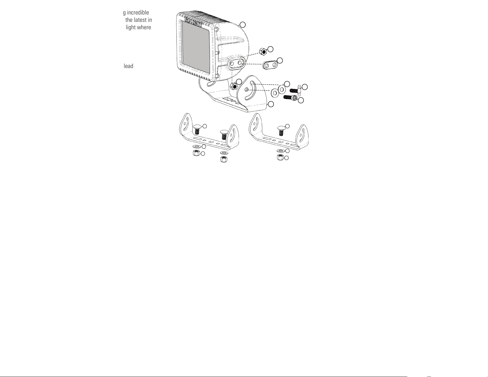
Contents:
Bracket to mounting surface hardware:
1. Qty. 1: GXL® light head with 3ft., 2 wire power lead
2. Qty. 1: Mounting bracket
3. Qty. 2: 3/8” x 1 ¼” carriage bolts
4. Qty. 2: Large flat washers
5. Qty. 2: 3/8 in. lock nuts
Bracket attachment hardware:
6. Qty. 2: Spacers
7. Qty. 4: 1/4” x 1 1/8” socket head cap screws (allen screws)
8. Qty. 4: Locknuts
9. Qty. 4: Small flat washers
10. Qty. 2: Thumb Screws (optional)
Mounting / Installation:
1. Determine a suitable mounting location for the light.
2. Once a location has been decided upon, use the mounting
bracket as a template to mark appropriate bolt-hole locations—
note that the vertical adjustment channel on the bracket indicates
the posterior side of the bracket/light(refer to diagram).
3. The GXL® can be mounted using one or both of the provided
carriage bolts. If future adjustment along the horizontal access is
desired, the light should be affixed using one bolt inserted through
the center mounting hole. If the light is to remain static along the
horizontal axis, both bolts should be used to affix the light and
should utilize the holes nearest the vertical arm on the either side
of the mounting bracket.
1
8
6
8
3 3
4
5
or
9
10
2
7
4
5
4. Drill mounting holes using a 7/16” drill bit.
**Before attaching the mounting bracket to the surface, attach
the mounting bracket to the GXL® :
5. When attaching the mounting bracket to the GXL® , the
included oval spacers must be installed between the bracket
and GXL® to ensure a proper fit.
6. After inserting the spacers into their receptacle on the right
and left lateral of the GXL® (refer to diagram) the arms of the
mounting bracket can be positioned over the spacers with the
pivot hole and vertical channel aligned with the corresponding
attachment holes.
7. The mounting bracket should be affixed using the allen screws
and lock nuts provided. Slide the inward facing lock nuts into the
channels molded into the heat sink on the back of the light. The
channels are molded in such a manner that no tool is required
to hold the nut in place while tightening. The included thumb
screws may be utilized in place of the socket head cap screws
in the vertical channel to facilitate easier vertical adjustment.
Installation of the thumb screw should follow the same procedure
as the socket head cap screw. Take care not to over tighten the
associated hardware in the pivot hole.
8. Insert the allen screws through the holes and thread them into
their corresponding nut.
9. After attaching the mounting bracket to the GXL® align the
bracket with the pre-drilled hole/holes and affix the unit with the
supplied carriage bolt/bolts.
10. Adjust GXL® to desired position and tighten all hardware.
Wiring Procedure and Power Requirements:
1. Extend the red (+) wire to a customer supplied on/off switch
2. Extend another wire from the on/off switch to the positive (+)
terminal of the vehicle battery. Installation of an in-line 7-10 amp
fuse is recommended.
3. Extend the black (-) wire to the negative (-) terminal of the
vehicle battery or to a solid chasis ground.
4. Please take note that appropriately sized (awg) must be
installed according to the length of wire and the necessary
capacity. The GXL will draw 5.5 amps (nominal) at 12V DC and
2.5 amps (nominal) at 24V DC. The GXL® will accept voltage
between 9V-36V DC.
 Loading...