

Page 1
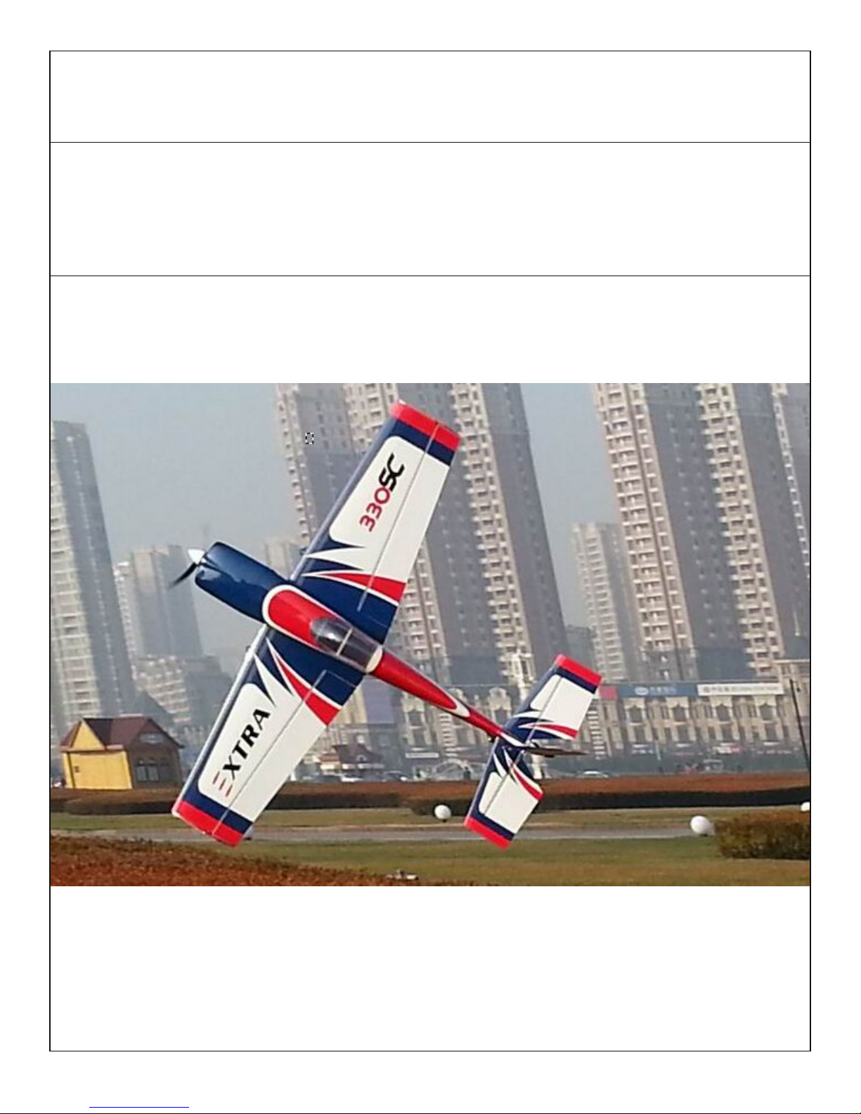
GOLDWING RC
73in EXTRA330SC 120E & 30CC
Giant Scale Aerobatic Aircraft
Page 2

Specifications
Wing Span: 73"(1860mm)
Length: 70"(1780mm)
Wing Area: 10287sq in(66.3sq dm)
Flying Weight: Gas Version is 9.7-10.5lbs(4400-4700g)
Electric Version is 9-10lbs(4100-4500g)
Glow: .91-1.20(2C
)
1.10-1.40(4C
)
Gas
:
26CC-38CC Gas DLE30 DLE35
Electric Power:1900-2200Watt electric motor
ESC
:
80-100A
Radio: 4+ Channels
Servos: 4-5 servos required 95 oz to 160 oz (6-10kg/cm)
All contents copyright 2015, GoldWing RC
Version 2.0, June 2015
Dear Customer,
Thank you for purchasing the new Goldwing RC giant scale aerobatic aircraft. This manual covers the
EXTRA330SC 120E and 30CC aircraft. Goldwing RC proudly presents 73in EXTRA 120E & 30CC, Extreme
Series, which is a premium product line of electric & gas RC airplanes designed for unlimited 3D performance.
The new 73in EXTRA 120E & 30CC adopts cutting edge aerodynamic features, such as streamlined canopy,
aileron counterbalance, removable side force generators (SFGs) .The 73in EXTRA330SC is also loaded with
high-end accessories including genuine Oracover, CF landing gear, tail wheel assembly and control horns.
KUZA brand CNC Aluminium Backplate Hollowed-out Spinner is included as bonus (limited quantities) for
120E version. And KUZA new fuel Tank Assembly is included for 30CC version.
A QUICK WORD ABOUT SAFETY AND RADIO CONTROL FLYING MODELS
With radio control aircraft, like any hobby or sport, there are certain risks. The operator of these models is
responsible for these risks. If misused or abused, you may cause serious bodily injury and/or damage to
property. With this in mind, you will want to be certain that you build your model carefully and correctly. If
you are not an experienced flier, have your work checked and ask for help in learning to fly safely. This model
aircraft is not a toy and must be operated and flown in a safe manner at all times. Always perform a pre-flight
check of the model including all control surfaces, correct function of the radio gear, structure, radio range, and
any other area relating to the safe operation of this aircraft.
Models are not insurable but operators are. You can obtain coverage through membership in the Academy of
Model Aeronautics (AMA). For an AMA information package call 1-800-435-9262, ext. 292 or visit the AMA
website at "www.modelaircraft.org". Or if you are in any other country please contact the appropriate body.
By the act of using the final assembled model, the purchaser/operator accepts all resulting
liability.
Page 3
Goldwing RC WARRANTY AND RETURN POLICY
GoldWing RC guarantees this product to be free from defects in both material and workmanship at the date of
purchase. This does not cover any parts damaged by use, misuse or modification. In no case shall liability
exceed the original cost of this kit. Because Goldwing RC has no control over the final assembly or
equipment/components used in the final assembly, no liability shall be assumed for any damage resulting from
the use of this model by the user. By the act of using the final assembled model, the user accepts all resulting
liability. If you should find any missing or damaged parts, or have any questions about this product, please
contact within 30 days of the purchase in order to be covered by our warranty. You may contact us at
Included Features:
Improved axles (the material of the axle is stainless steel )
Flat nylon hinges for better flying strength
Aluminium hub rubber wheels
Pre-hinged control surfaces
Larger aileron and elevator design. Up to 60 degrees of throw on all control surfaces for excellent 3D
aerobatic flying
Extra covering provided for small repairs and covered in genuine Ultracote / Oracover
Canopy extended into cowl
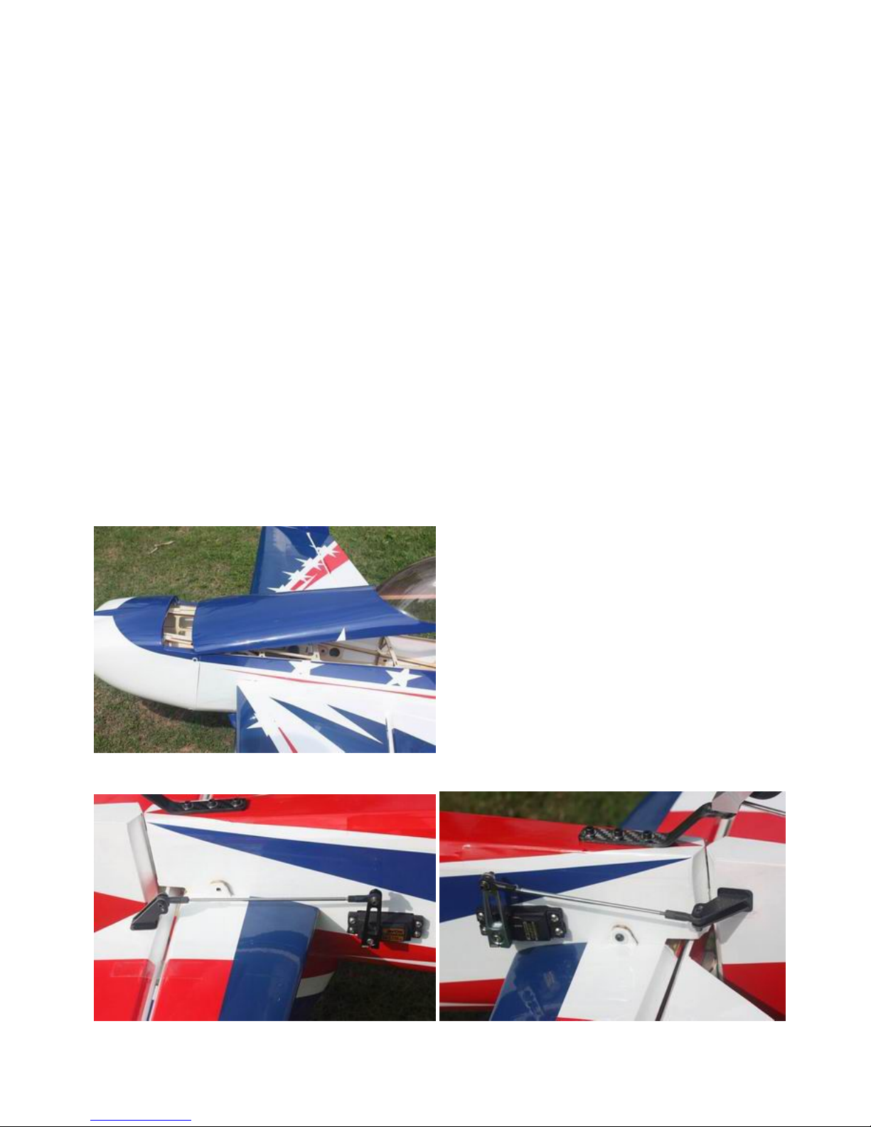
One servo for elevator. Pull-push style for rudder
X-shade wood structure ensures high strength of rudder and elevator while keeping the weight down.
Page 4
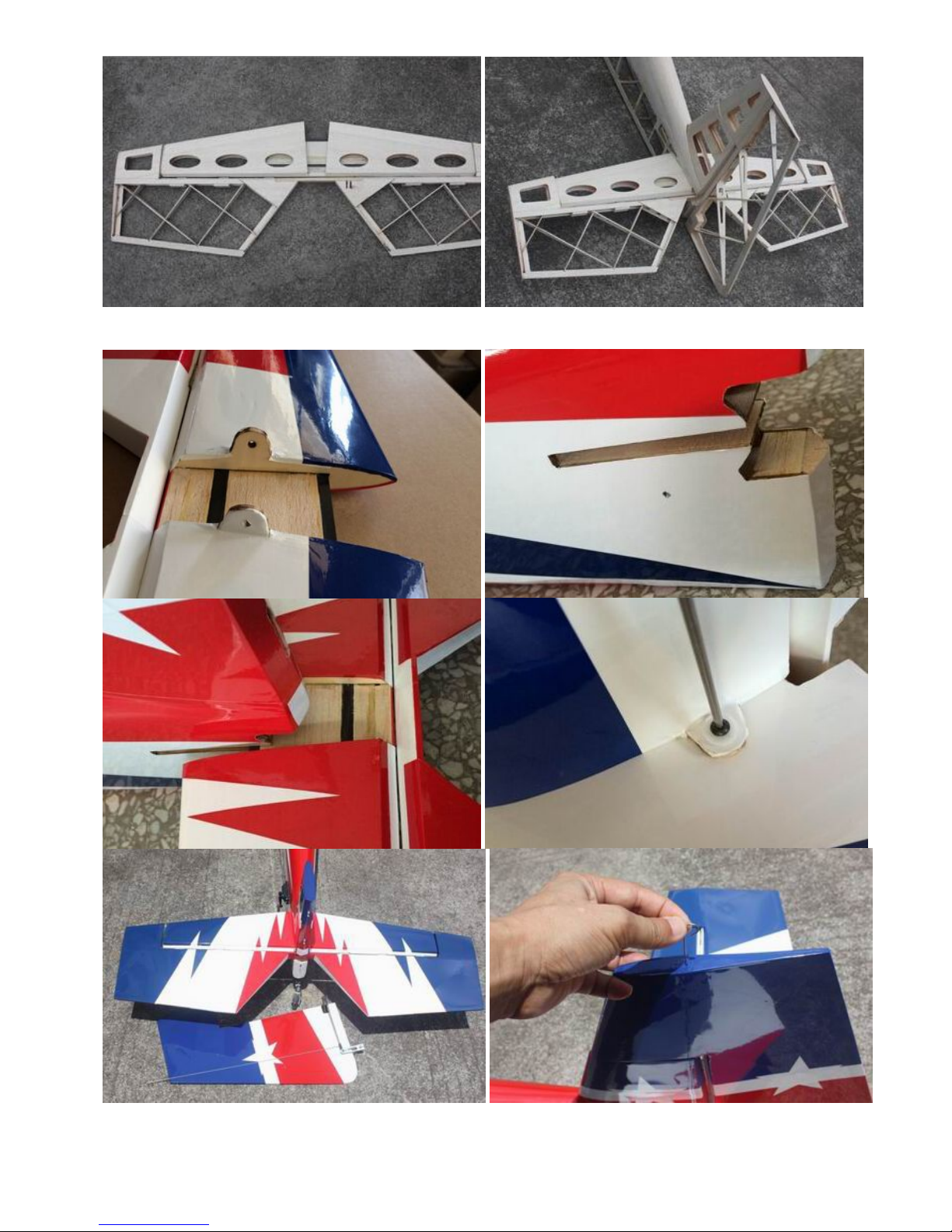
Removable stab & rudder
Page 5
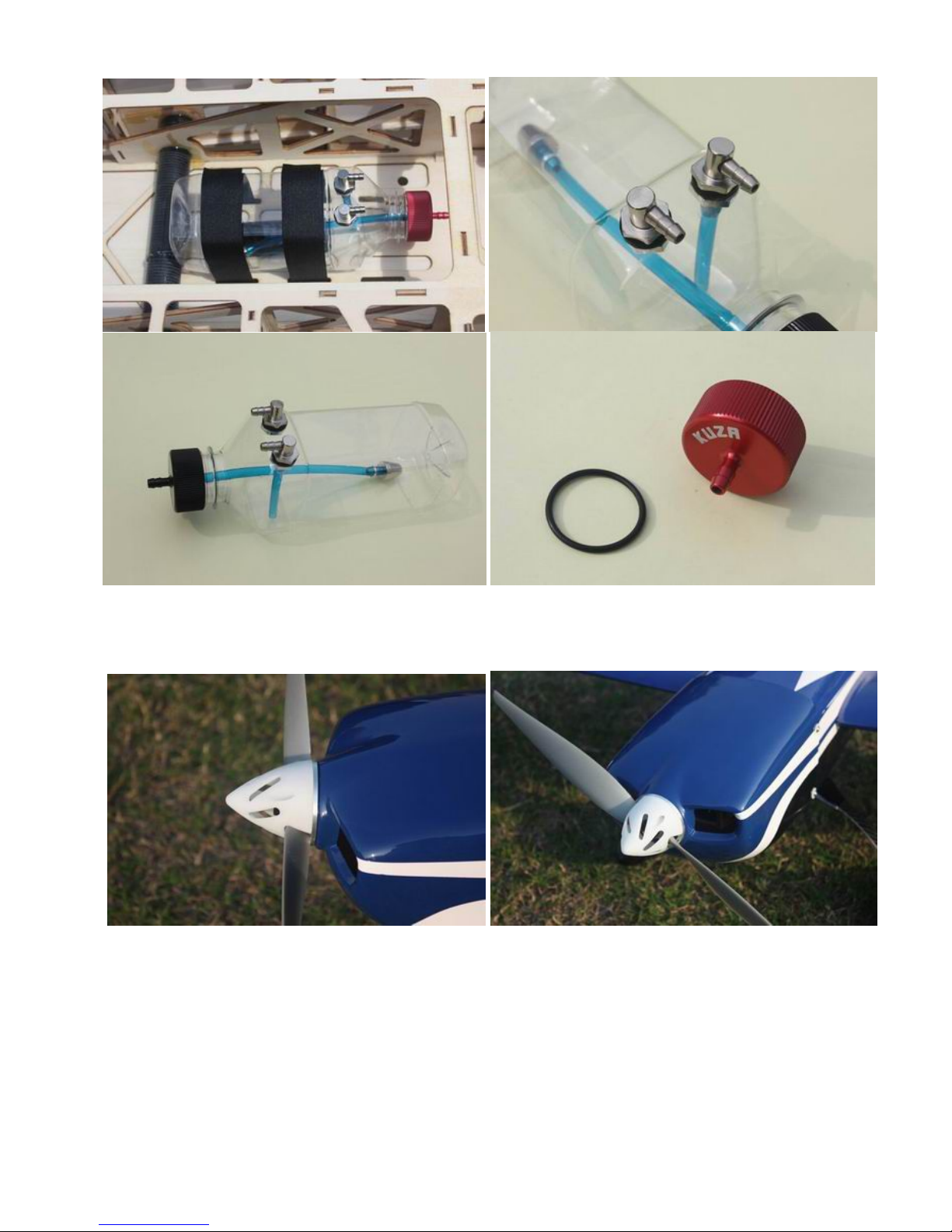
New KUZA Fuel Tank Assembly with aluminum tank cap for 30CC version
KUZA Aluminium Backplate Hollowed-out Electric Spinner included for 120E version (Excellent
cooling effect for brushless motor)
Page 6

Behind the rudder tray an air exit opening has been created for electric set-ups
Side force generators
Two latch quick release canopy.
Page 7
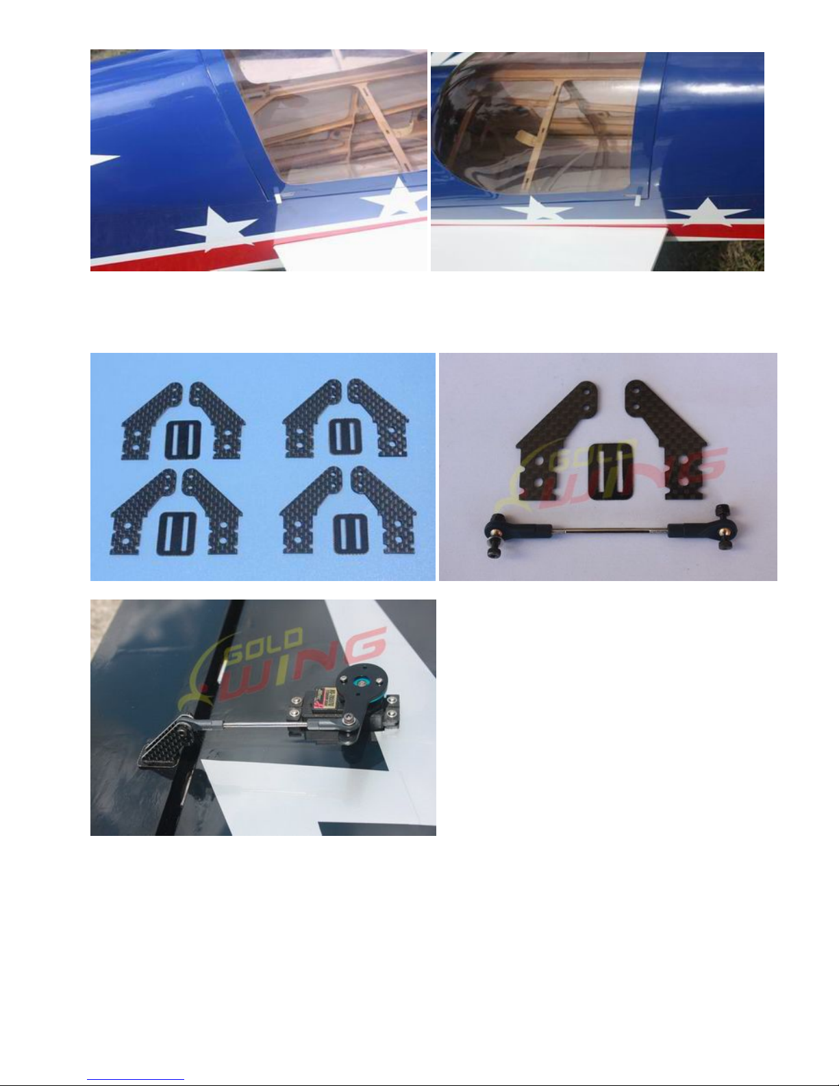
Carbon Fiber accessories version
:
Extra strength carbon fiber control horns
One piece air foiled carbon fiber landing gear
Page 8
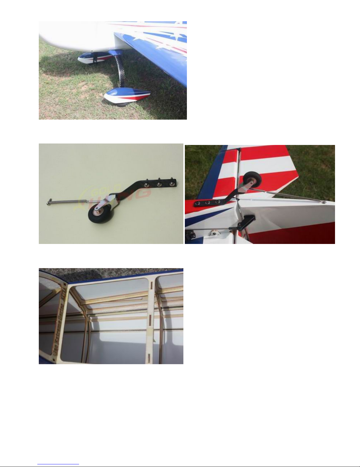
Carbon fiber tail wheel assembly with CNC machined metal parts, including the aluminium tail wheel
hub.
Strengthened fuselage by carbon fiber rods
Increased diameter carbon fiber wing tube over previous versions
Scheme B White/blue/black
Page 9
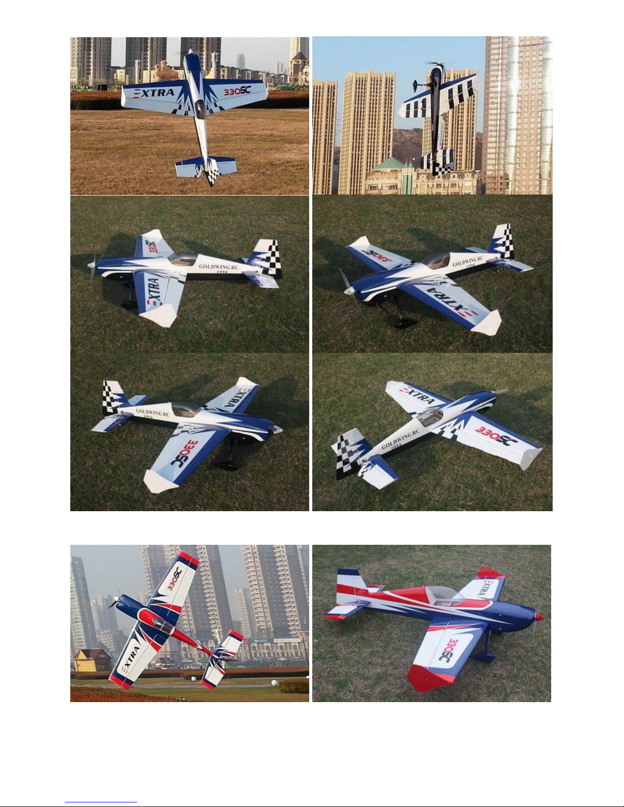
Scheme C White/blue/red
Page 10
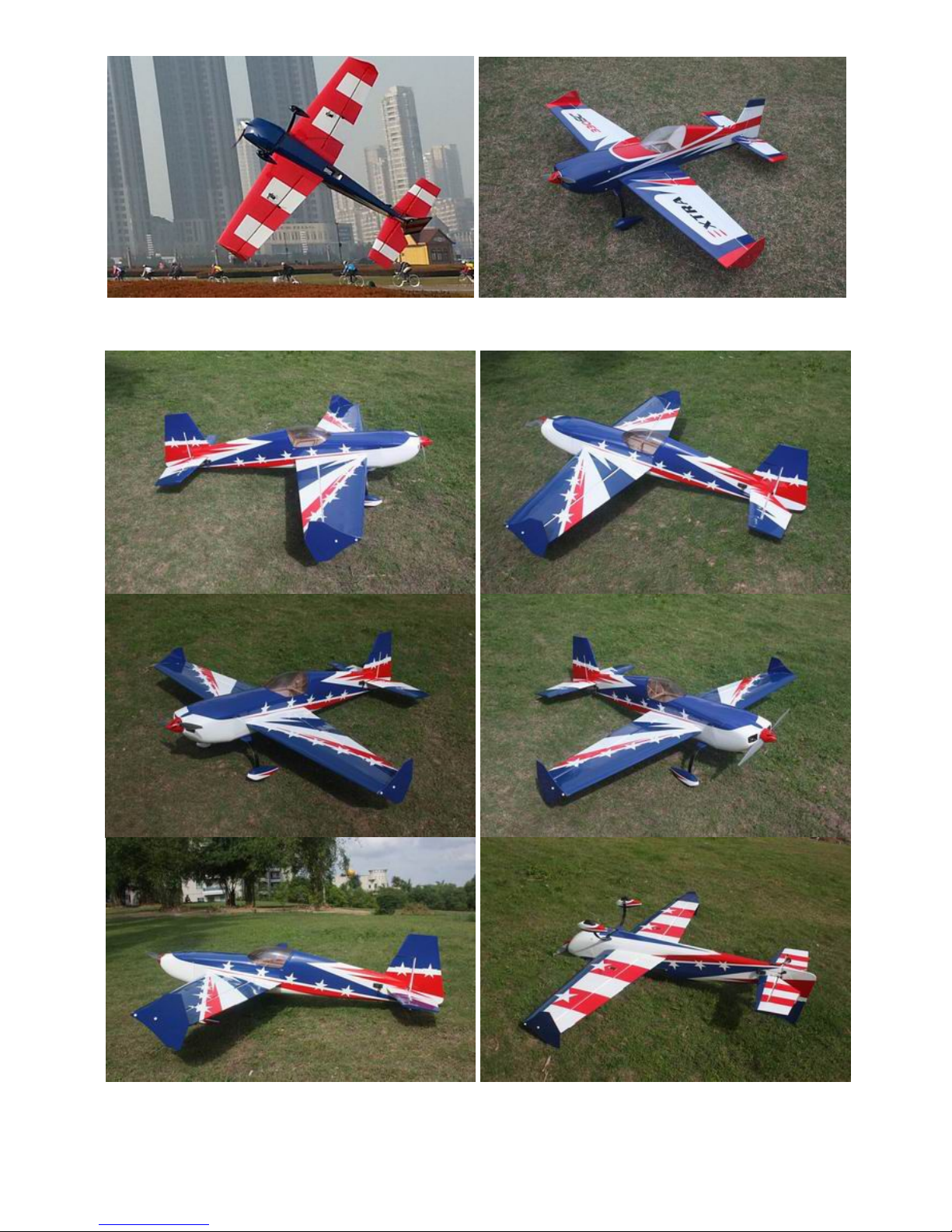
Scheme D White/blue/red
Page 11

Items required to complete this model:
26-38 cc gas engine with stock or aftermarket
exhaust system
Appropriate propeller for your engine
All the required engine and exhaust mounting
hardware
Ignition battery and switch
One quality throttle servo and appropriate servo
arm
3 high quality metal gear servos of 80 in-oz or
better for the ailerons and elevators
One high quality rudder servo of 160 in-oz or
better
Appropriate servo arms for the above
Heavy duty servo wire extensions.
Recommends three 18”, two 12” extensions.
Your installation though may vary.
Switches with charging jacks for the Rx
Rx batteries of significant capacity to power
your choice of servos.
Receiver of your choice
Required tools
Covering Iron and heat gun
Assortment normal hobby tools such as
screwdrivers, hobby knife, drill and drill bits,
pliers, etc.
Thick and thin CA adhesives
30 minute epoxy
Isopropyl alcohol
Ruler or tape measure
Blue thread-lock or equivalent
Note: As with all kits, it’s a good idea to read all the instructions and study the parts before you begin
construction. Handle the parts of this kit with care so you do not damage any of the structure or
covering. Inspect all the parts for any shipping damage and report any issues to as soon as you can.
Make sure you have a flat and sturdy workbench and follow all safety advice for the tools and adhesives
you plan to use.
AIRCRAFT COVERING
1. With all ARFs, varying temperatures and storage delays can cause covering material to loosen over time and
transportation. We recommend lightly going over all the covering with a covering iron set at medium
temperatures. Be sure to use a soft cover over your iron so you do not scratch the covering surface. Be sure
you go over all seams and edges of the covering to assure it is secure to the airframe and other covering. Be
careful not to apply too much heat or you may cause bubbles or damage to the covering. A heat gun may
also be used along with a soft cotton cloth to shrink and adhere the covering. Again, be extremely careful
when using a heat gun.
2. Be sure to seal any exposed wood with a thin coating of epoxy to prevent engine oil from soaking in. This
is especially important around the engine compartment and servo openings with exposed areas.
3. Some modelers prefer to seal the hinge gaps using strips of appropriate covering or clear trim tape. We
have found this to be helpful with models intended for higher speed flight or models with unusually large
hinge gaps. Our aircraft utilize a very tight double beveled hinge line and do not normally require this step.
Sealing the hinge gaps is therefore left as an option for the modeler.
Page 12
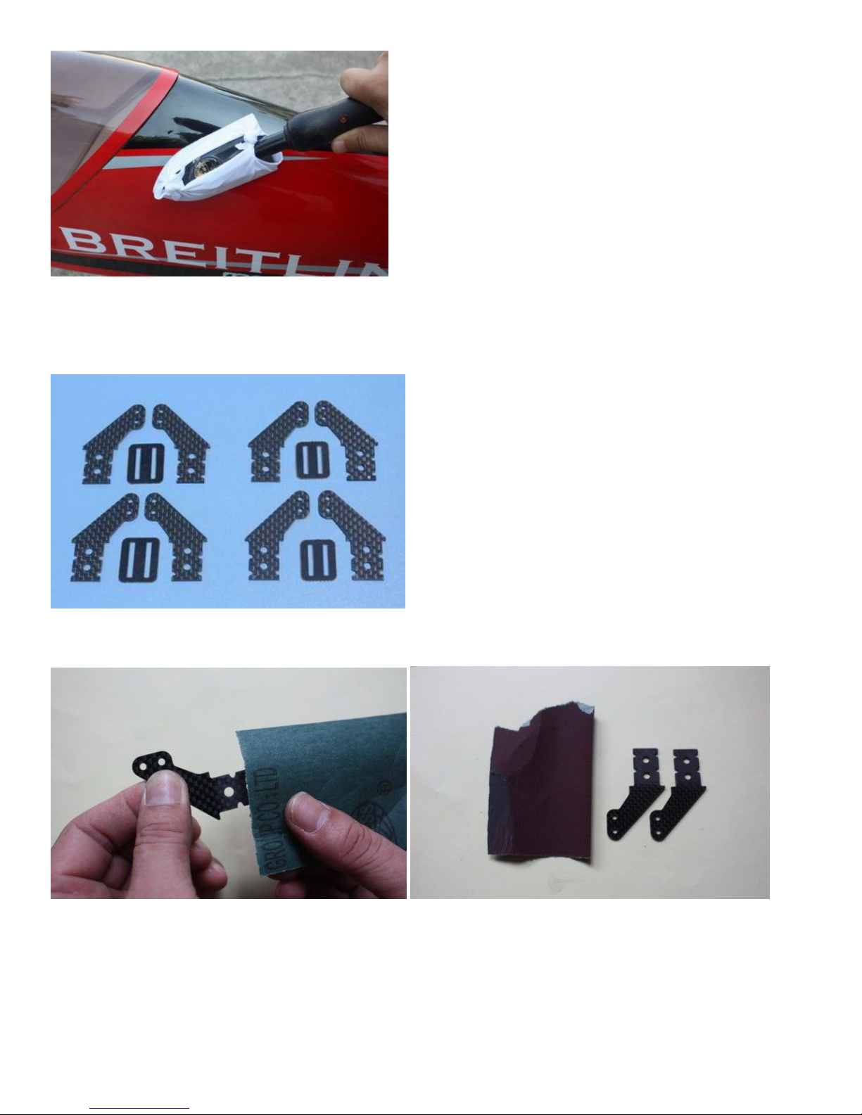
Please verify the accessories before assemble:
Carbon Fiber control Horns (Bag No. KA03CA4) : 8 single horns for ailerons and elevator and rudder.
Sand the area of the horn that will be glued to help adhesion.
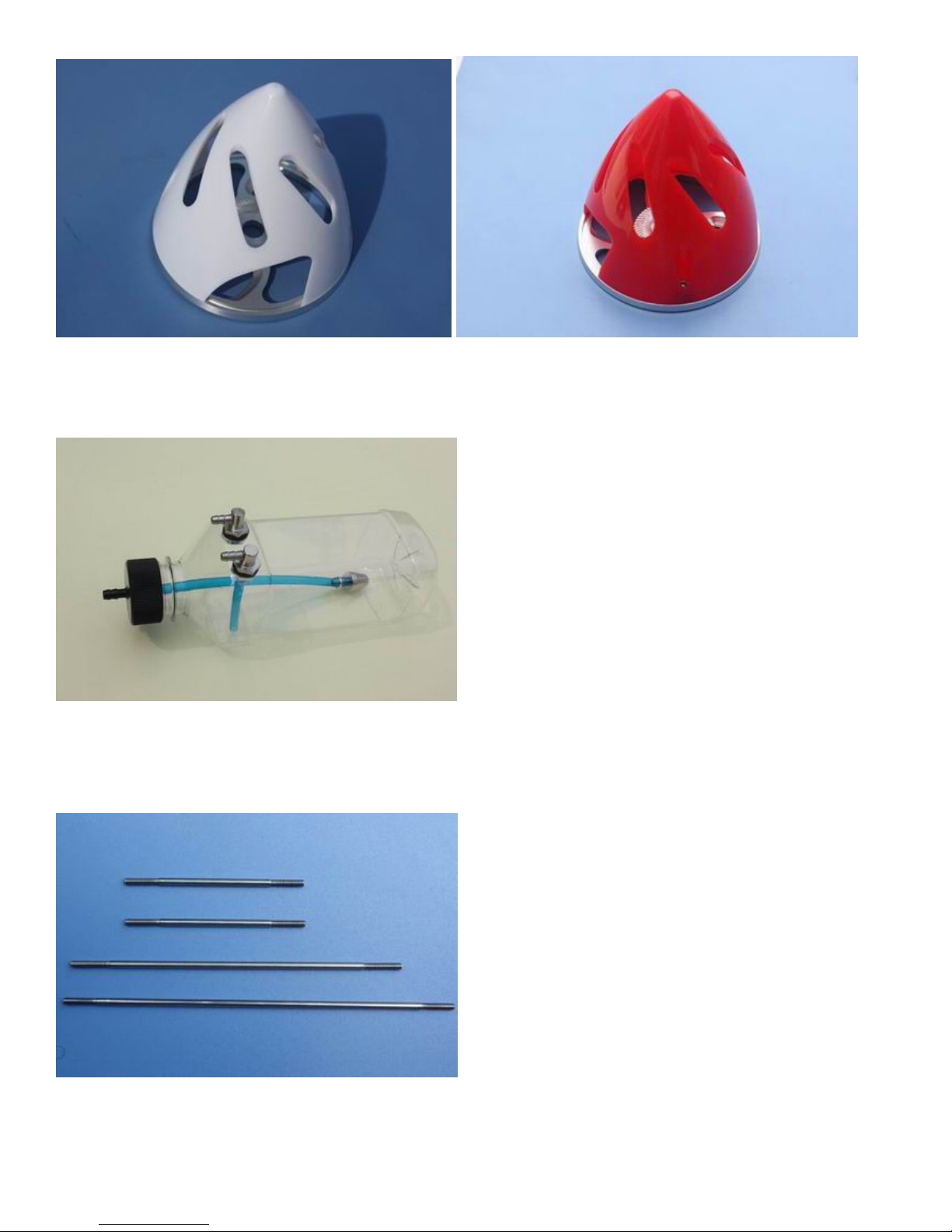
KUZA 3” Aluminium Backplate Hollowed-out Electric Spinner for 120E version (Bag No. KAG0205)
Color: Scheme B is white, Scheme C & D is red
Page 13
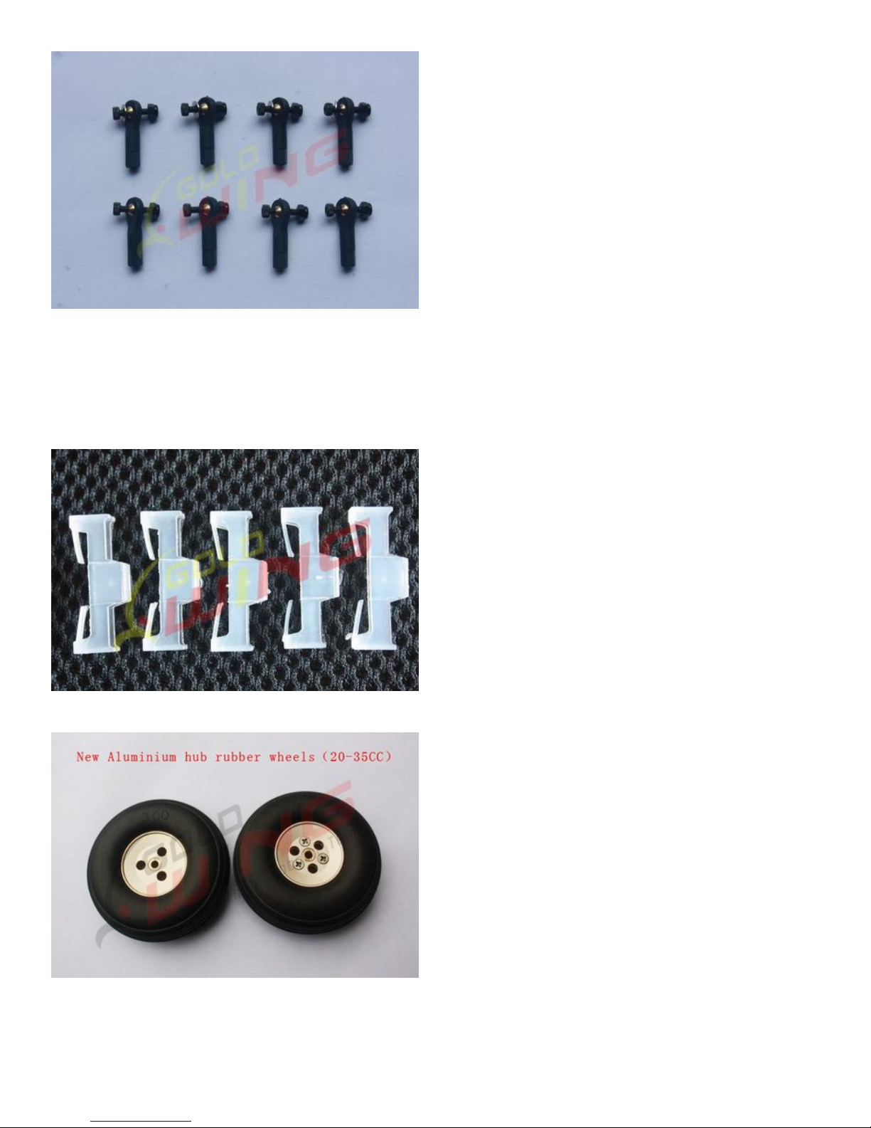
KUZA new 360cc fuel Tank Assembly for 30CC version (including Aluminum fuel cap)
Push rod kits: Two 2.5x60mm Pushrods for aileron. One 2.5x130mm Pushrod for elevator.One
2.5x110mm for rudder(Pull-push style)
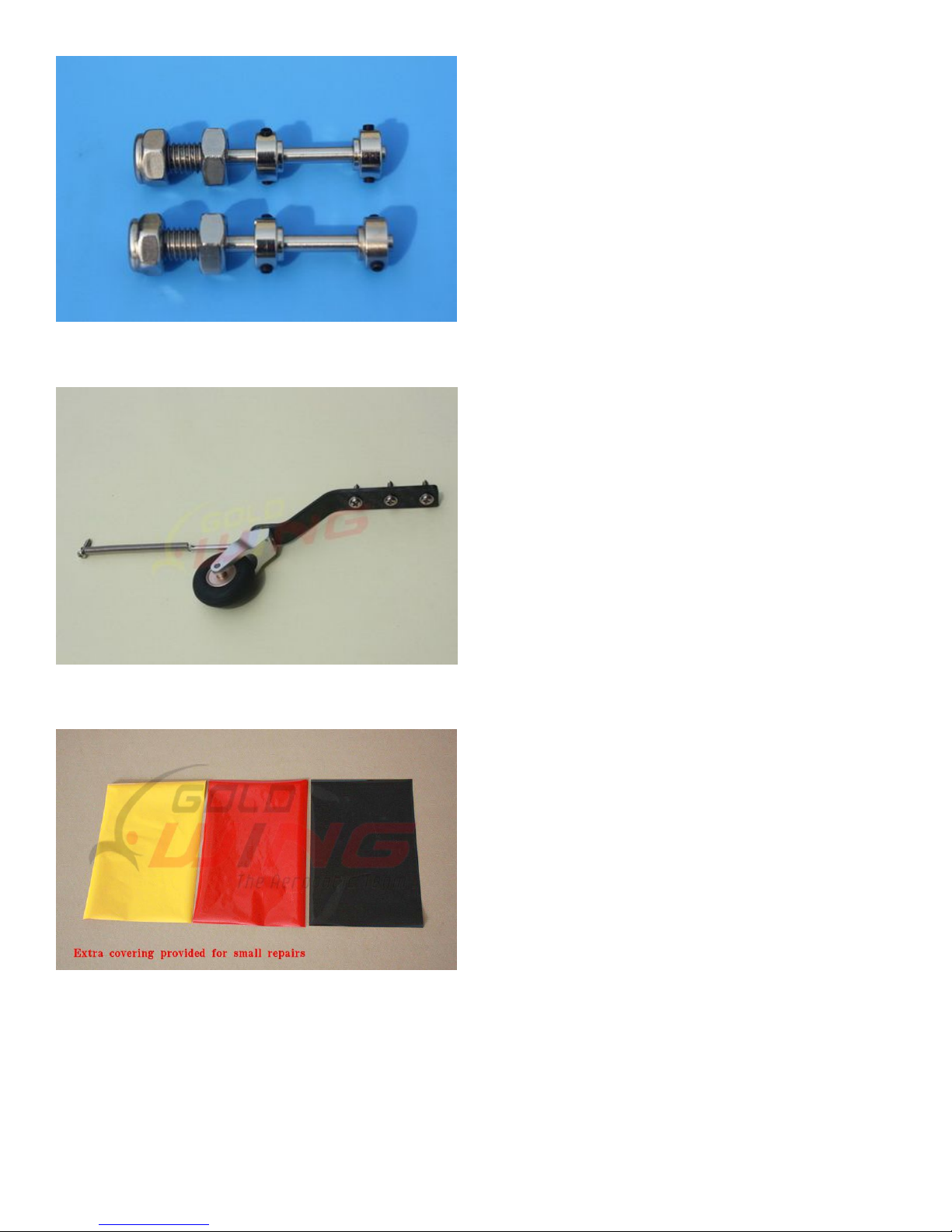
Ball link assembly (Bag No. KAG00122): 8 for ailerons & elevator & rudder.
Page 14
Alu long arm kits: 4 single arms for ailerons and elevator and rudder.
Servo lead safety clips:5 pcs (Bag No. KAG0021)
Alu Main wheels:2pcs(Bag No. KAG0157)
New axle kits (Bag No. KA03CH)
Page 15
Carbon fibre tail wheel assembly with CNC machined metal parts, including the aluminium tail wheel
hub. (Bag No. KAGC103)
Extra covering provided for small repairs
4 allen key wrench (Bag No. KA03CE)
Page 16
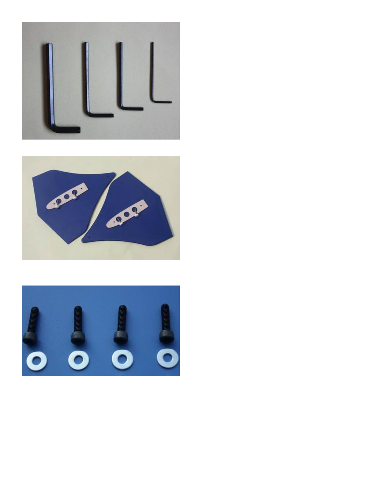
Side force generators (mounted with four M3X18 hand bolts and 2 balsa sheets)
Screews for landing gear: 4(4x20mm) hexagon bolts and 4 washers
Bolts & washers for cowl: 4(3x14mm) Hexagon bolts and 2(10mm) PTFE washers and 2 wsahers
Page 17
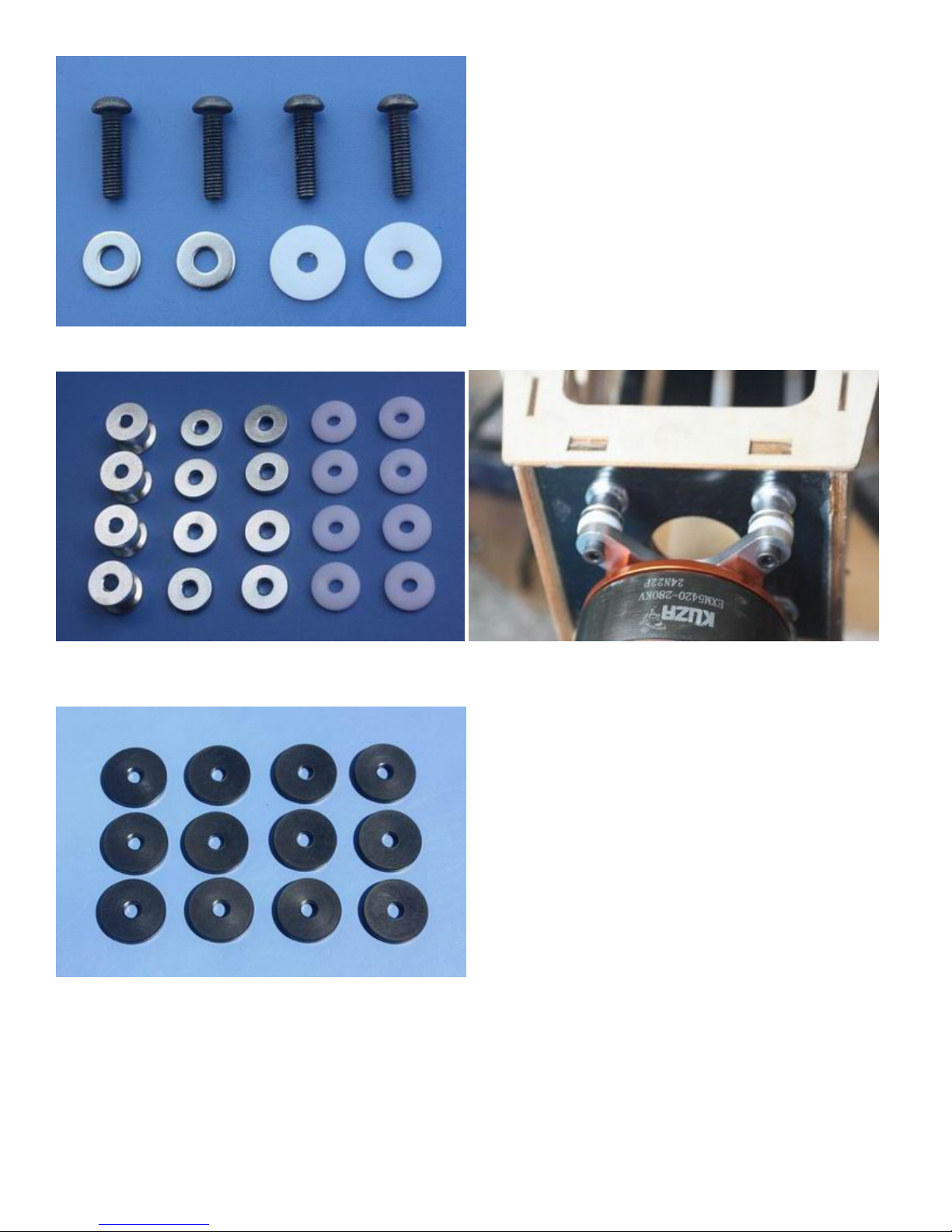
20 POM & ALU washers for 120E motor
Gas engine washers for 30CC version: 12(20mm) POM washers
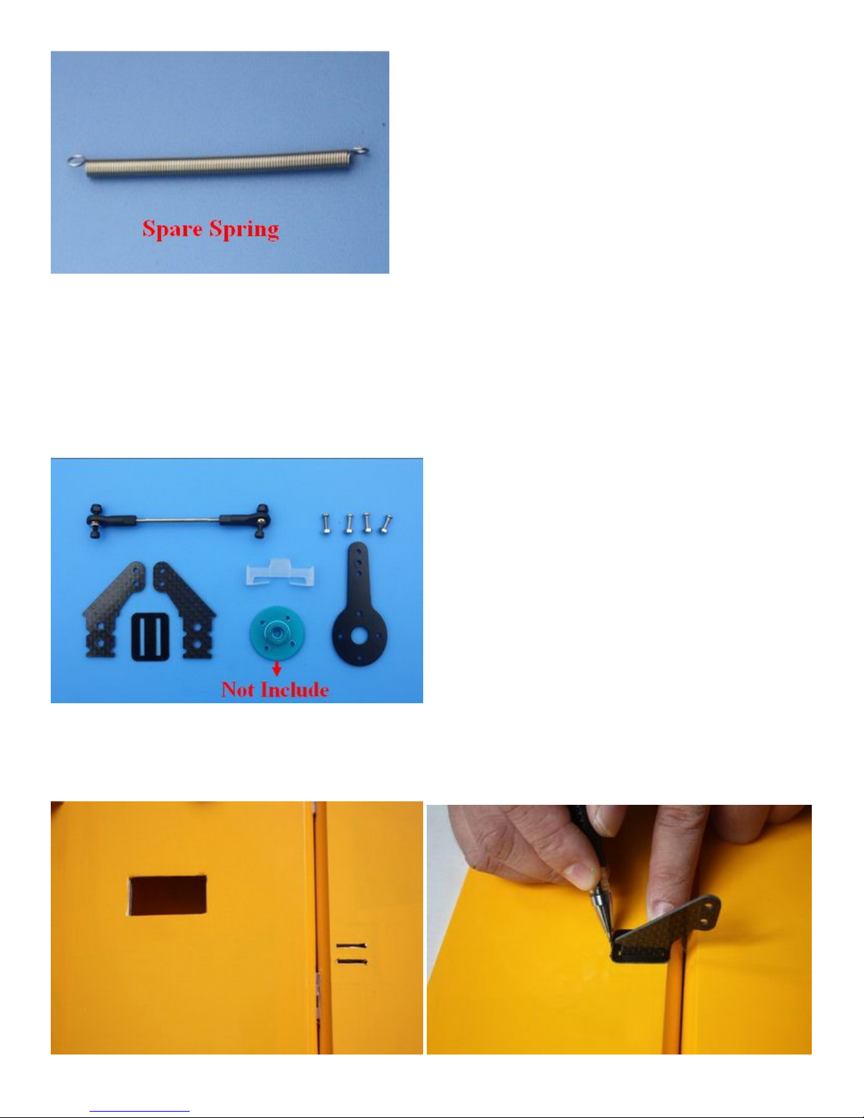
Spares bag(Two spare wing bolts & One spare tail wheel spring)
Page 18

RUDDER ASSEMBLY
1. Rudder pushrod linkage set. NOTE: Rudder is Pull-push style.
2. Locate rudder, 2 control horns and base plate. Rudder is driven by pull-push rod, servo bay is on the right
side of the fuselage.
3. Locate the slot for control horn on rudder, remove the covering over the slot with heated soldering iron or
sharp hobby knife, and make sure you do it on the right side of the aileron. Insert control horn into base plate
then into the slot, trace the edge of base plate with hobby knife then remove the underlying covering.
Page 19
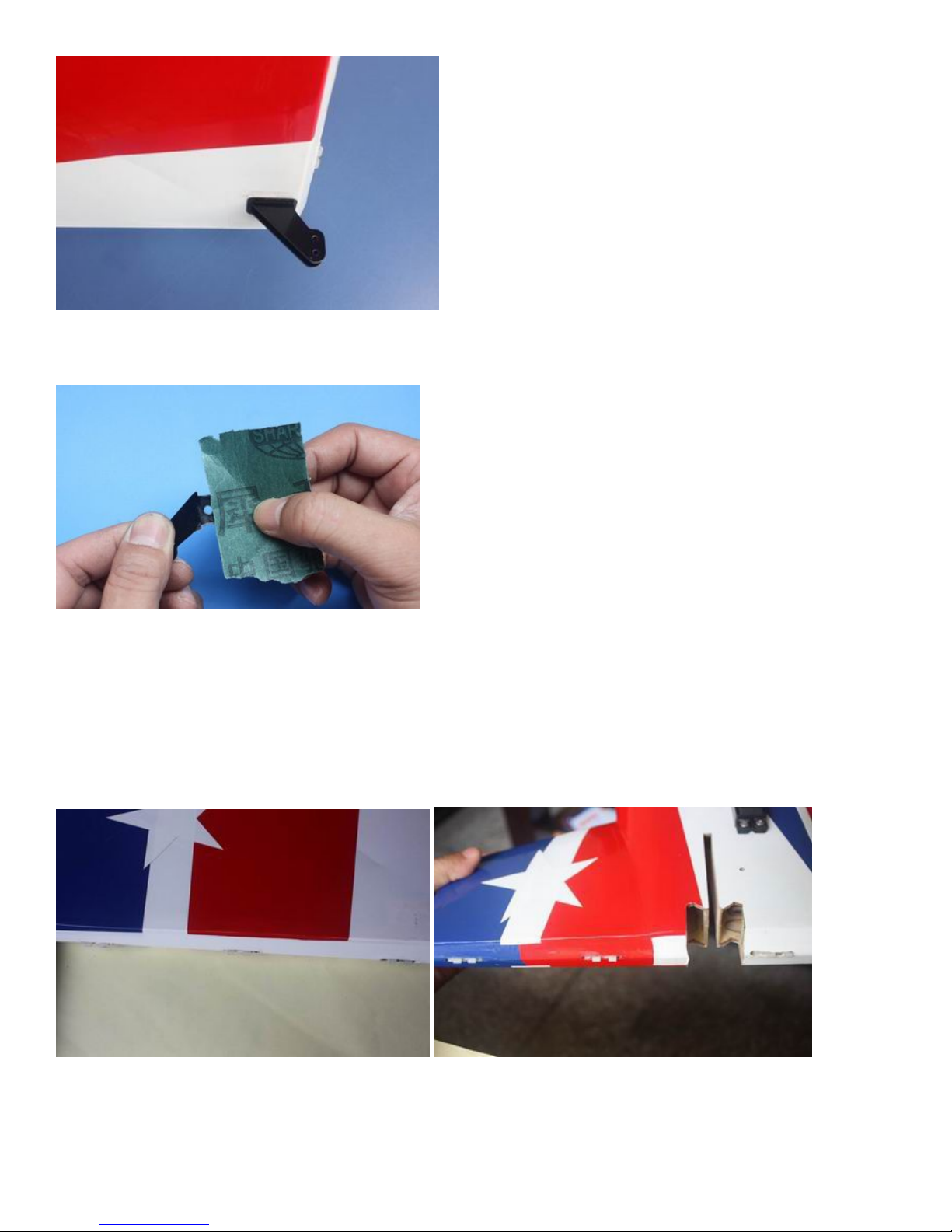
4. Use some fine sandpaper to roughen up the root of control horn where will be glued into the slot.
5. Fill the slot and coat the root of control horn and the bottom of base plate with 30 minute epoxy, insert the
horn into the slot, press it down firmly. Wipe off excessive epoxy with alcohol wipes. Set aside until cured.
Pre-hinged control surfaces
6. The rudder control surface is Pre-hingeds.
7. Cut the covering from the rudder servo slots from corner to corner and iron down inside the openings.
Connect servo wire extensions to your servos and secure the connections with the supplied clips. Feed the
Page 20
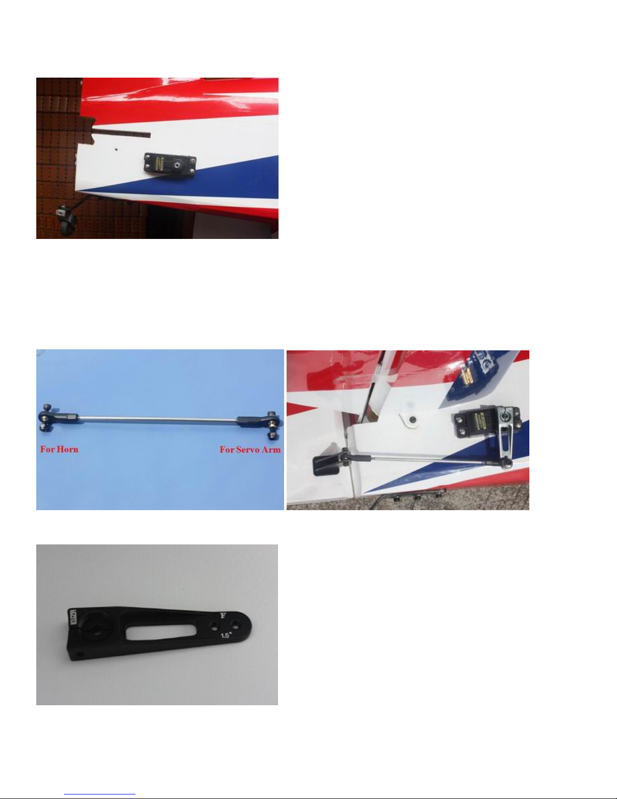
servo wires into the fuselage. The screw holes for servo mounting are laser pre-drilled, it is advisable to
apply some thin CA to strengthen them, Install the servos and screw firmly in place.
8. Use your radio to set the center of servo and then assemble and adjust the length of the control rod. The
servo arm should be as close to perpendicular to the control rod as possible while the aileron is at neutral.
Double check all screws, bolts and nuts to assure proper installation and operation without binding. Once
satisfied, permanently attach the ball links to the servo arms and horns with the supplied screw and nut.
9. We recommend using KUZA 1.5” aluminium CNC servo arm (sold separately) for rudder control.
Page 21
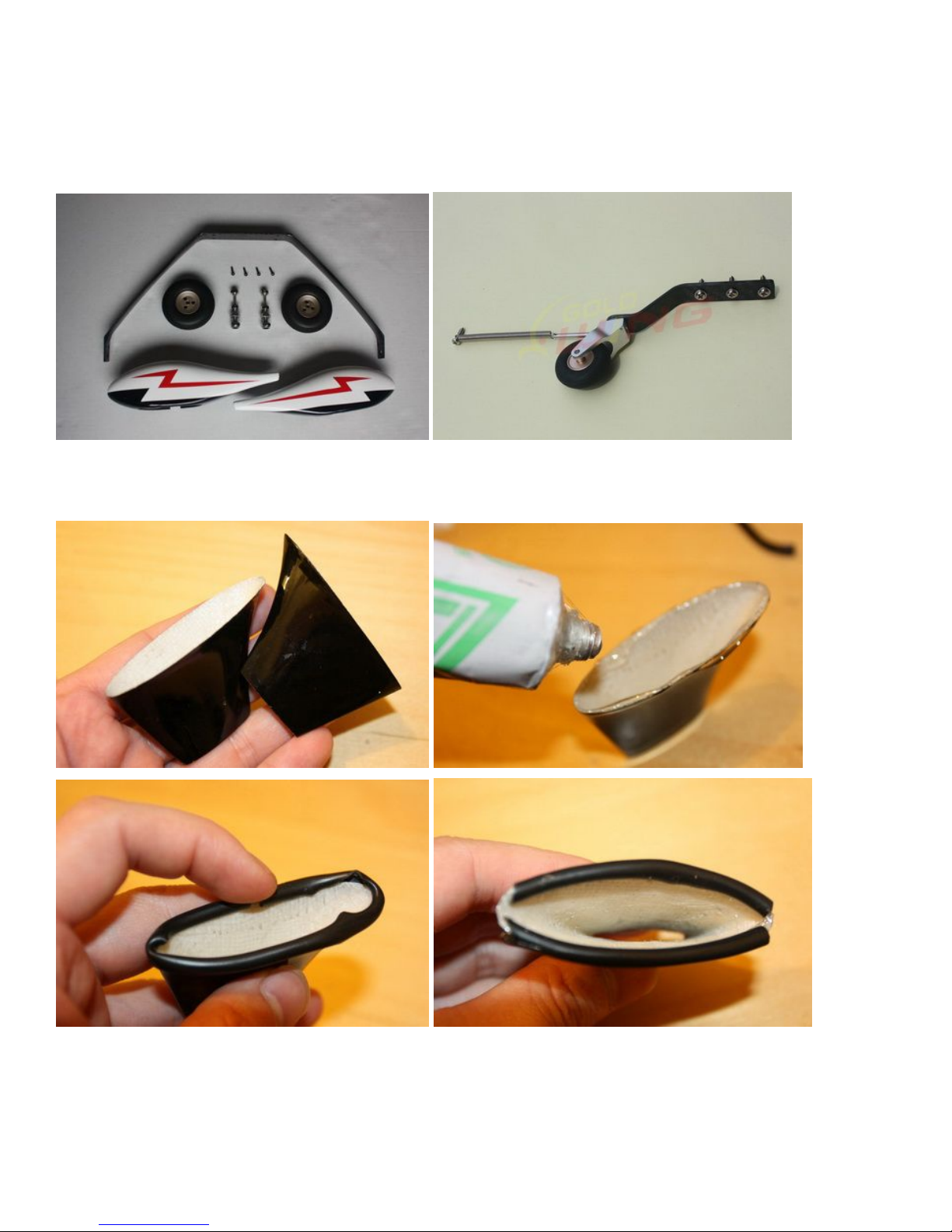
LANDING GEAR ASSEMBLY
NOTE: There are pictures of different planes in this manual, however, this plane’s landing gear is assembled the
same way.
1. Locate the supplied main and tail wheel landing gear parts and sort them out on your workbench.
2. Locate the 2 fiberglass landing gear fairings and the black silicone tubing. Cut through one wall of the
tubing along the length. Press the tubing onto the edges of the fairing as shown and secure glue.
Page 22
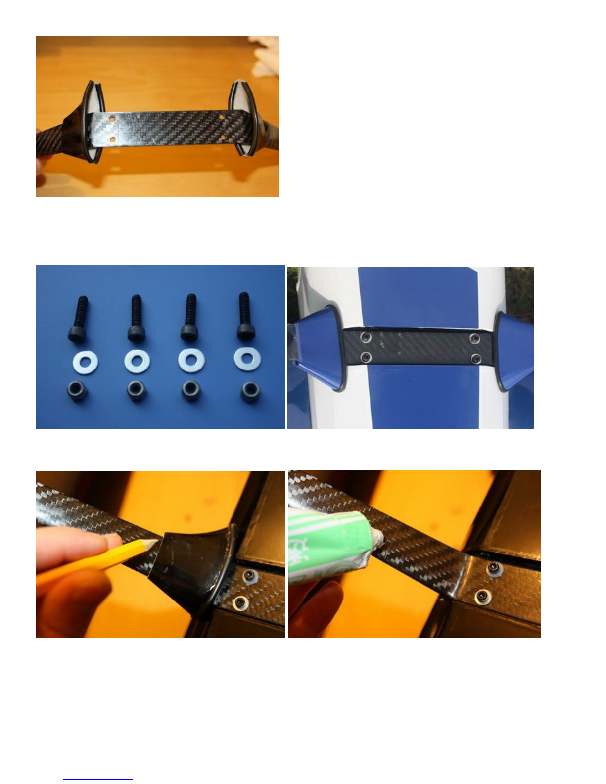
3. Bolt the main gear to the bottom of the fuselage using the supplied screws and stainless steel Self-locking
nuts. Place the bolts in through the can tunnel opening with appropriate size spanner. Remember the gear
will rake forward.
4. Adjust the position of the landing gear fairings, the secure with glue (shoe goo type).
Page 23

5.Loosen out the inner nut, then apply thread lock to the axle. Tighten the nut back in place, allow the thread
locker to dry.
6. Install the main wheel axles to the composite landing gear and tighten the nylon-insert lock nut. Install one
wheel collar onto the axle. Use a second wheel collar as a guide to leave a gap on the inboard of the axle. Use
a small drop of thread-lock and tighten in place. Slide the wheel onto the axle and install a second wheel collar
also using thread-lock on the set screw.
Page 24

7. Fit the wheel pant in place and install using the two supplied bolts and washers. Use thread-lock to secure
the bolts in place. Repeat the above steps for the other main gear.
Page 25
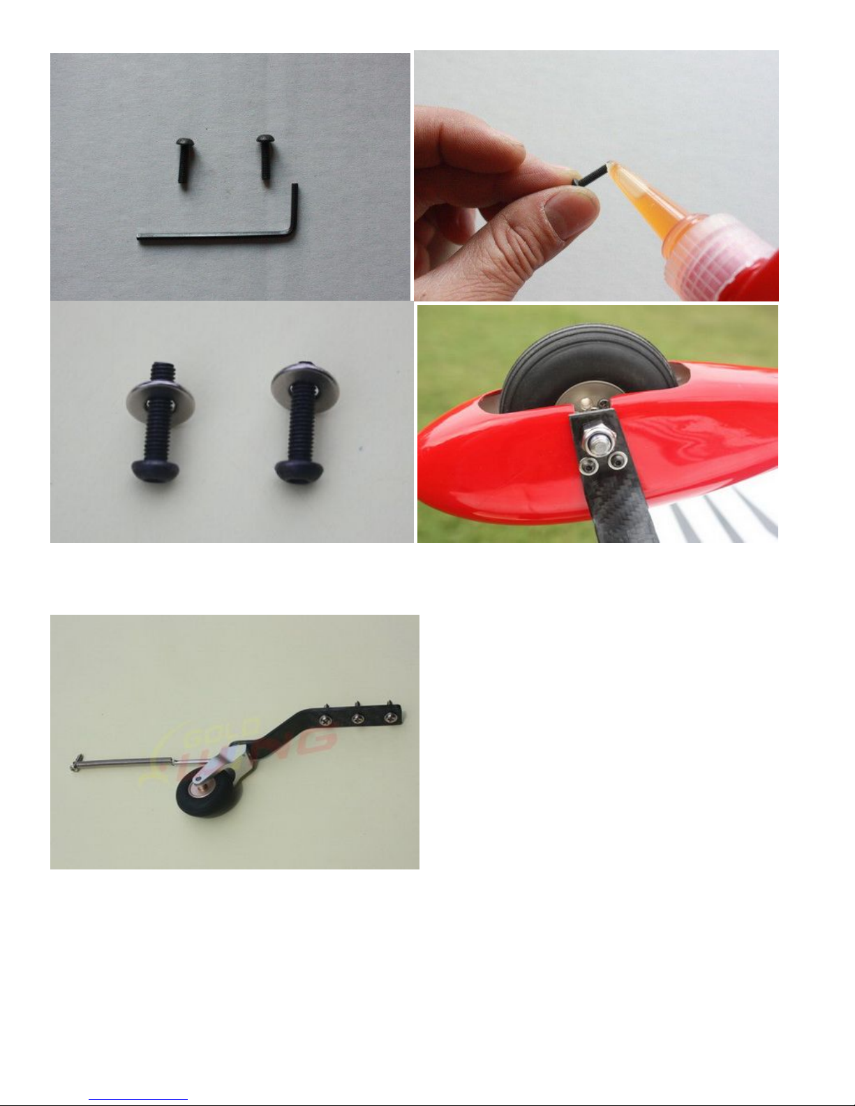
8. The tail wheel installation is very simple, the factory has installed most of the accessories, see the below
picture.
9. Line up the caron fiber assembly onto the body of the aircrtaft and use the holes as a drill guide. Use a 2mm
drill bit as a pilot hole, then apply thin CA to harden the wood. Use the three self tapping screws and secure the
assembly into place.
Page 26
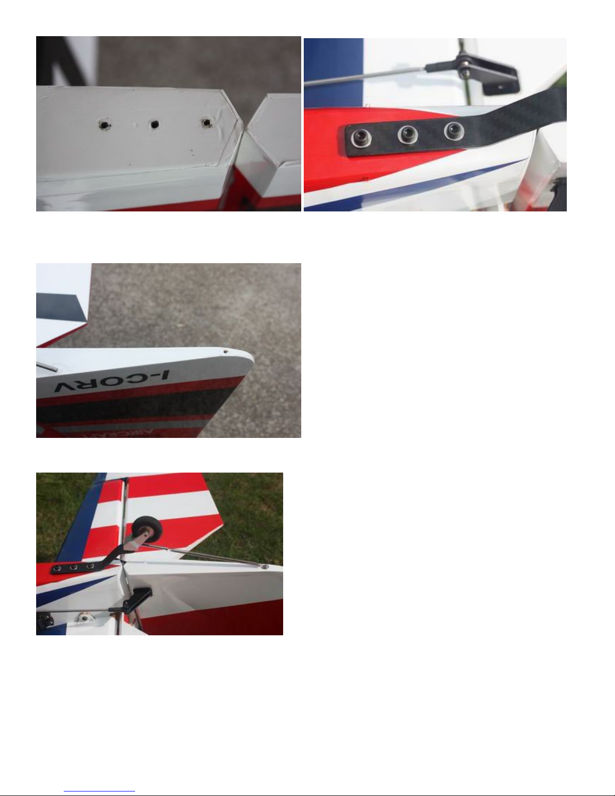
10. Drill another 2mm pilot hole at the end of the rudder and apply thin CA. It needs to be in a position where
the spring is tensioned. Use a self tapping screw to secure in place.
11. The below is a picture of correctly installed tail wheel assembly.
NOTE: One spare tail wheel spring is included in the spare hardware pack.
Page 27
WINGS ASSEMBLY
NOTE: There are pictures of different planes in this manual, however, this plane’s wings is assembled the same
way.
1. Aileron push rod linkage set.
2. The aileron control surfaces is Pre-hingeds.
Locate the slots for the aileron control horn and remove the covering with a sharp knife. Place the horns into
position and the cover over the top to work out the area needing to be removed.
Page 28
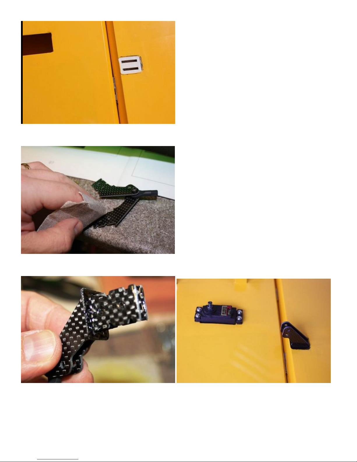
3.Rough the area of the horn that will be glued in place.
4.Using 30 minute epoxy glue the horn and plate into the aileron.
5.Screw holes for servo mounting are pre-drilled by laser in factory, install servo with 4 self threading
screws.Fit a metal servo arm centering with your radio.
Page 29

6.Locate the included aluminum long servo arm, enlarge control holes with 2.5mm drill bit
7.Using the pushrods connect the servo arm to the horn. Remember that on the pushrod one end is reverse
threaded.
Page 30

Use M2.5 screws and nuts to connect the pushrod. Set it so the aileron it level when the arm is at 90 degrees.
REPEAT FOR THE OTHER SIDE
8
.
We recommend using KUZA 1.5” aluminium CNC servo arm (sold separately) for wing
control.
ELEVATOR ASSEMBLY
1. Push rod linkage set for elevator
Page 31

2. Find the control horn slots on bottom side the elevators, use the method described in 1.2-1.4 to install
control horns for elevators.
3. Elevator horn slot is located on the left side of elevator. Remove covering over the hole for horizontal
stabilizer on fuselage. Removing covering on the central part of horizontal stabilizer is recommended
for better glue bonding. Insert the horizontal stabilizer into fuselage, make sure it’s centered. Apply
thin and gap-filling medium CA to glue it in place.
4
.
The Elevator control surface is Pre-hingeds.
Page 32
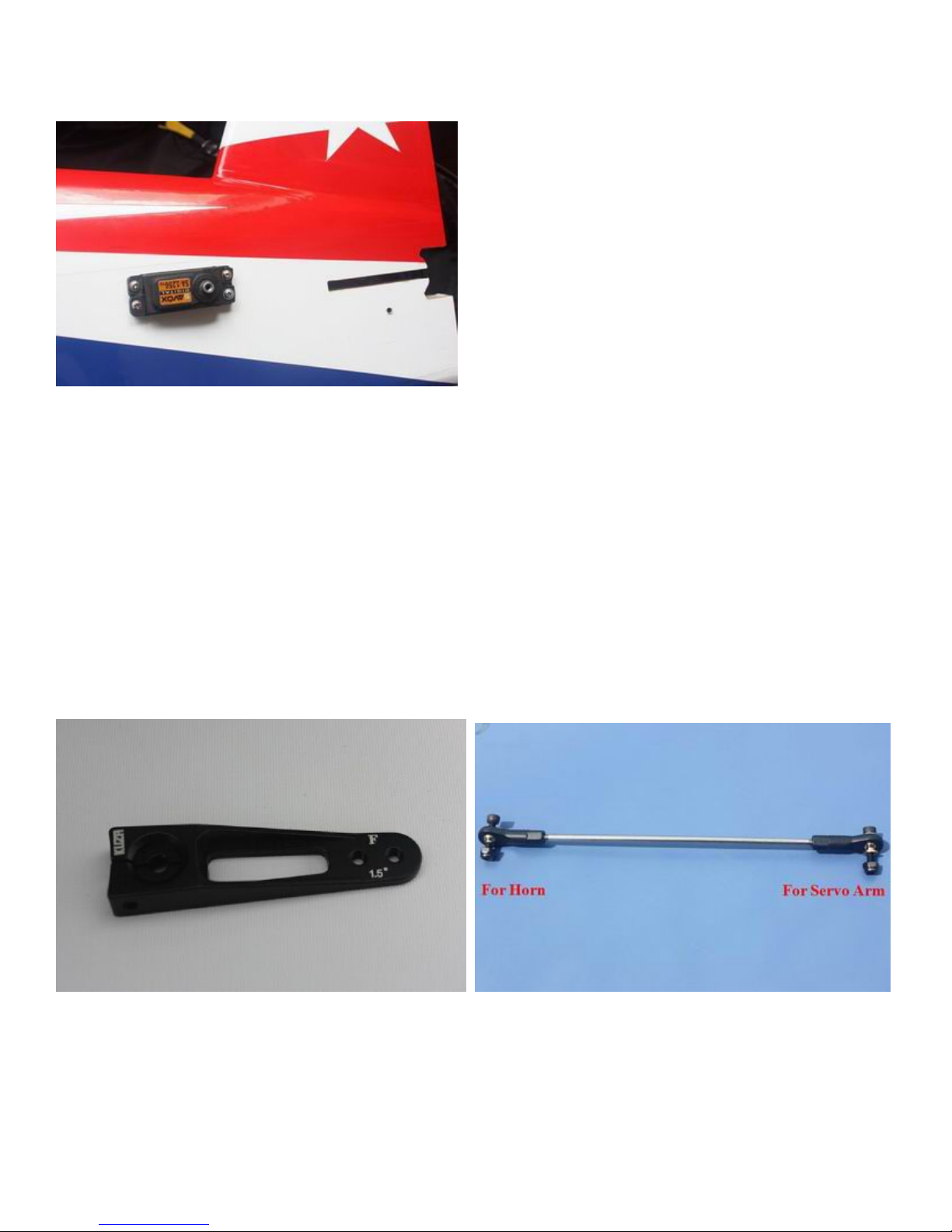
5. Locate the slots for elevator servo, remove covering. Connect wire extension to your servos before
feeding the wire into fuselage. Install servo with screws supplied by servo manufacturer.
6. Use your radio to set the servo center position and install the large control horn onto the servo.
Assemble the control rod and ball links and adjust the control linkage for proper geometry. When
satisfied, screw the ball link to the servo arm and control horn. KUZA 1.5” aluminium CNC servo
arm is recommended for elevator control, the servo arm should be as close to perpendicular to the
control rod as possible while the elevator is at neutral. Double check all screws, bolts and nuts to
assure proper installation and operation without binding.
Page 33
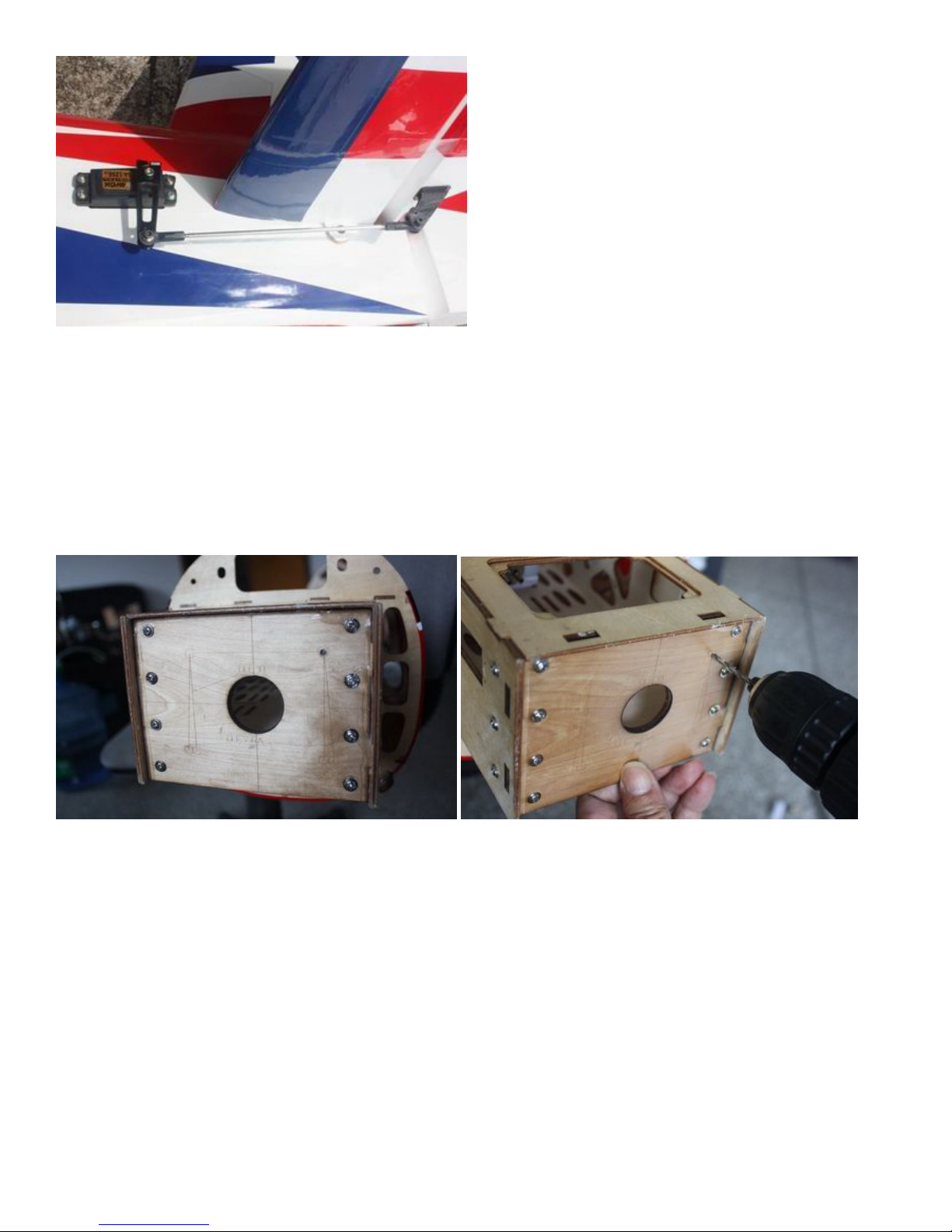
For 30CC version,Engine, Exhaust, & Fuel System Installation
Engine Installation
NOTE: There are pictures of different planes in this manual, however, this plane’s engine is assembled the same
way.
1. Select the correct guide for your engine and drill the holes and cut out the center as indicated. Notice that the
engine center line is offset to the left to compensate for the right thrust built into the engine box.
2. Fit the Cowl and measure the distance from the engine bulkhead to the front of the cowl, add approx 2-3mm
for the back plate and this is the length that your engine should be set. Using the correct length stand offs,
mount your engine securely using bolts, washers, and locknuts. The use of thread-lock is also highly essential
for the engine bolts.
Page 34
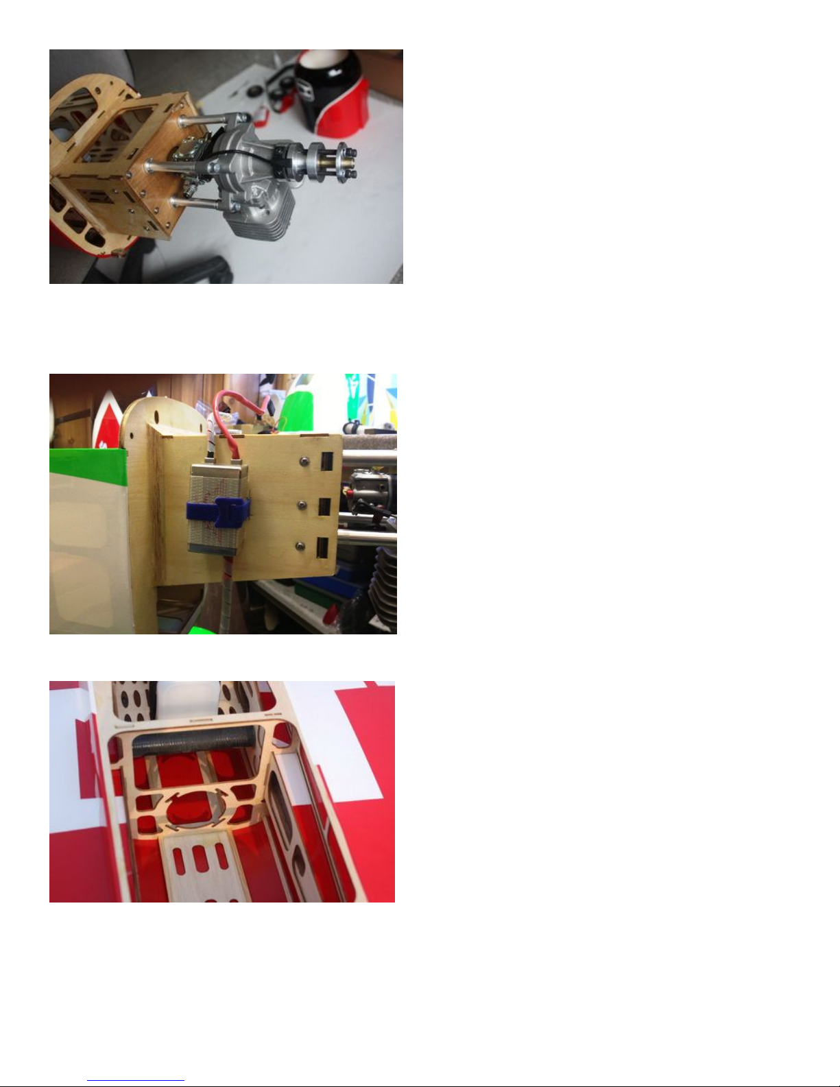
3. Mount the ignition module according to the manufacturer’s instructions. The best place to mount it is on the
side of the engine box. Secure the pickup lead and ignition wires with zip ties so that they do not vibrate or
touch any hot part of the engine or exhaust.
4. The following pictures show how to install a canister.
Page 35
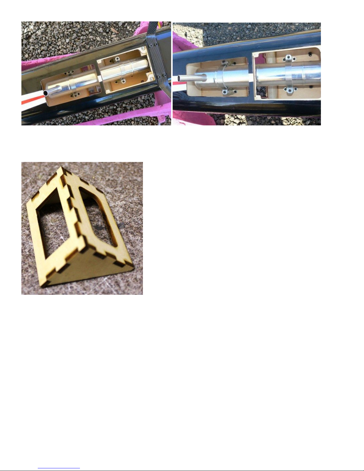
4. Assemble the throttle servo mount using the supplied laser cut parts or there is a servo cutout in the bottom
of the engine box for 28cc-38cc engines. Mount your throttle servo and complete your linkage setup. A hole
will need to be drilled on the firewall to allow the pushrod to connect to the throttle arm on the carb.
6. An extra servo can be fitted for choke or a mechanical linkage can be used.
7. The KUZA new 360cc fuel tank is preassembled. Complete the installation in the fuselage using zip ties or
velcro straps to hold the tank in position. Connect a fuel line between the tank and carb, a fuel line between the
tank vent and the bottom of the fuselage, and a fill line to a fueling port which can be mounted on the fuselage
side opposite your ignition switch. Make sure your vent line does not come close to any hot exhaust part such
as the muffler or canister. We recommend the use of small zip ties or fuel line clamps to secure the lines to the
tank.
Page 36

A barb on the bottom of the fuselage can be fitted for the vent.
Installation of KUZA Fuel Dot and Fuel Vent Line Plug (Not included)
1. From June 2015 and on, all Goldwing gas airplanes are made ready for KUZA fuel dot and
vent line plug. Available in three colors: black, red and blue.
2. Installation of KUZA CNC Aluminum Fuel Dot
Sites for KUZA fuel dot installation are pre-cut on both sides of the fuselage, you may install it
on either side. Use shape knife to remove the covering.
Page 37

Secure the housing of fuel dot with supplied 2.5 mm self-tapping screws, then plug and install
the fuel line to complete the setup of fuel dot.
Page 38
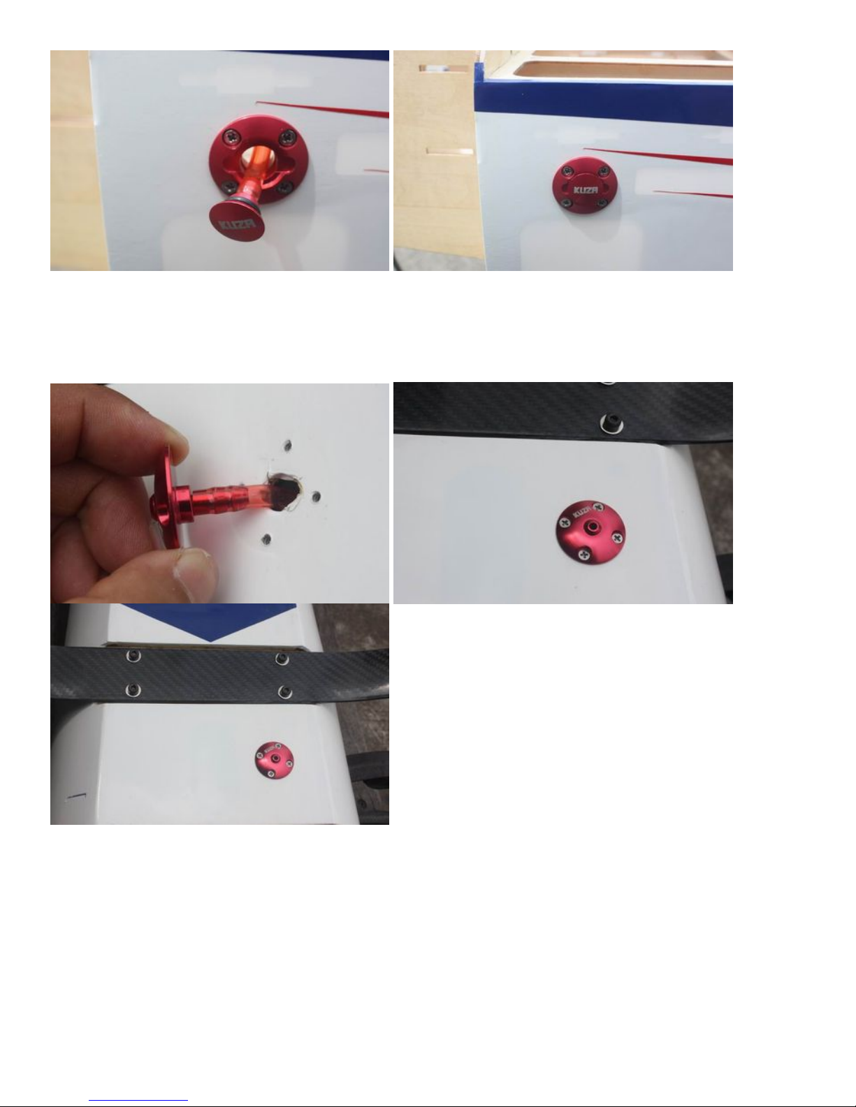
3. Installation of KUZA CNC Aluminum Fuel Vent Line Plug
Similarly, two sites for vent line plug installation are available at the bottom of the fuselage.
Secure KUZA vent line plug with four 2.5 mm self-tapping screws as shown below.
120E Electric version Motor Installation
1. Find the washers for motor installation in the 120E version hardware package.There are 8 POM washers,and
16 ALU washers.
Page 39
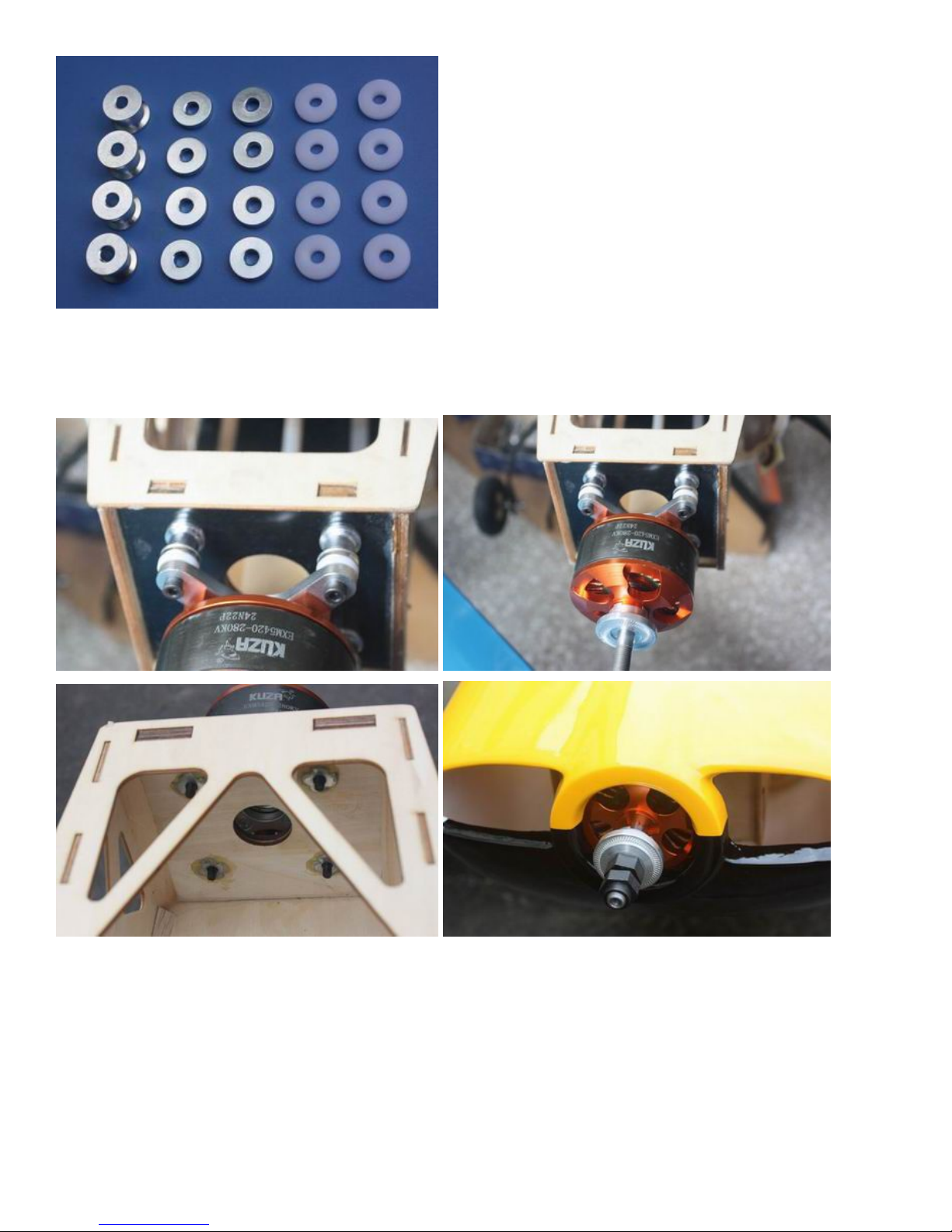
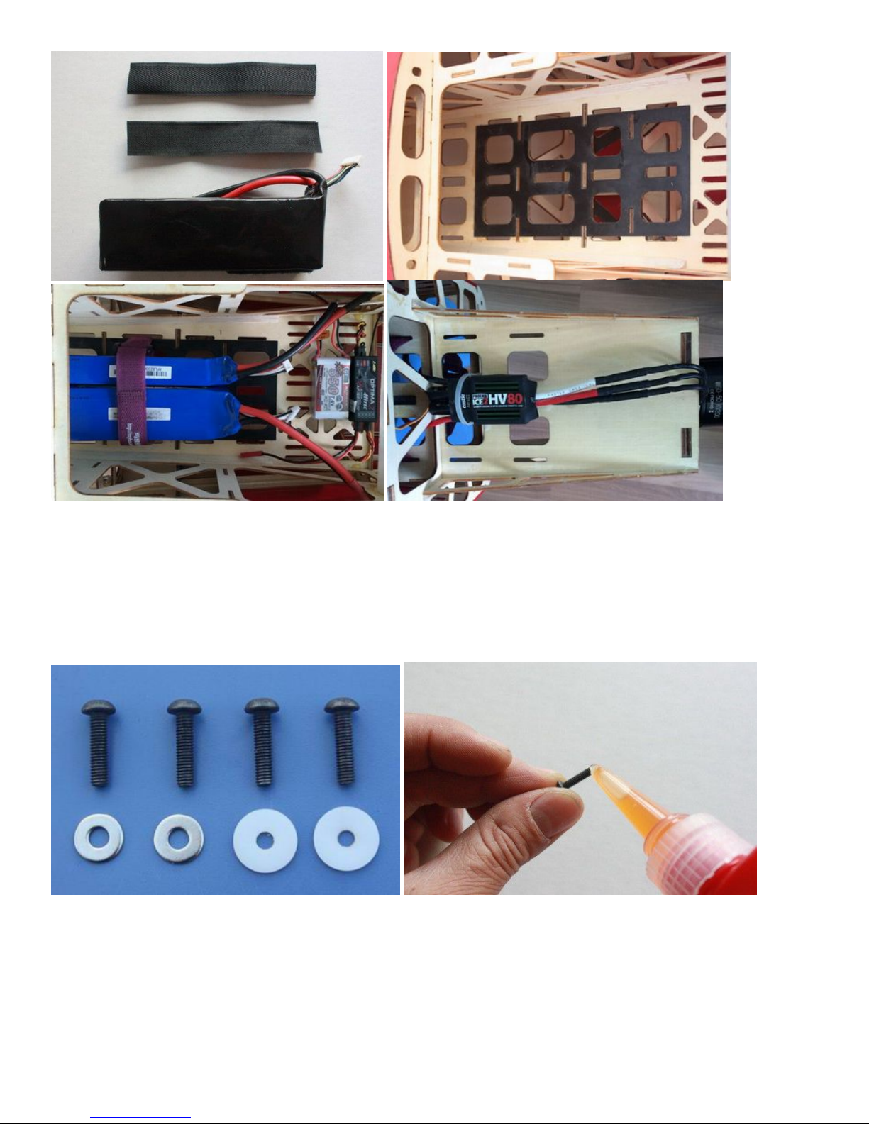
2.Blind nuts are pre-installed behind the firewall. Since the position of cowl is fixed and length of
motors varies, you may need to use provided washers to position you motor properly.
3. Fix the battery with both Velcro and straps.
Page 40
COWLING INSTALLATION
NOTE: There are pictures of different planes in this manual, however, this plane’s cowling is assembled the
same way.
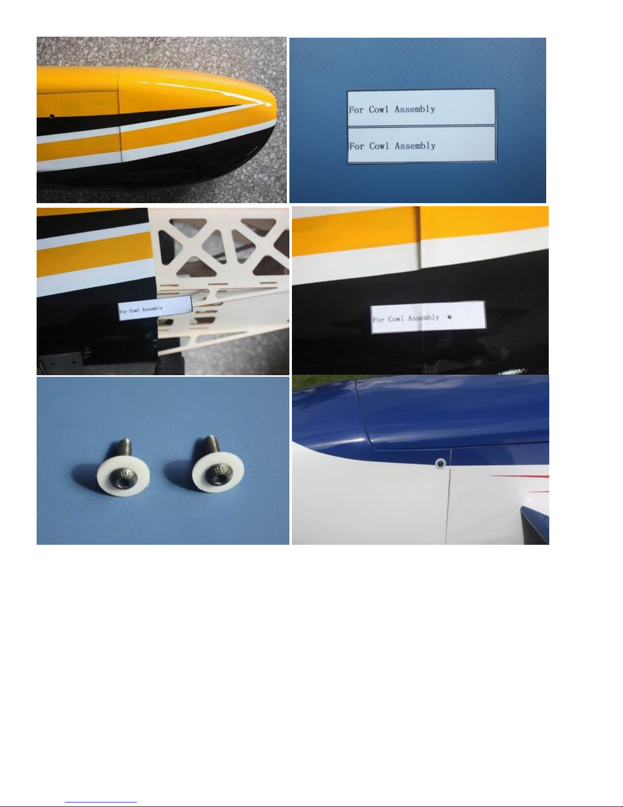
1. The cowl is secured with four 3 X 14mm bolts and washers.Apply nutlock onto the bolts as the vibration
from the gas engine will shake them come loose.
2. Labels are provided for aligning the drill holes for the cowl. Stick then on without the cowl, mark the hole.
Fit the cowl then press back down. The hole will then show the area to drill. Sere below.
Page 41
FINAL RADIO SYSTEM INSTALLATION
Whether you use 72 MHz systems or the newer 2.4 GHz systems, correct radio installation and care is vital to
the safe and reliable operation of your aircraft. Follow the manufacturer’s instruction for installation guidance
of receivers and batteries paying attention to factors such as vibration isolation, adequate cooling, and
clearances.
1. Mount your receiver(s) securely in a location which provides a clean and maintenance free solution to
your setup. All servo wires should be neatly routed and secured in place so they will not come loose or
flop around during flight.
2. The fuselage ply sides provide space to mount your switches just below the canopy. Mount your
switches according to the manufacturer’s instructions and route your wires safely and securely as above.
3. Your receiver battery(s) can be mounted in a variety of locations depending on your balance needs.
Regardless of where you mount your batteries it is vital that they are very secure with no possibility of
Page 42

coming loose. Use double sided Velcro to hold the batteries from sliding around and then use zip ties or
Velcro straps to secure them tightly in place.
4. Servo and battery leads are the life blood of your aircraft. Make sure all wires are top quality and
connectors are tight and display no loose pins or frayed wires. Servo clips are provided in the kit for
your convenience. These servo clips can even be glued to the wood structure using CA if desired.
5. Check all radio programming and control surface operations thoroughly before your initial flight. Check
your radio range according to the radio manufacturer’s instructions both with the engine off and running.
Balancing and Pre-Flight Checks
Most state of the art aerobatic aircraft allow for a wide margin for balancing depending on what level of
precision or freestyle flying the pilot prefers. To perform properly without being too pitch sensitive, you
must not go too aft on the CG. GoldWing RC recommends an initial CG setting of 108-126mm(4.25-5
inches) behind the leading edge of the wing at the root. More experienced pilots may want to set the
CG further aft for more 3D capability. Varying weights of engines and radio gear will dictate how you
should install each. The batteries can easily be located pretty much anywhere in the fuselage. For those
using a heavy engine, servo cutouts are provided in the rear of the fuselage for the rudder servos. These
options should allow you to balance the model without adding any weight.
Note: The best way to check your balance is to trim for level flight at about 1/2 to 3/4 throttle and then roll
inverted. The aircraft should maintain level flight with very little to no down elevator input. If the aircraft
climbs when inverted then you’ve probably got your CG too far aft. If the nose drops more than slightly, then
you are most likely nose heavy.
Recommended control surface deflections:
Low Rate
High Rate
Elevator
15 degrees
45-50 degrees
Rudder
25 degrees
40 - 45 degrees
Ailerons
25 degrees
35-40 degrees
Final Assembly and Pre-Flight Inspections
1. Before arriving at your flying field, be sure all your batteries are properly charged and all radio systems are
in working order.
2, Installation of the rudder
The rudder is removable for convenience in transportation, it is connected to fuselage by inserting a 1.2 mm
steel rod through the hinge line.
Page 43
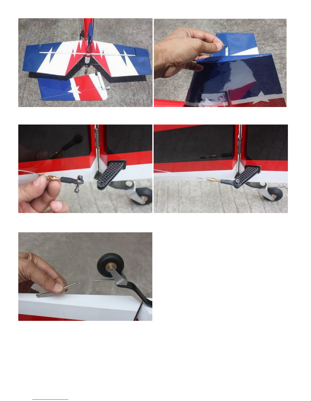
Then install pull-pull ball links on control horns.
Hook up the tail wheel spring.
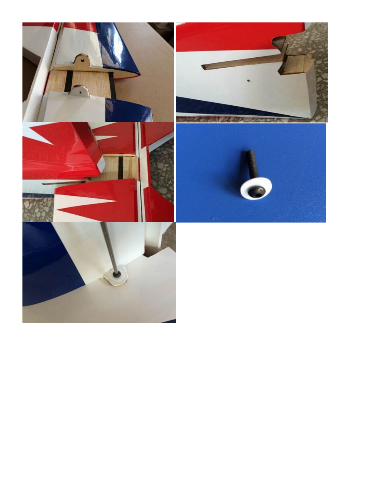
3.Installation of stab
Also the stab is removable for convenience in transportation,
Attach elevators with 3x12mm Hex-head bolts and 10mm PTFE washers. Check these after every flight.
Page 44
4. Install the wings onto the fuselage being careful to align the wing tube with the wings and not force it. The
wing tube may be initially tight but will loosen after some with use. Guide your servo wires into the fuselage
openings and connect to the correct aileron channels. Servo clips are recommended. Once you have the wings
fully seated in the fuselage tighten the wing bolts inside the fuselage.
Page 45
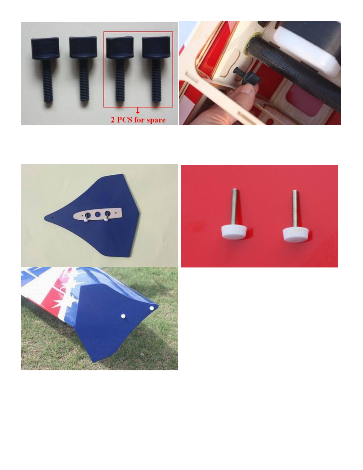
5.Side force generators Assembly.
Cut the wing film needed to be install the SFG. Fixed the SFG Use M3X18 hand bolts and balsa sheets.
Installation of the SFG is optional.
6. Fill your fuel tank making sure your vent line is not plugged or capped. With the canopy off, this is a good
time to check for any fuel leaks.
7. Check all control surfaces for secure hinges by performed a slight tug on the control surfaces and observing
if there is any give in the hinges. Check all control rods, ball links, servo screws, etc. for correct operation and
installation.
8. Check your batteries and perform a range check once again with the engine off and running. Be sure all
surfaces are moving in the correct direction and the correct amount for your flying setup.
Page 46
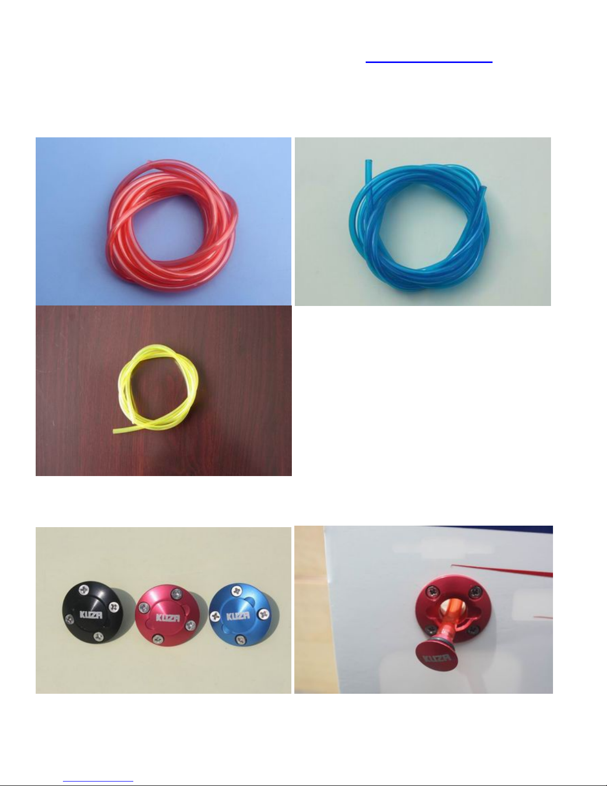
9. You are now ready for your maiden flight! Good luck and enjoy your new aircraft! If you have any
comments or questions about this manual or the aircraft please email [email protected].
Recommend Accessories(Not included):
* KUZA Gas Fuel line size: 6X3.5mm 3 color to choose: red , blue, yellow
No. KAG006131R or KAG0061U or KAG0061Y
* KUZA CNC Aluminum Fuel Dot 3 color to choose: black, blue, red No. KAG0231B or
KAG0231U or KAG0231R
* KUZA CNC Aluminum Fuel Vent Line Plug 3 color to choose: black, blue, red
No. KAG0232B or KAG0232U or KAG0232R
Page 47
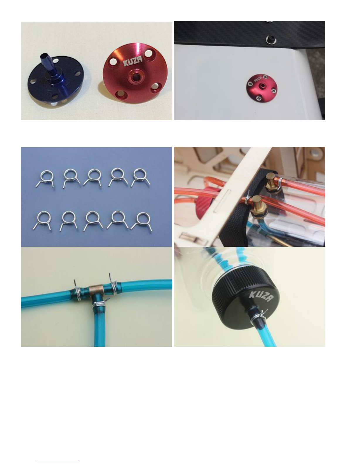
* KUZA Fuel line clips 10PCS No. KAG02454
* KUZA Heavy duty 7075 aluminum Servo Arm
For Futaba servo(25T):
39mm/1.5in Single No. KAG0S72F
Page 48
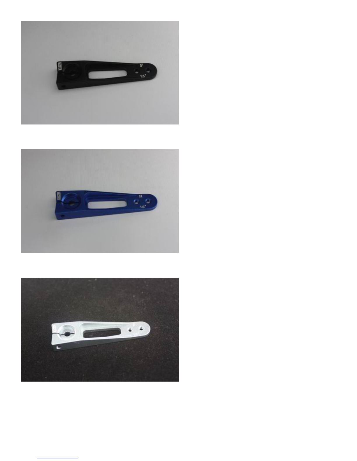
For Hitec servo(24T):
39mm/1.5in Single No. KAG0S72H
For JR servo(23T):
39mm/1.5in Single No. KAG0S72J
Page 49
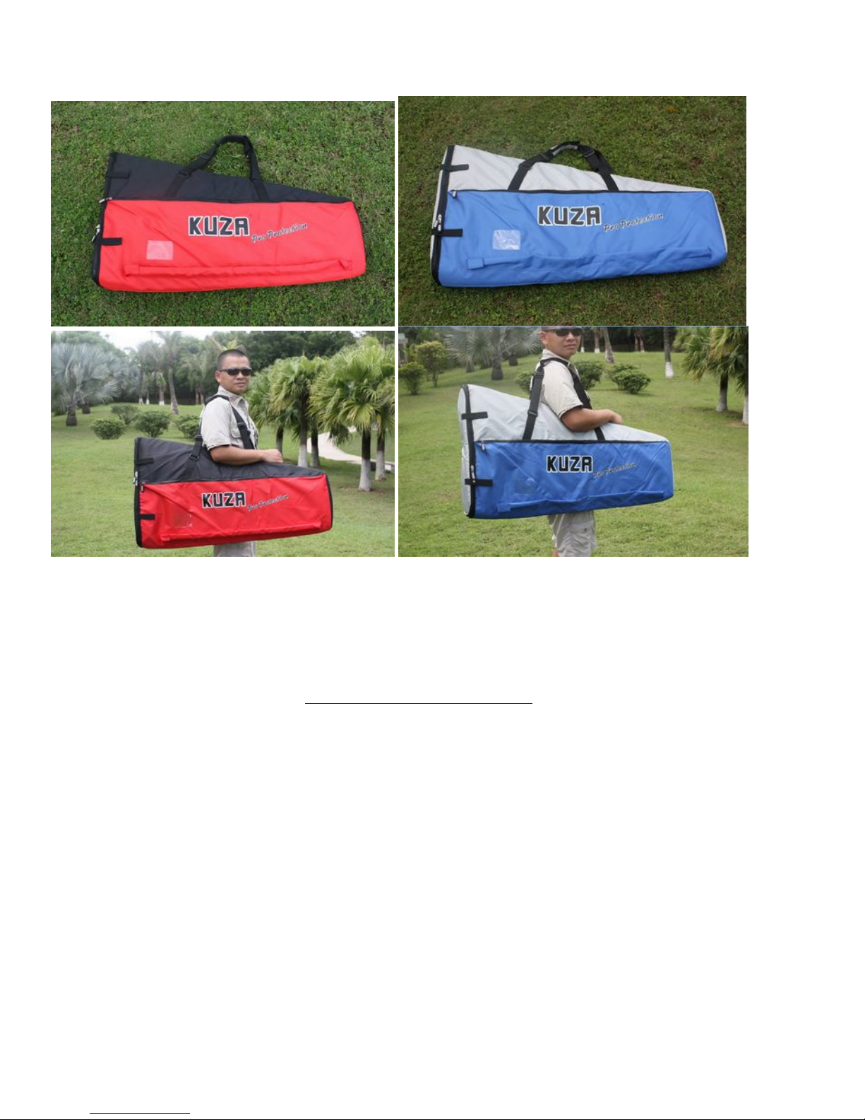
* KUZA new Wingbag for 73in EXTRA Two color to choose: red/ black, blue / silver No.
KAG0093
GOLDWING RC
www.goldwingrc.com
 Loading...