


150Mbps Wireless Router
GW-WR150N/GW-WR150ND
User Manual
150

GW-WR150N/GW-WR150ND 150Mbps Wireless Router User Manual
Contents
1 Safety Precautions ............................................................................................. 3
2 Overview ............................................................................................................ 4
2.1 Product Introduction .............................................................................. 4
2.2 Packing list ............................................................................................ 4
3 Hardware Description and Hardware Installation............................................... 5
3.1 Front Panel and LED Status.................................................................. 5
3.2 Rear Panel and Interface Description ................................................... 6
3.3 Hardware Installation............................................................................. 7
3.3.1 System Requirements ................................................................7
3.3.2 Before You Begin ........................................................................ 7
3.3.3 Connecting the Device ............................................................... 8
3.4 Operation Range ...................................................................................8
3.5 Roaming ................................................................................................8
4 TCP/IP Settings and Wireless Connection Introduction................................... 10
4.1 TCP/IP Settings ................................................................................... 10
4.2 Wireless Connection Introduction........................................................15
5 Logging In to the Web Page............................................................................. 19
6 Web Configuration ...........................................................................................21
6.1 Setup Wizard ....................................................................................... 21
6.2 Running Status .................................................................................... 26
6.3 Network Settings ................................................................................. 27
6.3.1 Operating Mode ........................................................................ 28
6.3.2 LAN Interface Settings.............................................................. 29
6.3.3 WAN Interface Settings ............................................................30
6.3.4 MAC Address Cloning............................................................... 39
6.4 Wireless Settings.................................................................................40
6.4.1 Basic Settings........................................................................... 41
6.4.2 Wireless Security Settings........................................................ 43
6.4.3 Wireless MAC Address Filter.................................................... 53
6.4.4 Advanced Wireless Settings.....................................................54
6.4.5 Wireless Client List ................................................................... 63
6.4.6 WPS Settings............................................................................ 64
i

GW-WR150N/GW-WR150ND 150Mbps Wireless Router User Manual
6.4.7
WDS Settings ...........................................................................69
6.5 DHCP Server ....................................................................................... 83
6.5.1 DHCP Service........................................................................... 84
6.5.2 Static Address Allocation.......................................................... 85
6.5.3 DHCP Client List....................................................................... 86
6.6 Forwarding Rule ..................................................................................87
6.6.1 Virtual Server ............................................................................ 88
6.6.2 Port Triggering Settings ............................................................ 90
6.6.3 DMZ Host.................................................................................. 92
6.6.4 UPnP Settings ..........................................................................93
6.7 Security Options ..................................................................................94
6.7.1 Security Settings....................................................................... 95
6.7.2 Advanced Security Settings...................................................... 96
6.7.3 LAN Web Management ............................................................98
6.7.4 Remote Web Management..................................................... 100
6.8 Access Control .................................................................................. 101
6.8.1 MAC/IP/Port Filter Settings..................................................... 102
6.8.2 Web URL Filtering...................................................................104
6.9 Routing Settings ................................................................................105
6.9.1 Static Routing Table ................................................................ 106
6.10 IP Bandwidth Control......................................................................... 107
6.10.1 IP Bandwidth Control Settings........................................... 108
6.10.2 IP Bandwidth Control List.................................................. 109
6.11 IP and MAC Binding .......................................................................... 110
6.11.1 Static ARP Binding Settings .............................................. 110
6.11.2 ARP Mapping Table............................................................111
6.12 Dynamic DNS Settings ...................................................................... 112
6.13 System Tools ..................................................................................... 113
6.13.1 Network Time Settings ...................................................... 114
6.13.2 Diagnosis Tools ................................................................. 115
6.13.3 Software Upgrade ............................................................. 117
6.13.4 Load Default Settings........................................................ 118
6.13.5 Export and Load Settings.................................................. 119
6.13.6 Reboot............................................................................... 120
6.13.7 System Settings ................................................................120
ii

GW-WR150N/GW-WR150ND 150Mbps Wireless Router User Manual
6.13.8
System Log .......................................................................121
6.13.9 Traffic Statistics .................................................................123
7 Troubleshooting .............................................................................................124
iii

GW-WR150N/GW-WR150ND 150Mbps Wireless Router User Manual
About User Manual
This user manual mainly describes how to install and configure the wireless router.
Organization
This user manual is organized as follows:
Chapter Description
Chapter 1 :Safety
Precautions
Chapter 2 :Overview Provides a general overview of the
Chapter 3 :Hardware
Description and Hardware
Installation
Chapter 4 :TCP/IP Settings
and Wireless Connection
Introduction
Chapter 5 Logging In to the
Web Page
Chapter 6 :Web
Configuration
Chapter 7 :Troubleshooting Provides the troubleshooting information.
Provides safety precaution information.
wireless router, and the packing list.
Mainly describes the front panel and the
rear panel of the wireless router and the
procedures for hardware installation.
Provides the information about how to
configure the TCP/IP settings and how to
connect the wireless router wirelessly.
Describes how to log in to the wireless
router.
Mainly describes how to navigate through
the Web pages and how to configure the
parameters.
Features
Support IEEE802.11b, IEEE802.11g, IEEE802.11n, IEEE802.3,
IEEE802.3u, IEEE802.11i, and IEEE802.11e
1

GW-WR150N/GW-WR150ND 150Mbps Wireless Router User Manual
Transmission data rate is up to 150 Mbps
Support WEP and WPA for transmitting data securely
Support DHCP Server
Support NetSniper
Support manually setting static and dynamic routing
Support firmware version upgrade via Web page
Support restoring factory default settings
Support virtual server
Support DMZ (demilitarized zone)
Support DNS proxy and forwarding
Support IP bandwidth settings
Support MAC and IP filter
Support authentication modes of wireless security
Support 4 types of WAN connection modes, including Dynamic IP (DHCP),
Static IP, PPPoE, and DHCP+.
Support remote access control
Support firewall
Support system status display
Support backuping and restoring configuration file
Support system log
2

GW-WR150N/GW-WR150ND 150Mbps Wireless Router User Manual
1 Safety Precautions
Before operating the wireless router, read the following precaution information
carefully:
Use the type of power that user manual marks.
Use the power adapter that is packed within the device package.
Pay attention to the power load of the outlet or the prolonged lines. An
overburden power outlet or damaged lines and plugs may cause electric
shock or fire accident. Check the power cords regularly. If you find any
damage, replace it at once.
Proper space left for heat dissipation is necessary to avoid any damage
caused by overheating to the device. The long and thin holes on the router are
designed for heat dissipation, to ensure that the device works normally. Do not
cover these cooling holes.
Do not put this device close to a place where a heat source exits or high
temperature occurs. Avoid the device from direct sunshine.
Do not put this device close to a place where is over damp or watery. Do not
spill any liquid on this device.
Do not connect this device to any PC or electronic product, unless our
customer engineer or your broadband provider instructs you to do this,
because any wrong connection may cause any power or fire risk.
Do not place this device on an unstable surface or support.
3

GW-WR150N/GW-WR150ND 150Mbps Wireless Router User Manual
2 Overview
2.1 Product Introduction
The wireless router is a high-performance network access device. It is fully
compatible with IEEE802.11b, IEEE802.11g and IEEE802.11n standards. It can
provide reliable and convenient access service for the individual user, and SOHO
(Small Office, Home Office).
2.2 Packing list
Please check whether your packing list includes the following items:
wireless router x 1
Power adapter x 1
4
GW-WR150N/GW-WR150ND 150Mbps Wireless Router User Manual
3 Hardware Description and Hardware Installation
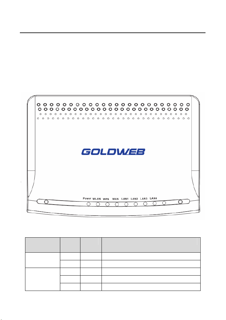
3.1 Front Panel and LED Status
There are 8 LED indicators on the front panel of the wireless router. By observing
their status, you can judge whether the device runs normally.
The following table describes the status of LED indicators on the front panel.
LED
Indicator
WLAN
Color Status Description
Green On Power is on. Power
- Off Power is off or the device is down.
Green On Radio switch is turned on.
Green Blink Data is being transmitted.
- Off Radio switch is shut off.
5

GW-WR150N/GW-WR150ND 150Mbps Wireless Router User Manual
WPS
WAN
LAN1/LAN2/
LAN3/LAN4
Green On Connection succeeds under Wi-Fi
Protected Setup.
Green Blink Negotiation is in progress under Wi-Fi
Protected Setup.
- Off Wi-Fi Protected Setup is disabled.
Green On Connection succeeds.
Green Blink Data is being transmitted.
- Off No WAN connection.
Green On LAN connection succeeds.
Green Blink Data is being transmitted.
- Off No LAN connection.
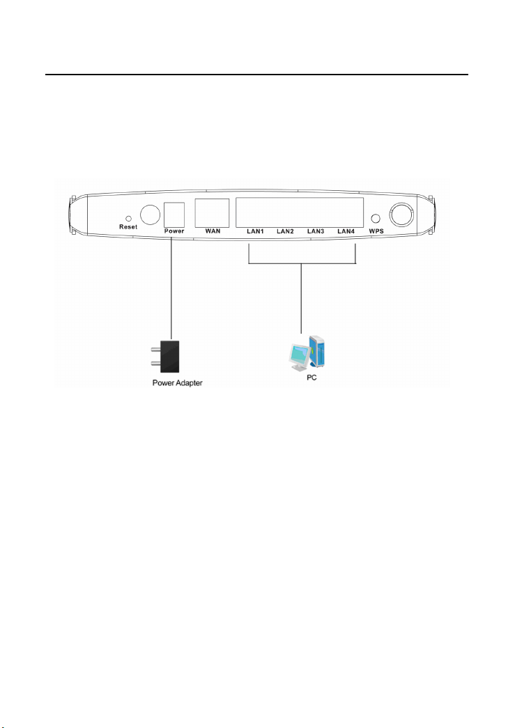
3.2 Rear Panel and Interface Description
The following table describes the interfaces or the buttons on the rear panel.
Interface/Button Description
Reset Press Reset gently for 3-6 seconds with a fine needle
inserted into the hole and then release the button. The
system reboots and returns to the factory defaults.
Power Power socket, for connecting the power adapter.
WAN WAN interface, for connecting WAN or the uplink
network devices.
LAN1/LAN2/
LAN3/LAN4
WPS This button is used for enabling WPS PBC mode. If
LAN interfaces, for connecting hub, switch, or
computer on LAN.
WPS is enabled, press this button, and then AP starts
to accept the negotiation of PBC mode.
6

GW-WR150N/GW-WR150ND 150Mbps Wireless Router User Manual
Note:
Do not press Reset unless you want to clear the current settings. The Reset button
is in a small circular hole on the rear panel. If you want to restore the default
settings, please press Reset gently for 3-6 seconds with a fine needle inserted into
the hole and then release the button. The system reboots and returns to the factory
default settings.
Warning:
The power specification is 12V, 500 mA. If the power adapter does not match the
specification, it may damage the device.
3.3 Hardware Installation
3.3.1 System Requirements
Before installing the device, please make sure that the following items are ready.
One Ethernet RJ45 cable (10Base-T/100Base-T)
One wireless router
A PC is already installed with the TCP/IP protocol and the PC can access
the Internet.
3.3.2 Before You Begin
Before you install the device, please pay attention to the following items:
When the device is connected to a computer, hub, router or switch, the
Ethernet cable should be less than 100 meters.
Do not place this device on an unstable surface or support. Do not put
this device on the ground.
Keep the device clean. Avoid the device from direct sunshine. Avoid any
metal in the device.
Place the device in the center of the area, and try to optimize the wireless
coverage.
7
GW-WR150N/GW-WR150ND 150Mbps Wireless Router User Manual
3.3.3 Connecting the Device
To connect the device, do as follows:
Step 1 Connect one end of the RJ45 cable to the AP’s LAN interface.
Step 2 Connect the other end of the RJ45 cable to your PC.
Step 3 Connect the power adapter to the AP’s power socket.
3.4 Operation Range
The operation range of AP depends on the actual environment. When the device is
placed in the house or in the office, the overall arrangements are different. So the
path and effect for signal transmission are different. For example, the outdoor
straight transmission distance for some devices in the open air is up to 150 meters,
and the indoor straight transmission distance is up to 100 meters.
3.5 Roaming
Suppose that several APs run in the same network. Each AP acts as one BSS, and
has its coverage range. One wireless client terminal (e.g. notebook PC or PDA) can
realize roaming from one AP to another AP correctly. In that case, the wireless
client terminal can communicate with the other devices within multiple APs’
coverage.
In order to realize the wireless client roaming among different APs, you need to set
8

GW-WR150N/GW-WR150ND 150Mbps Wireless Router User Manual
the APs properly. Do as follows:
Set the same SSID for different APs.
The SSIDs of all the computers and PDAs should be consistent with that of
APs.
All the BSSs must use the same wireless channel.
If the encryption function is enabled, all the APs should configure the same
encryption mode and the encryption key for establishing connection.
APs must keep the wireless signal covering the whole operation
environment and the wireless signal should be continuous. Please put the
APs to the appropriate places for a better network coverage.
9

GW-WR150N/GW-WR150ND 150Mbps Wireless Router User Manual
4 TCP/IP Settings and Wireless Connection
Introduction
Web management tool allows you to configure AP. The recommended browser is
Internet Explorer 5.0 version or above.
The following sections describe how to set the Internet connection, local Ethernet
connection, and wireless connection, and how to access the Web page.
4.1 TCP/IP Settings
By default, the IP address of LAN interface of is 192.168.1.1.The subnet mask is
255.255.255.0. The DHCP Server is enabled.
It is recommended you set the network adapter to be Obtain an IP address
automatically. Your PC acquires IP address, subnet mask, gateway, and DNS
address automatically via the AP. If you know the setting of the current LAN
interface, you can manually set the TCP/IP properties of the network adapter, so
that your PC can communicate with AP.
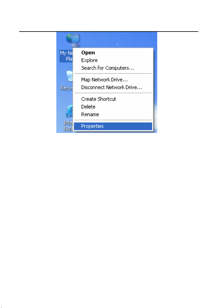
You may manually set the network adapter by following the steps below:
Step 1 Right-click the icon of My Network Places (for example, Windows XP)
and select Properties in the menu. The Network Connections page
appears.
10
GW-WR150N/GW-WR150ND 150Mbps Wireless Router User Manual
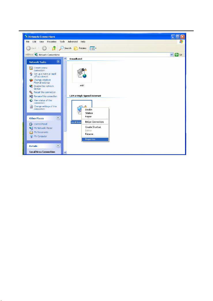
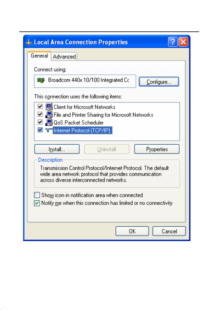
Step 2 Right-click the network adapter icon and choose Properties from the
menu. The Local Area Connections Properties appears. (Note: If there
are several network cards on your PC, it may not display the Local Area
Connections Properties page. It may display other dialog boxes.)
11
GW-WR150N/GW-WR150ND 150Mbps Wireless Router User Manual
Step 3 Double-click the Internet Protocol (TCP/IP) to display the Internet
Protocol (TCP/IP) Properties page.
12
GW-WR150N/GW-WR150ND 150Mbps Wireless Router User Manual
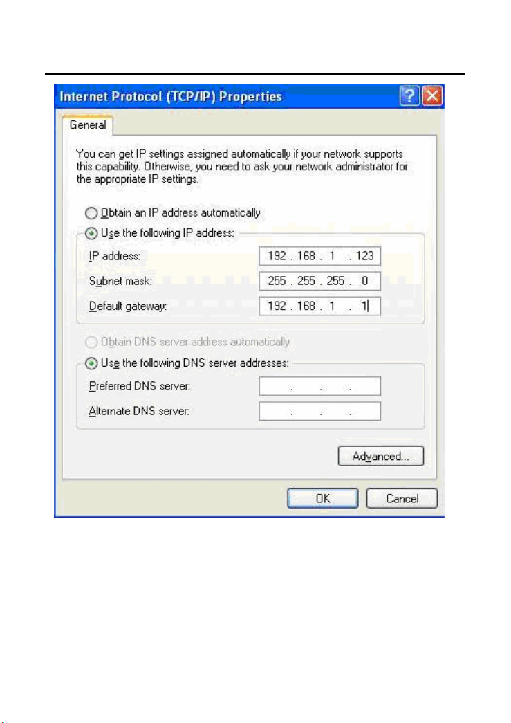
Step 4 Select Use the following IP address and enter the IP address of the
network adapter. The IP address should belong to the IP network
segment 192.168. 1.X (X is a digit between 2 and 254).
13
GW-WR150N/GW-WR150ND 150Mbps Wireless Router User Manual
Step 5 Set the subnet mask and then click OK to finish manual setting.
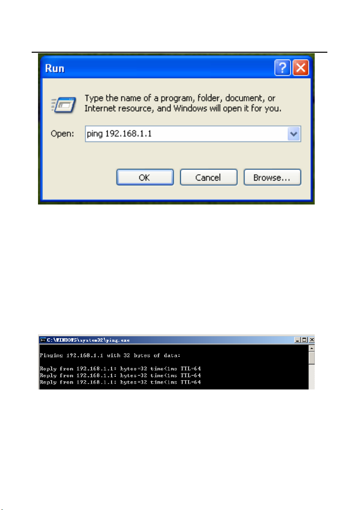
Step 6 After finishing setting, you may ping the default IP address of the AP, to
check whether the current connection between PC and the AP is normal.
Click RUN… on the lower left corner of desktop, and then enter ping
192.168.1.1 in the dialog box. See the following figure:
14
GW-WR150N/GW-WR150ND 150Mbps Wireless Router User Manual
Note:
192.168.1.1 is the default IP address of the LAN interface. If this IP address is
changed and you need to ping the IP address of AP, you should enter the current IP
address in the dialog box above.
Step 7 If PC can ping through the default IP address of AP, it indicates that the
connection between your PC and the AP is normal. See the following
figure:
4.2 Wireless Connection Introduction
15
GW-WR150N/GW-WR150ND 150Mbps Wireless Router User Manual
By default, the AP function of the wireless router is enabled. User that uses the
wireless network adapter can follow the steps below to finish the wireless
connection settings.
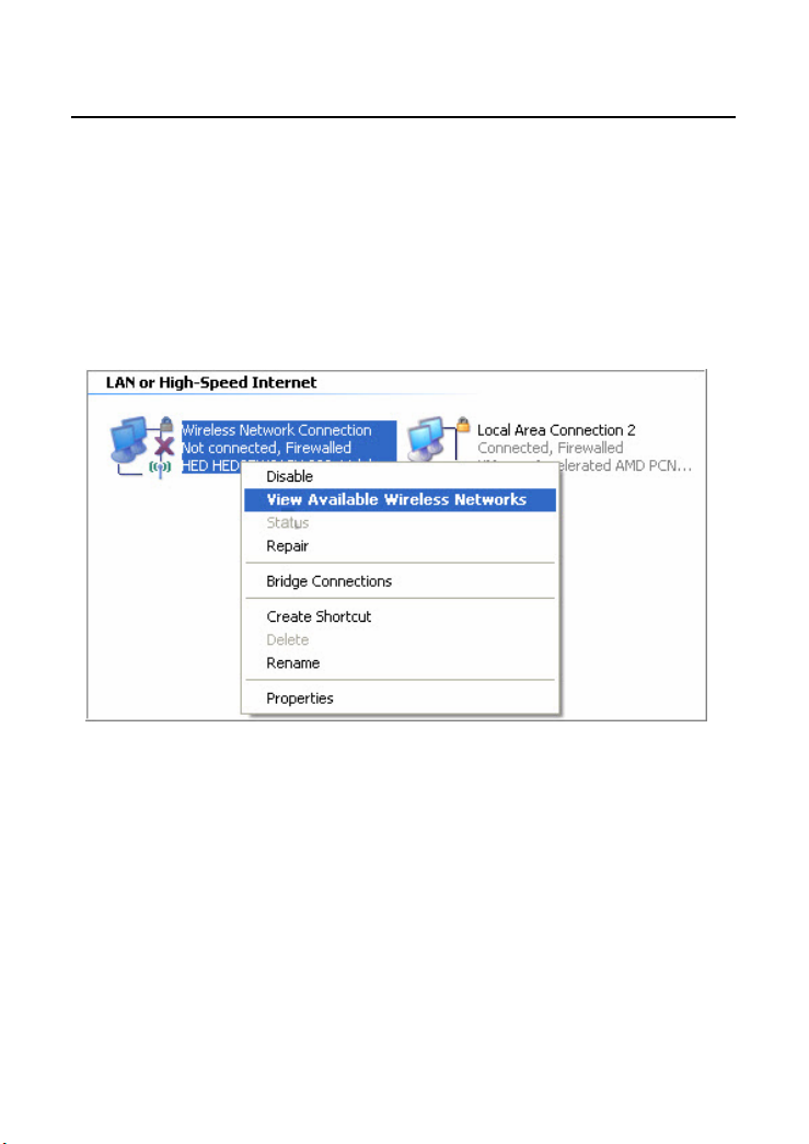
Step 1 Enable your wireless network adapter on your PC, and make sure that
the Wireless Zero Configuration tool is available. Right-click the
Wireless Network Connection icon and select View Available
Wireless Networks.
Step 2 In the Wireless Network Connection page, click Refresh network list
and the network list will be refreshed. The default SSID of the wireless
router is GOLDWEB_XXXXXX (“XXXXXX” is the end 6 digits of MAC
address). Choose the wireless router (e.g. GOLDWEB_B418A0) that you
want to connect, and then click the Connect button. The default wireless
security mode is Disable, and you can connect the wireless router
directly without entering an encryption key. If the wireless router is
16
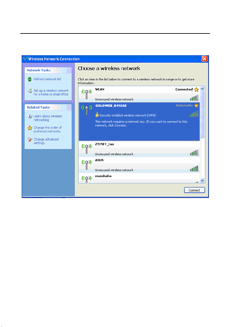
GW-WR150N/GW-WR150ND 150Mbps Wireless Router User Manual
encrypted, you need to enter the correct key to connect to the wireless
router.
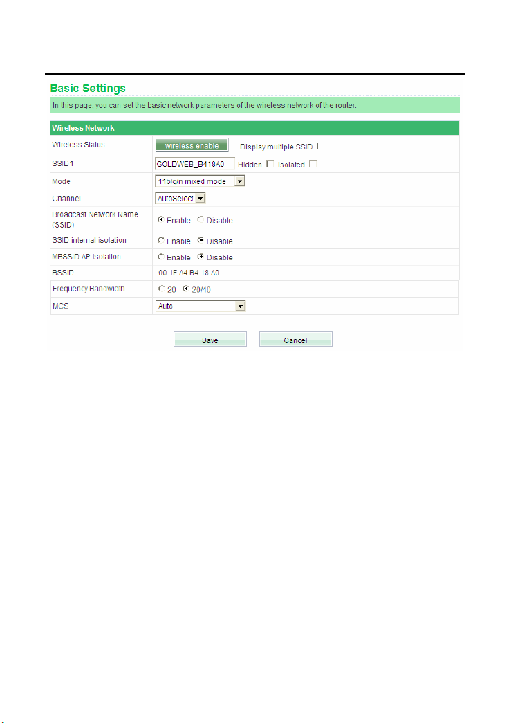
Step 3 If you are not sure of the available SSID, please log in to the router’s
Web page, and view the SSID in the Basic Settings page of the wireless
settings. For more information about the wireless settings, please refer to
6.4 Wireless Settings.
17
GW-WR150N/GW-WR150ND 150Mbps Wireless Router User Manual
Note:
After your wireless network card connects to the wireless router successfully,
usually, you should set the network adapter to be Obtain an IP address
automatically.
18
GW-WR150N/GW-WR150ND 150Mbps Wireless Router User Manual
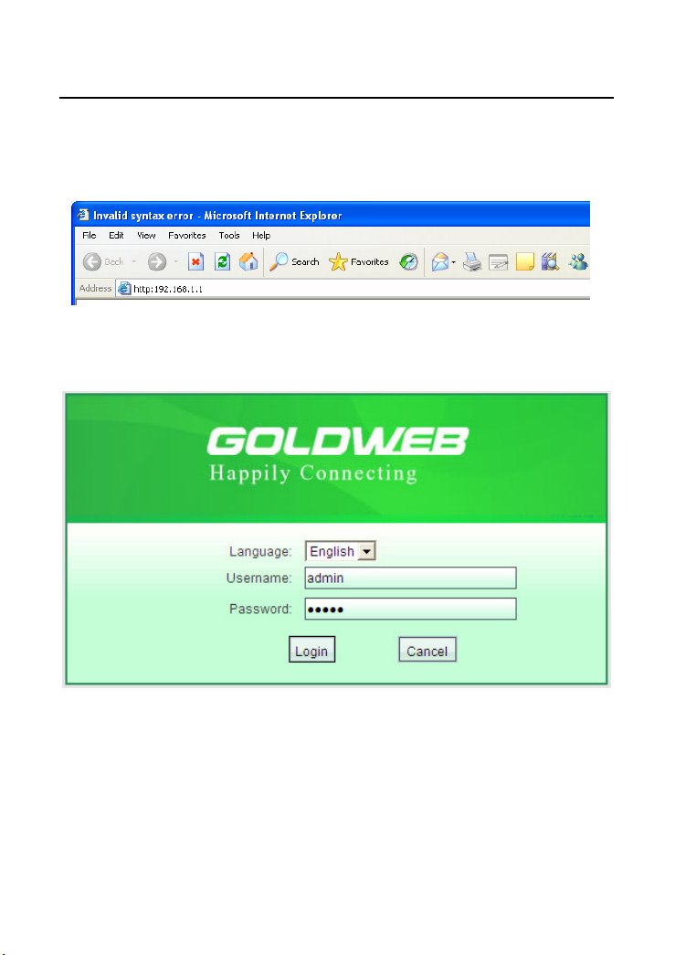
5 Logging In to the Web Page
Open the browser, and enter the http://192.168.1.1/ in the IE address bar.
Enter the user name (admin, by default) and the password (admin, by default) in
the login page.
After clicking Login in the login page, you can log in to the Web page of AP.
After logging in to the Web page, you can view, configure and modify the router
settings. In order to make the settings and changes take effect, sometimes, you
need to reboot the wireless router.
Caution:
19

GW-WR150N/GW-WR150ND 150Mbps Wireless Router User Manual
If you are managing the wireless router by Web pages, do not cut off the power
supply, otherwise, it may damage the device.
20
GW-WR150N/GW-WR150ND 150Mbps Wireless Router User Manual
6 Web Configuration
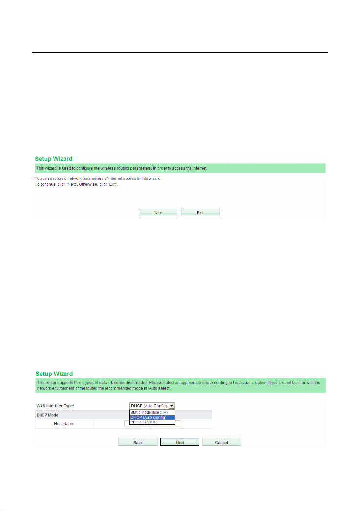
6.1 Setup Wizard
After logging in to the Web page, choose Setup Wizard on the left pane of the page
to display the Setup Wizard page.
You can set the basic network parameters for accessing the Internet by this wizard.
If you are not familiar with this product or do not have much network knowledge,
you can follow the on-screen instructions and complete the settings easily.
If you are an expert in wireless network, you can exit the wizard and set the
functions of the wireless router in the corresponding pages.
To continue, click Next.
To exit the wizard, click Exit.
After clicking Next, the following page appears.
21
GW-WR150N/GW-WR150ND 150Mbps Wireless Router User Manual
This page provides three types of WAN connection types, including Static Mode
(fixed IP), DHCP (Auto Config), and PPPoE (ADSL).
Note:
If you do not insert the network cable into the WAN interface of the wireless router,
the page above will not appear.
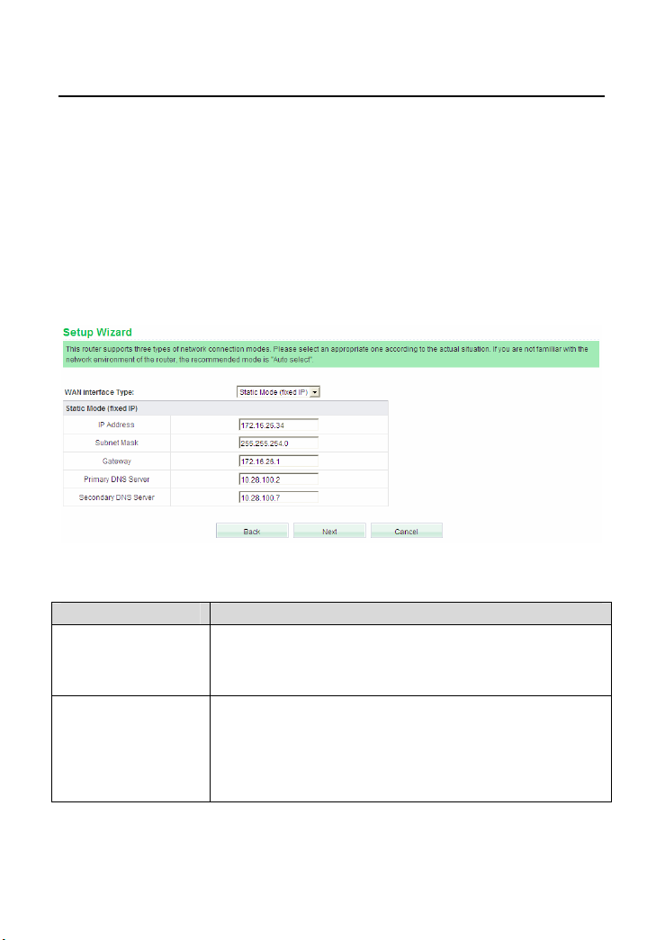
Static Mode (fixed IP)
If you select the Static Mode (fixed IP), the following page appears.
The parameters in this page are described as follows:
Field Description
IP Address
Enter the WAN IP address provided by the ISP. It is an
Subnet Mask
essential parameter, and you cannot leave it to be blank.
Enter the subnet mask provided by the ISP. The subnet
mask may vary according to the network types. Generally, it
is set to be 255.255.255.0 (C Cat.)
22
GW-WR150N/GW-WR150ND 150Mbps Wireless Router User Manual
Field Description
Gateway
Primary DNS Server The ISP usually provides at least one DNS address. If It
Secondary DNS
Server
Enter the gateway provided by the ISP.
provides two DNS addresses, enter one of them to the field
of Secondary DNS Server.
Enter the DNS server address provided by the ISP.
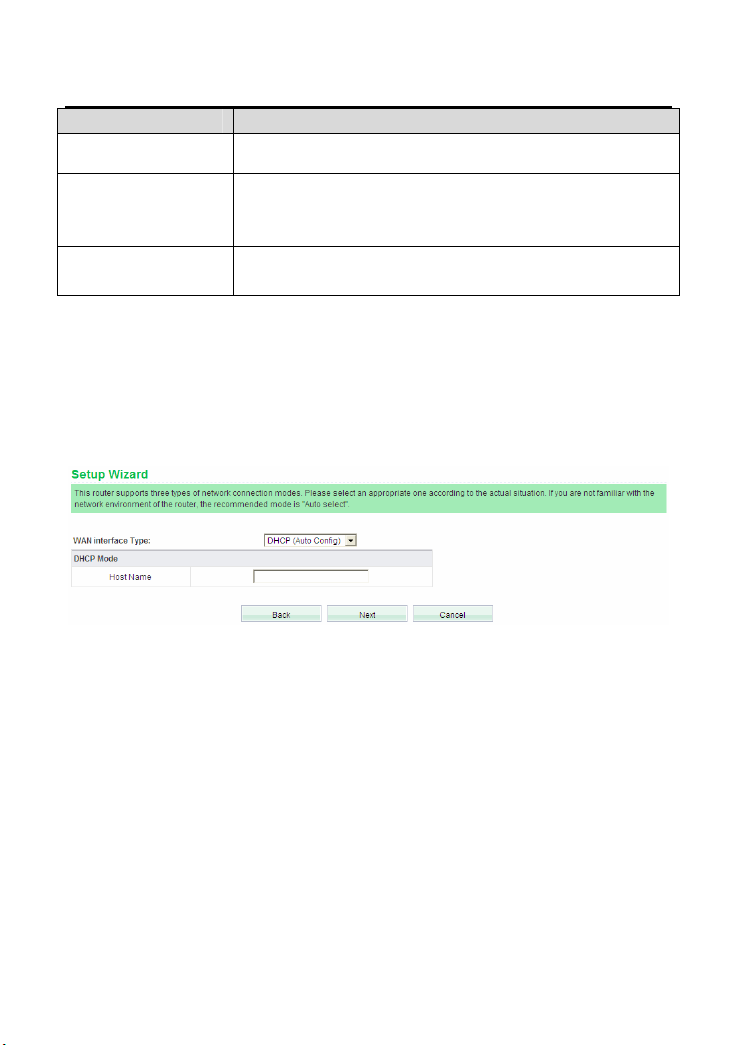
DHCP (Auto Config)
If you select the DHCP (Auto Config), the wireless router acquires the network
parameters via the WAN interface, such as the IP address, subnet mask, gateway,
and DNS server address.
Note:
In the Running Status page, you can view the network parameters assigned by the
DHCP server, such as the IP address, subnet mask, gateway, and DNS server
address.
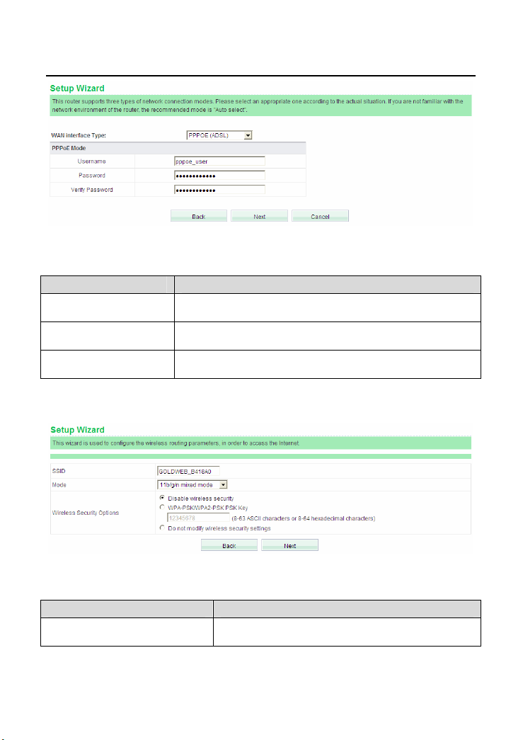
PPPoE (ADSL)
If you select the PPPoE (ADSL), the following page appears.
23
GW-WR150N/GW-WR150ND 150Mbps Wireless Router User Manual
The parameters in this page are described as follows:
Field Description
Username
Enter the user name provided by the ISP.
Password
Verify Password
After setting the WAN connection type, click Next to display the following page.
The parameters in this page are described as follows:
Field Description
SSID
Enter the password provided by the ISP.
Enter the password again.
The maximum character length for SSID is 32
24

GW-WR150N/GW-WR150ND 150Mbps Wireless Router User Manual
Field Description
characters. The legal characters include letter,
number, underline or the combination of these
characters.
Mode Select a proper network mode from the drop-down
list.
11b/g mixed mode
11b only
11g only
11b/g/n mixed mode (default)
Mode
Wireless Security Options
Disable Wireless Security: Enable or
disable the wireless security.
WPA-PSK/WPA2-PSK PSK Key: Enable
or disable the encryption function. When
selecting this option, you need to enter a
key in the field of WPA-PSK/WPA2-PSK
PSK Key. An encryption key should
consist of 8-63 ACSII characters or 8-64
hexadecimal characters.
Do not modify wireless security
settings: When selecting this option, the
wireless router will keep the previous
25
GW-WR150N/GW-WR150ND 150Mbps Wireless Router User Manual
Field Description
wireless security settings. If the wireless
security settings have never been
modified, after selecting this option, it will
keep the default wireless security settings.
Note:
All the characters on the keyboard are ASCII code. Hexadecimal characters include
the digits 0-9 and the letters such as A, B, C, and D.
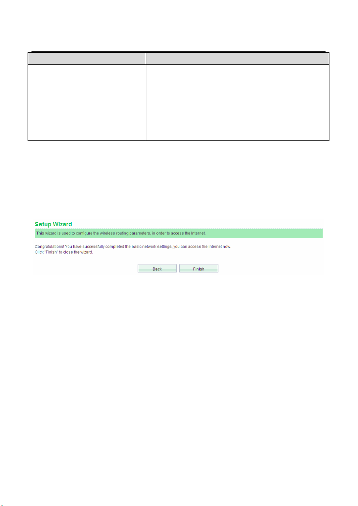
After finishing the wireless settings, click Next to display the following page.
Click Finish to complete the wizard settings.
6.2 Running Status
Choose Running Status to display the Running Status page.
26

GW-WR150N/GW-WR150ND 150Mbps Wireless Router User Manual
This page displays the information about current running status of the wireless
router, including the information about LAN, wireless, and WAN interfaces, and the
statistical information of the WAN interface.
6.3 Network Settings
In the Router mode, the following figure shows the submenus of the Network
Settings:
27

GW-WR150N/GW-WR150ND 150Mbps Wireless Router User Manual
The submenus of Network Settings include Operating Mode, LAN Interface
Settings, WAN Interface Settings and MAC Address Cloning.
6.3.1 Operating Mode
Choose Operating Mode to display the Operating Mode page.
The AP provides two types of operation modes, including Bridge and Router.
The parameters in this page are described as follows:
Mode Description
Bridge In the Bridge mode, the AP acts as a hub.
Router In the Router mode, the AP allows routing between WAN and
LAN, or WAN and wireless network.
NAT
Enabled
This function can only be used only in the Router mode. After
NAT is enabled, the device can provide address translation
28

GW-WR150N/GW-WR150ND 150Mbps Wireless Router User Manual
Mode Description
between the interior network and the exterior network for LAN
and wireless network.
After finishing setting, click Save to save the settings.
6.3.2 LAN Interface Settings
Choose Network Settings > LAN Interface Settings to display the LAN Interface
Settings page.
In this page, you are allowed to configure the parameters of the LAN interface. If
necessary, you can change the IP address of the LAN interface according to the
actual network environment.
The parameters in this page are described as follows:
Field Description
MAC Address
IP Address
Display the MAC address of the LAN interface. It cannot be
changed.
The IP address for the LAN user to access the wireless router.
The default value is 192.168.1.1. You can change it if
necessary.
29

GW-WR150N/GW-WR150ND 150Mbps Wireless Router User Manual
Field Description
The subnet mask that the wireless router provides to the LAN
Subnet Mask
After finishing setting, click Save to save the settings.
Note:
user. You can enter a different subnet mask according to the
actual network status.
If you have changed the IP address of the LAN interface, you need to enter
the new IP address to log in to the Web page, and the default gateways of
all the hosts in LAN must be set to be the new IP address, for accessing the
Internet.
The subnet masks of all the hosts in LAN must be set to be the same as the
subnet mask in this page.
6.3.3 WAN Interface Settings
Choose Network Settings > WAN Interface Settings to display the WAN
Interface Settings page.
30

GW-WR150N/GW-WR150ND 150Mbps Wireless Router User Manual
This page is used to configure the WAN connection parameters. This page provides
4 types of WAN interface connection types, including Dynamic IP (DHCP), Static
IP, PPPoE, and DHCP+. In this page, you may choose the proper WAN interface
connection type and configure the parameters related to the connection type.
z Dynamic IP (DHCP)
If you select Dynamic IP (DHCP), the wireless router acquires the network
parameters via the WAN interface, such as the IP address, subnet mask, and
gateway. If the ISP does not provide any network parameter, please select this
WAN interface connection type.
31

GW-WR150N/GW-WR150ND 150Mbps Wireless Router User Manual
The parameters in this page are described as follows:
Field Description
WAN Interface
Connection Type
IP Address Display the IP address assigned by the DHCP server.
Subnet Mask Display the subnet mask assigned by the DHCP server.
Gateway Display the gateway assigned by the DHCP server.
Packet MTU
(byte)
Manually set the
DNS server
DNS Server
Secondary DNS
Server
Select Dynamic IP (DHCP) in the drop-down list.
The default value of MTU (Maximum Transmission Unit) is
1500. Usually, do not change the MTU value. You may consult
your ISP whether this value needs to be modified.
Whether to manually set the DNS server.
Displays the DNS server address provided by the ISP. After
enabling Manually set the DNS server, you may set at least
one DNS server. When connecting, the wireless router will
adopt the DNS server that is set manually first.
Displays the DNS server address provided by the ISP. After
enabling Manually set the DNS server, you may enter the
second DNS server if necessary.
32

GW-WR150N/GW-WR150ND 150Mbps Wireless Router User Manual
After finishing setting, click Save to save the settings.
Static IP
If the ISP provides the information of the WAN interface, please select the Static IP
connection type. If you are not sure of the detailed settings, please consult your
ISP.
The parameters in this page are described as follows:
Field Description
WAN Interface
Connection Type
IP Address Enter the WAN IP address provided by the ISP. You are not
Subnet Mask Enter the WAN subnet mask provided by the ISP. The subnet
Gateway Enter the gateway provided by the ISP. It is the IP address for
Select Static IP from the drop-down list.
allowed to leave it to be blank.
mask may vary according to the network types. Generally, it is
set to be 255.255.255.0 (C Cat.)
connecting the ISP.
33

GW-WR150N/GW-WR150ND 150Mbps Wireless Router User Manual
Field Description
Packet MTU
(byte)
DNS Server The ISP usually provides at least one DNS address. If It
Secondary DNS
Server
After finishing setting, click Save to save the settings.
z PPPoE
If the ISP provides the PPPoE connection type, it also provides the username and
the password for you to access the Internet.
The default value of MTU (Maximum Transmission Unit) is
1500. Usually, do not change the MTU value. You may consult
your ISP whether this value needs to be modified.
provides two DNS addresses, enter one of them to the field of
Secondary DNS Server.
Enter the DNS server address provided by the ISP.
34

GW-WR150N/GW-WR150ND 150Mbps Wireless Router User Manual
The parameters in this page are described as follows:
Field Description
WAN Interface
Connection Type
Username
Select PPPoE from the drop-down list.
Enter the user name provided by the ISP.
Password
Service Name Specify the PPPoE server name if there are multiple
Enter the password provided by the ISP.
PPPoE servers. It is optional.
35

GW-WR150N/GW-WR150ND 150Mbps Wireless Router User Manual
Field Description
Receive ISP's DNS/
Manually enter DNS
DNS Server Enter the DNS server address.
Secondary DNS Server Enter the DNS server address. (Optional)
Packet (MTU) (byte) The default value of MTU (Maximum Transmission Unit)
Select the appropriate
connection mode as
required:
Receive ISP's DNS: Enable or disable this function.
After enabling this function, the wireless router
automatically acquires the DNS server address by
the ISP.
Manually enter DNS: Enable or disable this
function. After enabling this function, you need to
enter at least one DNS address.
is 1500. It is recommended to keep the default MTU
value. You may consult your ISP whether this value
needs to be modified.
The wireless router provides 3 types of connection
modes.
Connect on Demand: After selecting this option,
when there is a network access request from LAN,
system automatically establishes the network
connection. If there is no any network request from
LAN during Auto Disconnect Waiting Time,
system will automatically disconnect the connection.
For the users who pay the network fee according to
the on-line time, it is recommended you had better
adopt this connection mode, and it can help you to
reduce your network fee.
Auto: When selecting Auto, system automatically
establishes the connection after startup. In the
process of operating the wireless router, the network
connection will be disconnected for some external
reasons, and then system will try to establish the
connection every other interval (e.g. 10s) until the
connection succeeds. If your network service is
36

GW-WR150N/GW-WR150ND 150Mbps Wireless Router User Manual
Field Description
monthly payment, it is recommended you use this
connection mode.
Scheduled: When selecting Scheduled, you need
to set the Connection Period first. System will start
to establish the connection at the specified time and
end the connection at the specified end time.
Selecting this option can control the on-line time of
user in the internal network.
Auto Disconnect Waiting
Time
Need to support the
NetSniper
After finishing the settings, click Save to save the settings.
If there is no any network request from LAN during Auto
Disconnect Waiting Time, the system automatically
disconnects the connection for protecting your network
resources. The default value is 15 minutes. When the
value is set to be 0, it indicates that the connection will
not be automatically disconnected. You need to set this
parameter only in the Connect on Demand mode.
Enable or disable the NetSniper function.
The NetSniper can automatically detect the private proxy
server system or the illegal routers, and control their IP
packets.
DHCP+
If the ISP provides the DHCP+ connection type, it also provides the username and
the password for you to access the Internet.
37

GW-WR150N/GW-WR150ND 150Mbps Wireless Router User Manual
The parameters in this page are described as follows:
Field Description
WAN Interface
Connection Type
Username
Select DHCP+ from the drop-down list.
Enter the user name provided by the ISP.
Password
IP Address After the connection succeeds in the DHCP+ mode, this filed
Subnet Mask After the connection succeeds in the DHCP+ mode, this filed
Gateway After the connection succeeds in the DHCP+ mode, this filed
DNS
Server/Secondary
Enter the password provided by the ISP.
displays the IP address that is automatically acquired from the
DHCP server.
displays the subnet mask that is automatically acquired from
the ISP.
displays the gateway that is automatically acquired from the
ISP.
After the connection succeeds in the DHCP+ mode, this filed
displays the DNS server address that is automatically acquired
38

GW-WR150N/GW-WR150ND 150Mbps Wireless Router User Manual
Field Description
DNS Server from the ISP.
Packet (MTU)
(byte)
Authentication
Server
After finishing the settings, click Save to save the settings.
The default value of MTU (Maximum Transmission Unit) is
1500. Usually, do not change the MTU value. You may consult
your ISP whether this value needs to be modified.
Enter the authentication server address for accessing the
network provided by the ISP. If you are not sure of the
authentication server address, please consult your ISP.
6.3.4 MAC Address Cloning
Choose Network Settings > MAC Address Cloning to display the MAC Address
Cloning page.
This page is used to configure the WAN MAC address of the wireless router.
The parameters in this page are described as follows:
Field/Button Description
Enable Enable or disable the MAC address cloning.
MAC Address Display the MAC address of the WAN interface.
Some ISPs require user to bind the MAC address, and they
will provide a valid MAC address for user. In that case, you
need to enter the MAC address in this field. Do not change the
39

GW-WR150N/GW-WR150ND 150Mbps Wireless Router User Manual
Field/Button Description
MAC address, unless the ISP requires you to do so.
Fill my MAC
address
Click this button to clone the host MAC address to the field of
MAC Address. Do not clone the MAC address, unless the
ISP requires you to do so.
After finishing the settings, click the Save button to save the settings.
Note:
The MAC cloning function is only for the hosts in the LAN.
6.4 Wireless Settings
In the router mode, the following figure shows the submenus of the Wireless
Settings:
The submenu items of the Wireless Settings are Basic Settings, Wireless
40

GW-WR150N/GW-WR150ND 150Mbps Wireless Router User Manual
Security Settings, Wireless MAC Address Filter, Advanced Wireless Settings,
Wireless Client List, WPS Settings, and WDS Settings.
6.4.1 Basic Settings
Choose Wireless Settings > Basic Settings to display the Basic Settings page.
This page is used to configure the wireless basic parameters.
The parameters in this page are described as follows:
Field Description
41

GW-WR150N/GW-WR150ND 150Mbps Wireless Router User Manual
Field Description
Wireless Status Enable or disable the wireless function.
Display multiple
SSID
SSID1-4 The maximum entry length of SSID is 32-character. The legal
Mode Select a proper network mode from the drop-down list.
Channel Select a proper channel from the drop-down list. The default
Broadcast Network
Name (SSID)
SSID internal
isolation
MBSSID AP
Isolation
BSSID Display the MAC address of the wireless interface.
Frequency
Bandwidth
MCS You may select the MCS value from 0 to 7. The default MCS
If it is selected, all SSIDs fields are displayed. If it is not
selected, only SSID1 is displayed.
characters include letter, number, underline or the
combination of these characters. The default SSID is
NEXUS. You can select to enable, hide, or isolate an SSID by
selecting the corresponding check box next to the specific
SSID.
11b/g mixed mode
11b only
11g only
11b/g/n mixed mode (default)
channel is AutoSelect.
Whether to broadcast SSID. After enabling this function, the
wireless router will broadcast its SSID, and the wireless client
can scan the SSID.
Enable or disable the isolation among AP clients. If this
function is enabled, the client terminals that connect to the
same AP cannot communicate with each other.
Enable or disable the isolation among different SSIDs. After
enabling this function, the client terminals with different
SSIDs can not communicate with each other.
You may select 20 or 20/40.
is Auto.
42

GW-WR150N/GW-WR150ND 150Mbps Wireless Router User Manual
After finishing the settings, click the Save button to save the settings.
6.4.2 Wireless Security Settings
Choose Wireless Settings > Wireless Security Settings to display the Wireless
Security Settings page.
This page allows you to configure the wireless security modes and set the
encryption keys, to prevent unauthorized access and monitoring.
Select SSID
SSID: Select a SSID that you want to configure.
43

GW-WR150N/GW-WR150ND 150Mbps Wireless Router User Manual
Security Mode
This page provides 10 types of security modes, including Open, Shared,
WEPAUTO, WPA-Enterprise, WPA-PSK, WPA2-Enterprise, WPA2-PSK,
WPA-PSK/WPA2-PSK, WPA/WPA2-Enterprise, and Dynamic WEP 802.1X.
- Open Mode
The parameters of Open mode are described as follows:
Field Description
Security
Mode
Default Key Select a key as the default key.
WEP Keys
(WEP
Key1/2/3/4)
Select the Open mode in the drop-down list.
Set 64-bit or 128-bit key. The key format is Hex or ASCII.
Note:
When selecting the Hex format, you need to set 5-bit or 13-bit hex characters as the
WEP key. Hex characters include the digits (0-9), and the letters (A-Z). When
selecting the ASCII format, the WEP key should be set to be 10-bit or 26-bit ASCII
44

GW-WR150N/GW-WR150ND 150Mbps Wireless Router User Manual
characters.
- Shared Mode
The parameters of Shared mode are described as follows:
Field Description
Security
Mode
Default Key Select a key as the default key.
WEP Keys
(WEP
Key1/2/3/4)
Select the Shared mode in the drop-down list. The
Shared mode only supports WEP.
Set 64-bit or 128-bit key. The key format is Hex or ASCII.
- WEPAUTO Mode
45

GW-WR150N/GW-WR150ND 150Mbps Wireless Router User Manual
The parameter description of WEPAUTO mode, please refer to the Open mode.
- WPA-Enterprise Mode
The parameters of WPA-Enterprise mode are described as follows:
Field Description
Security
Mode
Select the WPA-Enterprise in the drop-down list.
46

GW-WR150N/GW-WR150ND 150Mbps Wireless Router User Manual
Field Description
WPA
Algorithms
Key
Renewal
Interval
IP Address Enter the IP address of the RADIUS server. RADIUS
Port The port number that the RADIUS server uses. The
Shared
Secret
Session
Timeout
Idle Timeout Set the idle timeout.
You may select TKIP or AES.
Set the key renewal interval. The value 0 indicates that
system does not renew the key.
server is used to authenticate the hosts in the wireless
network.
default port number is 1812. You may change it according
to the server setting.
Set the shared key for accessing the RADIUS server.
If this value is 0, it indicates that there is no session time
limit.
- WPA-PSK Mode
The parameters of WPA-PSK mode are described as follows:
Field Description
Security Select the WPA-PSK mode in the drop-down list.
47

GW-WR150N/GW-WR150ND 150Mbps Wireless Router User Manual
Field Description
Mode
WPA
Algorithms
Pass
Phrase
Key
Renewal
Interval
Select TKIP or AES.
Set 8-bit to 64-bit key in ASCII characters.
Set the key renewal interval. The value 0 indicates that
system does not renew the key.
- WPA2-Enterprise Mode
The parameters of WPA2-Enterprise mode are described as follows:
Field Description
Security Mode Select theWPA2-Enterprise in the drop-down list.
WPA Algorithms You may select TKIP, AES, or TKIP+AES.
Key Renewal Set the key renewal interval. The value 0 indicates
48

GW-WR150N/GW-WR150ND 150Mbps Wireless Router User Manual
Field Description
Interval that system does not renew the key.
PMK Cache
Period
Pre-Authentication Enable or disable pre-authentication.
IP Address Enter the IP address of the RADIUS server. RADIUS
Port The port number that the RADIUS server uses. The
Shared Secret Set the shared key for accessing the RADIUS
Session Timeout If this value is 0, it indicates that there is no session
Idle Timeout Set the idle timeout.
Set the PMK (Pairwise Master Key) cache period.
PMK scheme allows the roaming users that pass
through the 802.11X/EAP handshake protocol to
roam to the previous AP again. PMK can decrease
the roaming delay and improve the roaming speed.
server is used to authenticate the hosts in the
wireless network.
default port number is 1812. You may change it
according to the server setting.
server.
time limit.
- WPA2-PSK Mode
The parameters of WPA2-PSK mode are described as follows:
49

GW-WR150N/GW-WR150ND 150Mbps Wireless Router User Manual
Field Description
Security
Mode
WPA
Algorithms
Pass Phrase Set 8-bit to 64-bit key in ASCII characters.
Key Renewal
Interval
Select the WPA2-PSK in the drop-down list.
You may select TKIP, AES, or TKIP+AES.
Set the key renewal interval. The value 0 indicates that
system does not renew the key.
- WPA-PSK/WPA2-PSK Mode
The parameter description of WPA-PSK/WPA2-PSK mode, please refer to the
WPA2-PSK mode.
- WPA/WPA2-Enterprise Mode
50

GW-WR150N/GW-WR150ND 150Mbps Wireless Router User Manual
The parameters of WPA/WPA2-Enterprise mode are described as follows:
Field Description
Security Mode Select the WPA/WPA2-Enterprise in the drop-down
list.
WPA Algorithms You may select TKIP, AES, or TKIP+AES.
Key Renewal
Interval
IP Address Enter the IP address of the RADIUS server. RADIUS
Port The port number that the RADIUS server uses. The
Shared Secret Set the shared key for accessing the RADIUS
Session Timeout If this value is 0, it indicates that there is no session
Idle Timeout Set the idle timeout.
Set the key renewal interval. The value 0 indicates
that system does not renew the key.
server is used to authenticate the hosts in the
wireless network.
default port number is 1812. You may change it
according to the server setting.
server.
time limit.
51

GW-WR150N/GW-WR150ND 150Mbps Wireless Router User Manual
- Dynamic WEP 802.1X
The parameters of Dynamic WEP 802.1X mode are described as follows:
Field Description
Security Mode Select the Dynamic WEP 802.1X in the drop-down
list.
IP Address Enter the IP address of the RADIUS server. RADIUS
server is used to authenticate the hosts in the
wireless network.
Port The port number that the RADIUS server uses. The
default port number is 1812. You may change it
according to the server setting.
Shared Secret Set the shared key for accessing the RADIUS
server.
Session Timeout If this value is 0, it indicates that there is no session
time limit.
Idle Timeout Set the idle timeout.
Note:
In order to connect to the wireless router successfully, the wireless settings (e.g.
52

GW-WR150N/GW-WR150ND 150Mbps Wireless Router User Manual
SSID) and the security settings (e.g. encryption key) of the hosts in the wireless
network should be consistent with that of the wireless router.
6.4.3 Wireless MAC Address Filter
The wireless MAC address filtering function is used to allow or reject the hosts in
the wireless network to access the WAN, for controlling the on-line permission of
the users in the wireless network.
Choose Wireless Settings > Wireless MAC Address Filter to display the
Wireless MAC Address Filtering page.
This page is used to allow or reject the wireless clients to access the wireless
network of the wireless router.
The parameters in this page are described as follows:
Field Description
Policy The filtering policies include Disable, Allow, and Reject.
Disable: Disable the wireless MAC address filtering
function.
Allow: Allow the wireless clients with the MAC addresses in
53

GW-WR150N/GW-WR150ND 150Mbps Wireless Router User Manual
Field Description
the MAC Address List to access the wireless network of
the wireless router.
Reject: Reject the wireless clients with the MAC addresses
in the MAC Address List to access the wireless network of
the wireless router.
Add MAC Add a MAC address of the wireless client.
After finishing the settings, click the Save button to save the settings.
6.4.4 Advanced Wireless Settings
Choose Wireless Settings > Advanced Wireless Settings to display the
Advanced Wireless Settings page.
54

GW-WR150N/GW-WR150ND 150Mbps Wireless Router User Manual
This page allows you to configure the advanced wireless settings.
Parameter Description
The parameters in this page are described as follows:
Field Description
BG Protection Mode
You may select On, Off, or Auto. The default BG protection
55

GW-WR150N/GW-WR150ND 150Mbps Wireless Router User Manual
Field Description
mode is Auto.
Beacon Interval
By default, wireless beacon signal sends data to station
every other 100 ms. The range is 20~999.
DTIM (Delivery Traffic
Indication Message)
Fragment Threshold
RTS Threshold
TX Power
The default DTIM is 1ms. The range is 1~255.
Set the fragmentation threshold. Packets larger than the
size set in this field will be fragmented. Too many data
packets will lower the wireless network performance. The
Fragment Threshold value should not be set too low. The
default value is 2346.
Set the RTS (Request to send threshold.) threshold. When
the packet size is large than the preset RTS size, the
wireless router will send a RTS to the destination station to
start negotiation. When receiving the RTS frame, the
wireless station will send back a CTS frame to the wireless
router, to indicate that they can communicate with each
other. The default value is 2347.
Set the Tx power of the wireless router. The default value is
100. The value 100 indicates full power.
Short Preamble Enable or disable short preamble. The default setting is
Disable.
Preamble defines the length of CRC correction block for the
56

GW-WR150N/GW-WR150ND 150Mbps Wireless Router User Manual
Field Description
wireless devices. Short preamble adopts 56-bit
synchronization field. The network whose network traffic is
dense should use shorter preambles.
Short Preamble is mainly applied to the efficiency
improvement of real- time applications, such as streaming
video, and Voice-Over-IP telephony.
Pkt_Aggregate Enable or disable the Pkt_Aggregate function.
Pkt_Aggregate can aggregate multiple data packets
together for improving the transmission efficiency.
DFS RDRegion
Set the register region. Different register regions limit the
ranges of different frequency.
WMM capable
APSD Capability
DLS Capable
WMM Parameters
Multicast-to-Unicast After enabling this function, the transmission quality of the
After finishing the settings, click the Save button to save the settings.
Enable or disable WMM. After enabling WMM, the wireless
router can process different types of wireless data according
to their priority levels.
Enable or disable APSD. After enabling APSD, it can
decrease the consumption of the power supply device.
Enable or disable DLS.
Click the WMM Configuration button to display the
configuration page of WMM parameters.
wireless multicast stream can be improved.
57

GW-WR150N/GW-WR150ND 150Mbps Wireless Router User Manual
Note:
The advanced wireless setting is only for advanced user. For the common user, do
not change any setting in this page.
WMM Configuration
- WMM Access Categories
At present, WMM defines traffic into 4 access categories.
AC_VO: Voice (highest priority)
AC_VI: Video (high priority)
AC_BE: Best effort (medium priority)
AC_BK: Background (low priority)
802.11 uses DCF (Distributed Coordination Function) scheme of the CSMA/CA
(Carrier Sense Multiple Access / Collision Avoidance) protocol to reduce the
chances of packets collision while one more devices access the wireless media at
the same time. A client wishing to transmit has to first listen to the channel for a
predetermined amount of time so as to check for any activity on the channel. If the
channel is sensed "idle", then the client is permitted to transmit. If the channel is
sensed as "busy", the station has to defer its transmission. The random interval
provides a fair transmission chance for all the devices.
58

GW-WR150N/GW-WR150ND 150Mbps Wireless Router User Manual
When each priority queue waits for sending packets, it has to wait a fixed time
AIFSN and a random time CW. They define time values by multiple time slots. For
802.11b, its time slot is 20ms. The time slot of 802.11a and 802.11g is 9 ms. CW
insures the random delay time of DCF, so that the packets collision among the
devices with the same access category can be avoided. If collision occurs, CW is
doubled until it exceeds its maximum value. After every successful transmission,
CW returns to the minimum value.
The priority queue that succeeds in the competition of sending packets will acquire
Txop time to send packets. If the txop value is 0, it is limited to be a MSDC (MAC
Service Data Unit).
- Setting the WMM Parameters
Click the WMM Configuration button in the Advanced Wireless Settings page,
and the following page appears.
59

GW-WR150N/GW-WR150ND 150Mbps Wireless Router User Manual
In this page, you can configure the WMM parameters of access point and station.
Note:
The wireless router provides the standard WMM settings. If you want to modify the
parameters above, please refer to the WMM settings of your WMM products.
The parameters in this page are described as follows:
Field Description
Aifsn Aifsn (Arbitrary Inter-Frame Space Number). This
parameter influences the delay time of WMM access
category. If you use voice or video service, you’d
better set this parameter to be smaller in the fields of
AC_VI and AC_VO. If it is E-mail or Web service,
you should set a bigger value in the fields of AC_BE
and AC_BK.
Cwmin Cwmin (Mini. Contention Window) also influences
the delay time of WMM access category. The
difference between AC_VI and AC_VO should be
smaller, but the difference between AC_BE and
AC_BK should be bigger.
Cwmax Cwmax (Max.Contention Window)
Txop Txop (Opportunity to Transmit) may optimize the
WMM access. Compared to the WMM access that
needs a higher priority, such as AC_VI and AC_VO,
this value should be bigger.
ACM ACM (Admission Control Mandatory) parameter
only reacts on AC_VI and AC_VO. If you set this
value to be 0, it indicates that AP is in the charge of
the access commands. If this value is 1, it means
the client is in the charge of the access commands.
Ackpolicy When WMM packets are transmitting, AP will
receive an echo request. If you set this value is 0, it
60

GW-WR150N/GW-WR150ND 150Mbps Wireless Router User Manual
Field Description
means AP does not send back an echo request,
which will bring positive effect for WMM. If this value
is 1, AP generates the response to the request.
Note:
Usually, you do not need to modify the WMM parameters.
DLS (Direct Link Setup) Configuration
The wireless router provides DLS function. Suppose that there are two WMM
devices. Enter the MAC address of a WMM device in the DLS setting of the other
device, and then connect the two WMM devices to the wireless router. In this way,
these two WMM devices can transmit message directly.
If you want to configure WMM DLS, do as follows:
Step1 Prepare two wireless network cards (A and B) and one wireless router.
Step2 Enable the DLS function in the Advanced Wireless Settings page of the
wireless router.
61

GW-WR150N/GW-WR150ND 150Mbps Wireless Router User Manual
Step3 Enable the DLS function of wireless network cards. Enter the MAC
address of wireless card A in the WMM page of the wireless network card
B, and then click the Apply button.
62

GW-WR150N/GW-WR150ND 150Mbps Wireless Router User Manual
Step4 If DLS succeeds, you can view the MAC address of wireless card A in the
WMM page of wireless card B, and vice versa.
6.4.5 Wireless Client List
Choose Wireless Settings > Wireless Client List to display the Wireless Client
List page.
63

GW-WR150N/GW-WR150ND 150Mbps Wireless Router User Manual
In this page, you can view the information of the clients that access the wireless
router.
6.4.6 WPS Settings
Choose Wireless Settings > WPS Settings to display the Wi-Fi Protected Setup
(WPS) page.
64

GW-WR150N/GW-WR150ND 150Mbps Wireless Router User Manual
In this page, you can configure the WPS settings.
WPS Settings Configuration
65

GW-WR150N/GW-WR150ND 150Mbps Wireless Router User Manual
WPS settings: Enable or disable the WPS.
After enabling WPS, you can configure the parameters related to WPS.
WPS Settings List
WPS settings list displays the preset WPS information, such as WPS current status,
WPS authentication mode, and WPS encryption type.
Click the OOB button in the Wi-Fi Protected Setup (WPS) page, system displays
the WPS default settings. See the following figure:
66

GW-WR150N/GW-WR150ND 150Mbps Wireless Router User Manual
WPS Mode Settings
WPS modes include PIN and PBC. For more details, please refer to WPS
Application.
WPS Setting Status
The figure above displays WPS current status.
WPS Application
This page provides two WPS modes, including PIN and PBC modes.
At present, WPS supports three types of operation modes, including Enrollee
mode, Registrar mode, and PBC mode. Enrollee and Registrar modes need to
apply PIN code negotiation.
- Enrollee Mode
Step 1 Select the enrollee mode on the wireless client, the software of wireless
client will generate a random PIN code, for example, 12345678.
Step 2 In the Wi-Fi Protected Setup (WPS) page, enter the PIN code of wireless
client, for example, 12345678.
Step 3 Click the Save button in the Wi-Fi Protected Setup (WPS) page to
submit the setting.
67

GW-WR150N/GW-WR150ND 150Mbps Wireless Router User Manual
- Registrar Mode
Step 1 View the AP PIN in the Wi-Fi Protected Setup (WPS) page, for example,
31668729.
Step 2 Select the Registrar mode on the wireless client and enter the PIN code
of the wireless router. See the following figure:
68

GW-WR150N/GW-WR150ND 150Mbps Wireless Router User Manual
- PBC Mode
Step 1 In the Wi-Fi Protected Setup (WPS) page, select the PBC mode, and
then click the Save button. You may press the WPS button on the rear
panel.
Step 2 Enable the PBC function on the wireless client. In that case, the wireless
router and wireless client will automatically establish connection.
6.4.7 WDS Settings
Wireless Distribution System (WDS) is a system that enables the wireless
interconnection of access points in an IEEE 802.11 network. It allows a wireless
network to be expanded using multiple access points without the need for a wired
backbone to link them, as is traditionally required. The notable advantage of WDS
over other solutions is that it preserves the MAC addresses of client packets across
links between access points.
Choose Wireless Settings > WDS Settings to display the Wireless Distribution
69

GW-WR150N/GW-WR150ND 150Mbps Wireless Router User Manual
System (WDS) page.
This page provides three types of WDS modes, including Lazy Mode, Bridge
Mode, and Repeater Mode. You may also disable WDS.
Lazy Mode
- Parameter Description
70

GW-WR150N/GW-WR150ND 150Mbps Wireless Router User Manual
The parameters of Lazy Mode are described as follows:
Field Description
WDS Mode Select the Lazy Mode in the drop-down list.
Entity Model The physical modes in the drop-down list include CCK,
OFDM, and HTMIX
Encryption
Type
Encryption
Key
The encryption types you can select include NONE, WEP
64bits, WEP 128bits, WPA-PSK (TKIP), and WPA2-PSK
(AES).
Set the encryption key.
71

GW-WR150N/GW-WR150ND 150Mbps Wireless Router User Manual
Lazy Mode Configuration
In the lazy mode, the wireless router automatically connects to the WDS devices
that use the same SSID, channel, encryption mode, and the physical mode. You do
not need to manually enter other MAC addresses of the peer routers.
To configure the Lazy Mode, do as follows:
Step 1 In the Wireless Distribution System (WDS) page, set the WDS mode to
be Lazy Mode, and set the entity model and encryption type to accord
with the peer router (A router that needs to connect to the this wireless
router by WDS). After finishing the settings, click the Save button to save
the settings. The wireless router will work in the Lazy mode.
Step 2 Enter the Wireless Security Settings page, and set the security mode
of the wireless router to accord with the peer router.
Bridge Mode
- Parameter Description
72

GW-WR150N/GW-WR150ND 150Mbps Wireless Router User Manual
The parameters of Bridge Mode are described as follows:
Field Description
WDS Mode Select the Bridge Mode in the drop-down list.
Entity Model The physical modes in the drop-down list include CCK,
OFDM, and HTMIX.
73

GW-WR150N/GW-WR150ND 150Mbps Wireless Router User Manual
Field Description
Encryption Type The encryption types you can select include NONE, WEP
64bits, WEP 128bits, WPA-PSK (TKIP), and WPA2-PSK
(AES).
Encryption Key Set the encryption key.
Wireless Access
Node MAC
Address
The MAC address of another wireless router that
connects to this wireless router by WDS.
- Bridge Mode Configuration
In the bridge mode, you can use the wireless router to connect to other routers, for
extending wireless coverage. Meanwhile, it can also decrease the working load of
the AP that accesses the Internet. In that case, the wireless card does not directly
communicate with the wireless device that accesses the Internet, but it directly
communicates with the wireless router.
Step 1 In the Wireless Distribution System (WDS) page, select the WDS mode
to be Bridge Mode. Set the entity model and encryption type to accord
with the peer router, and then enter the MAC address of the peer router.
After finishing the settings, click the save button to save the settings. The
wireless router will work in the Bridge mode.
Step 2 Choose Wireless Settings > Wireless Security Settings to display the
Wireless Security Settings page. Set the security mode of the wireless
router to accord with the peer router.
74

GW-WR150N/GW-WR150ND 150Mbps Wireless Router User Manual
Repeater Mode
- Parameter Description
75

GW-WR150N/GW-WR150ND 150Mbps Wireless Router User Manual
The parameter description of the Repeater Mode, please refer to the Bridge
Mode.
- Repeater Mode Configuration
In the Repeater mode, you can use the wireless router to connect to the primary
76

GW-WR150N/GW-WR150ND 150Mbps Wireless Router User Manual
router, for extending the wireless coverage.
Step 1 Choose Wireless Settings > Basic Settings to display the Basic
Settings page.
Step 2 In this page, set the channel of the wireless router to accord with the peer
router.
Step 3 In the Wireless Distribution System (WDS) page, set the WDS mode to
be Repeater Mode, set the entity model and encryption type to accord
with the peer router, and then enter the MAC address of the peer AP.
After finishing the settings, click the Save button to save the settings.
The wireless router will work in the Repeater mode.
Step 4 Choose Wireless Settings > Wireless Security Settings to display the
Wireless Security Settings page.
77

GW-WR150N/GW-WR150ND 150Mbps Wireless Router User Manual
Step 5 In this page, set the security mode of the wireless router to accord with
the peer router.
Note:
In the WDS mode, do not set any mixed modes, for example,
WPA-PSK/WPA2-PSK.
Note:
In the WDS mode, do not set any mixed modes, for example,
WPA-PSK/WPA2-PSK.
Do not set all the WDS APs to be Lazy Mode, please ensure that at least one WDS
AP acts as Root Bridge and enter the MAC address of the wireless router to the
other routers.
For better compatibility, please try to adopt the products with the same model to
connect to the wireless router.
Establishing a Network by WDS Bridge Mode
78

GW-WR150N/GW-WR150ND 150Mbps Wireless Router User Manual
The following description shows how to use the WDS bridge mode of two devices to
establish a network. You may add more devices to establish a network.
Suppose that there are two APs. One is AP1, and the other is AP2. Enable the
DHCP server of AP1 and AP2.
The following table shows the settings of AP1 and AP2.
- Configuring AP1
Step 1 Enter http://192.168.1.1 in the IE address bar, and then enter the user
name (by default, admin) and the password (by default, admin) to log in
to the Web page.
79

GW-WR150N/GW-WR150ND 150Mbps Wireless Router User Manual
Step 2 In the
Step 3 Choose wireless Settings > Basic Settings to display the Basic
Wireless Distribution System (WDS) page, set the WDS mode
to be Bridge Mode, and enter the MAC address of the AP2.
Settings page. In this page, set the SSID of AP1. AP1 and AP2 must
use the same SSID and channel.
80

GW-WR150N/GW-WR150ND 150Mbps Wireless Router User Manual
Step 4 Enter the Wireless Security Settings page, and disable the security
mode.
81

GW-WR150N/GW-WR150ND 150Mbps Wireless Router User Manual
Step 5 Choose Network Settings > LAN Interface Settings to display the
LAN Interface Settings page. Set the IP address of AP1 to be
192.168.1.1 and then click the Save button to save the settings.
- Configuring AP2
Step 1 Choose Network Settings > LAN Interface Settings to display the
LAN Interface Settings page. Set the IP address of AP2 to be
192.168.1.2.
82

GW-WR150N/GW-WR150ND 150Mbps Wireless Router User Manual
Step 2 In the Wireless Distribution System (WDS) page, set the WDS mode
to be the Bridge Mode and enter the MAC address of the AP1. Then
click the Save button to save the settings.
6.5 DHCP Server
The following figure shows the submenus of the DHCP Server.
83

GW-WR150N/GW-WR150ND 150Mbps Wireless Router User Manual
The submenus of the DHCP Server include DHCP Service, Static Address
Allocation, and DHCP client list.
6.5.1 DHCP Service
The built-in DHCP server can automatically assign the network parameters such as
the IP address, to the hosts in the LAN. User does not need to manually set the IP
address, subnet mask, gateway, and DNS server.
Choose DHCP Server > DHCP Service to display the DHCP Service page.
This page is used to configure the DHCP server.
84

GW-WR150N/GW-WR150ND 150Mbps Wireless Router User Manual
The parameters in this page are described as follows:
Field Description
DHCP Server Enable or disable the DHCP server. When disabling the DHCP
server, you do not need to set the other parameters in this
page.
Start Address of
Address Pool
End Address of
Address Pool
Lease Time The lease time is the valid time of the IP address that the DHCP
Gateway Enter the IP address of the LAN interface. The default gateway
Primary DNS
Server
Secondary DNS
Server
After finishing setting, click the Save button to save the settings.
Note:
If you want to use the DHCP function of the wireless router, you need to set the
Internet Protocol (TCP/IP) to be Obtain an IP address automatically.
The starting IP address that the DHCP server automatically
assigns to the hosts in the LAN.
The end IP address that the DHCP server automatically assigns
to the hosts in the LAN.
server assigns to the hosts. During the valid period of the IP
address, the DHSP server will not assign this IP address to
other hosts.
is 192.168.1.1. It is optional.
Enter the primary DNS server address (optional). If you are not
sure of the DNS server address, please consult your ISP.
Enter the Secondary DNS server address (optional). If you are
not sure of the DNS server address, please consult your ISP.
6.5.2 Static Address Allocation
The static address allocation function of the wireless router can reserve the static IP
addresses for the computers with the specific MAC addresses. When a computer
whose MAC address is in the allocation table of static address requests the DHCP
server for an IP address, the DHCP server assigns the reserved IP address to the
computer.
85

GW-WR150N/GW-WR150ND 150Mbps Wireless Router User Manual
Choose DHCP Server > Static Address Allocation to display the Static Address
Allocation page.
The paramters in this page are described as follows:
IP Address Set the IP address that is reserved for a
MAC Address Enter the MAC address of the host on
Filed Description
host on the LAN side.
the LAN side.
After finishing setting, click the Save button to save the settings.
6.5.3 DHCP Client List
Choose DHCP Server > DHCP Client list to display the DHCP Clients list page.
86

GW-WR150N/GW-WR150ND 150Mbps Wireless Router User Manual
In this page, you can view all the network information of the hosts assigned by the
DHCP server in the LAN, such as the host name, MAC address, and IP address.
Click the Refresh button to refresh the client list.
The parameters in this page are described as follows:
Field Description
Host Name
MAC Address
IP Address
Lease Time
Display the host name.
Display the MAC address of the host.
Display the IP address assigned by the DHCP server.
Display the lease time of the IP address. Before the lease time of
the IP address is over, the client software will automatically apply
for the lease time.
6.6 Forwarding Rule
The following figure shows the submenus of the Forwarding Rule.
87

GW-WR150N/GW-WR150ND 150Mbps Wireless Router User Manual
The submenus of the Forwarding Rule include Virtual Server, Port Triggering
Settings, DMZ Host, and UPnP Settings.
6.6.1 Virtual Server
Firewall can prevent unexpected traffic in the Internet from your host in the LAN. The
virtual server can create a channel that can pass through the firewall. In that case, the
host in the Internet can communicate with a host in your LAN within certain port
range.
Choose Forwarding Rule > Virtual Server to display the Virtual Server page.
88

GW-WR150N/GW-WR150ND 150Mbps Wireless Router User Manual
In this page, you are allowed to add or delete a virtual server.
The parameters of Virtual Server are described as follows:
Field Description
Virtual Server Setting Enable or disable the virtual server settings.
IP Address Enter the IP address of the host that provides
virtual service in the LAN.
Port Range Set the service port range that the wireless
router provides to the WAN. The WAN user
acquires the service via the port. The port
range format is “the starting port - the end
port”.
Protocol Select the protocol for the virtual service. You
may select TCP, UDP or TCP&UDP.
Comment Enter the comment about the virtual server.
After finishing setting, click the Save button to save the settings.
89

GW-WR150N/GW-WR150ND 150Mbps Wireless Router User Manual
6.6.2 Port Triggering Settings
Some applications need multiple connections, such as network game, video
conference, and IP phone. Because of firewall, these applications cannot work under
simple NAT mode, but port forwarding can realize that. When an application
generates a connection to the triggered port, all the corresponding ports will be
opened, for establishing connection and providing service.
Choose Forwarding Rule > Port Triggering Settings to display the Port
Triggering Settings page.
In this page, you are allowed to view the preset rules, add or delete a rule, and
enable or disable a selected rule.
Click the Increase the application of rules button to display the following page.
90

GW-WR150N/GW-WR150ND 150Mbps Wireless Router User Manual
The parameters in this page are described as follows:
Field Description
Application Name
It provides two options according to the
added rules.
91

GW-WR150N/GW-WR150ND 150Mbps Wireless Router User Manual
Field Description
Please select one of applications: If
you select one of applications in the
drop-down list, system will automatically
configure the Start Trigger Port, End
Trigger Port, Trigger Protocol and so
on.
Custom application name: if you
select this option, you need to manually
set the parameters such as the Start
Trigger Port, End Trigger Port, and
Open Ports Protocol.
Start Trigger Port
End Trigger Port
Trigger Protocol
A range of ports can be
opened from after Trigger
A range of ports can be
opened to after Trigger
Open ports Protocol
After finishing setting, click the Save/Apply button to save and apply the settings.
The start port number that LAN user uses to
trigger the open port.
The end port number that LAN user uses to
trigger the open port.
Select the application protocol. You may
select TCP/UDP, TCP, or UDP.
The start port number that is opened to
WAN.
The end port number that is opened to
WAN.
Select the proper protocol that is opened to
WAN. You may select TCP/UDP, TCP, or
UDP.
6.6.3 DMZ Host
DMZ allows all the ports of a PC in your LAN to be exposed to the Internet. Set the
IP address of the PC to be DMZ host, so that the DMZ host will not be blocked by
92

GW-WR150N/GW-WR150ND 150Mbps Wireless Router User Manual
firewall and the host can realize bidirectional limitless communication with the
Internet users and servers.
Choose Forwarding Rule > DMZ Host to display the DMZ Host page.
The parameters of DMZ Host are described as follows:
Field Description
DMZ Status Enable or disable the DMZ settings.
IP Address of the DMZ
Host
After finishing the settings, click the save button to save the settings.
Enter the IP address of the DMZ host.
6.6.4 UPnP Settings
The hosts can generate the request for port conversion via the UPnP (Universal
Plug and Play) protocol, so that the external hosts can access the resources on the
internal hosts. For example, MSN Messenger on Windows ME and Windows XP
systems can make use of the UPnP protocol to make the limited NAT function back
to normal when using audio and video call.
Choose Forwarding Rule > UPnP Settings to display the UPnP Settings page.
93

GW-WR150N/GW-WR150ND 150Mbps Wireless Router User Manual
This page is used to enable or disable the UPnP settings, view the preset the UPnP
rules, and delete the selected rules.
Note:
Only when the applications support UPnP protocol, can you use this function.
UPnP function needs operation system support such as Windows ME, Windows XP,
and Windows Vista, and application software support.
6.7 Security Options
The following figure shows the submenus of the Security Options.
The submenus of the Security Options include Security Settings, Advanced
Security Settings, LAN Web Management, and Remote Web Management.
94

GW-WR150N/GW-WR150ND 150Mbps Wireless Router User Manual
6.7.1 Security Settings
Choose Security Options > Security Settings to display the Security Settings
page.
In this page, you are allowed to set Stateful Packet Inspection (SPI), Virtual Private
Network (VPN), and Application Layer Gateway (ALG).
The parameters in this page are described as follows:
Field Description
Stateful Packet
Inspection (SPI)
When the SPI firewall is enabled, only the users in the internal
network generate the requests, and then the connection is
established. In addition, all the requests from the external network
will be rejected by the SPI firewall.
When the SPI firewall is disabled, all the requests form the internal
network and external network can generate the connections,
which will make the hosts in the internal network be exposed to
the external network. Therefore, disabling the SPI firewall will
cause the security problem.
It is recommended you enable the SPI firewall.
95

GW-WR150N/GW-WR150ND 150Mbps Wireless Router User Manual
Field Description
Virtual Private
Network (VPN)
Application
Layer Gateway
(ALG)
After finishing setting, click the Save button to save the settings.
VPN provides the secure communication method for the remote
computers via the WAN. If the hosts in the internal network need
to use the VPN protocols such as PPTP, L2TP, and IPSec to
connect to the remote VPN network, you should enable the
corresponding passthrough function.
ALG provides network address and port conversion for some
application layer protocols such as FTP, and SIP that adopt
“control/data” mode when passing through the NAT gateway. It is
recommended you enable the ALG functions.
6.7.2 Advanced Security Settings
The goal of DoS (Denial of service) attack is using a large quantity of illusive
information to exhaust the resources of the destination host. The destination host is
forced to process the illusive traffic, which affects the processing of the legal traffic. If
the DoS attack is from the multiple source addresses, it is also called DDoS
(Distribution Denial of service) attack. Generally, all the source addresses of the DoS
attack and DDoS attack are fraudulent.
Choose Security Options > Advanced Security Settings to display the Advanced
Security Settings page.
96
 Loading...