

Gold Vision GV1475 Schematic
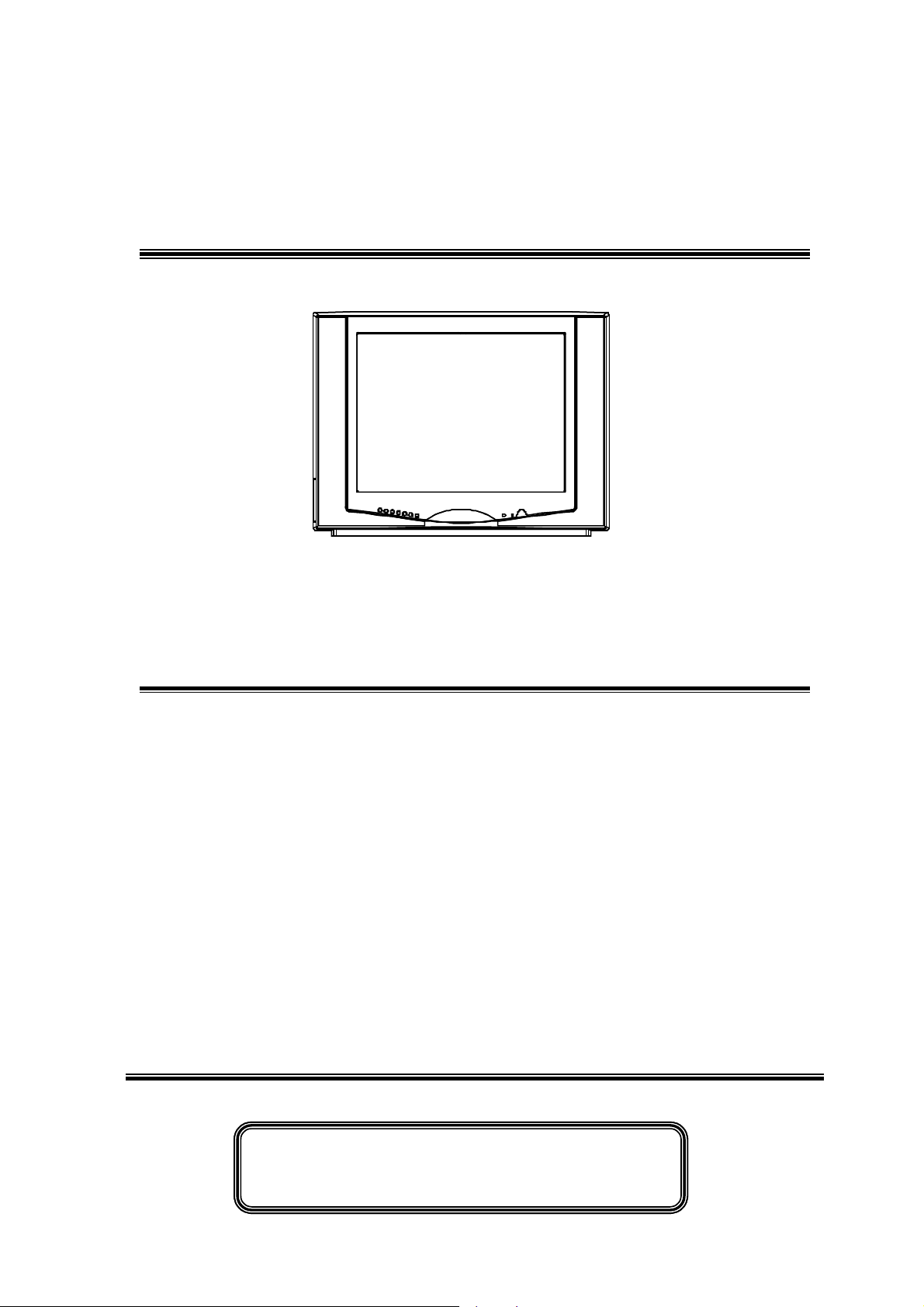
GOLD VISION
SERVICE MANUAL
T-GV-1475
1. Caution……………………………………………………………2
2. Specification………………………………………………………6
3. BOM List …………………………………………………………13
4. Alignment Procedure………………………………………….…35
5. Block Diagram……………………………………………………41
6. Schematic Diagram………………………………………………42
7. PCB Layout………….……………………………………………43
8. Exploded View Diagram …………………………………………44
This manual is the latest at the time of printing, and does not
include the modifi ca tio n w hich ma y b e made after the pri nti ng, by
the consta nt improvement of product.
CAUTION:
Use of controls, adjustments or procedures other than those specified herein may result in
hazardous radiation exposure.
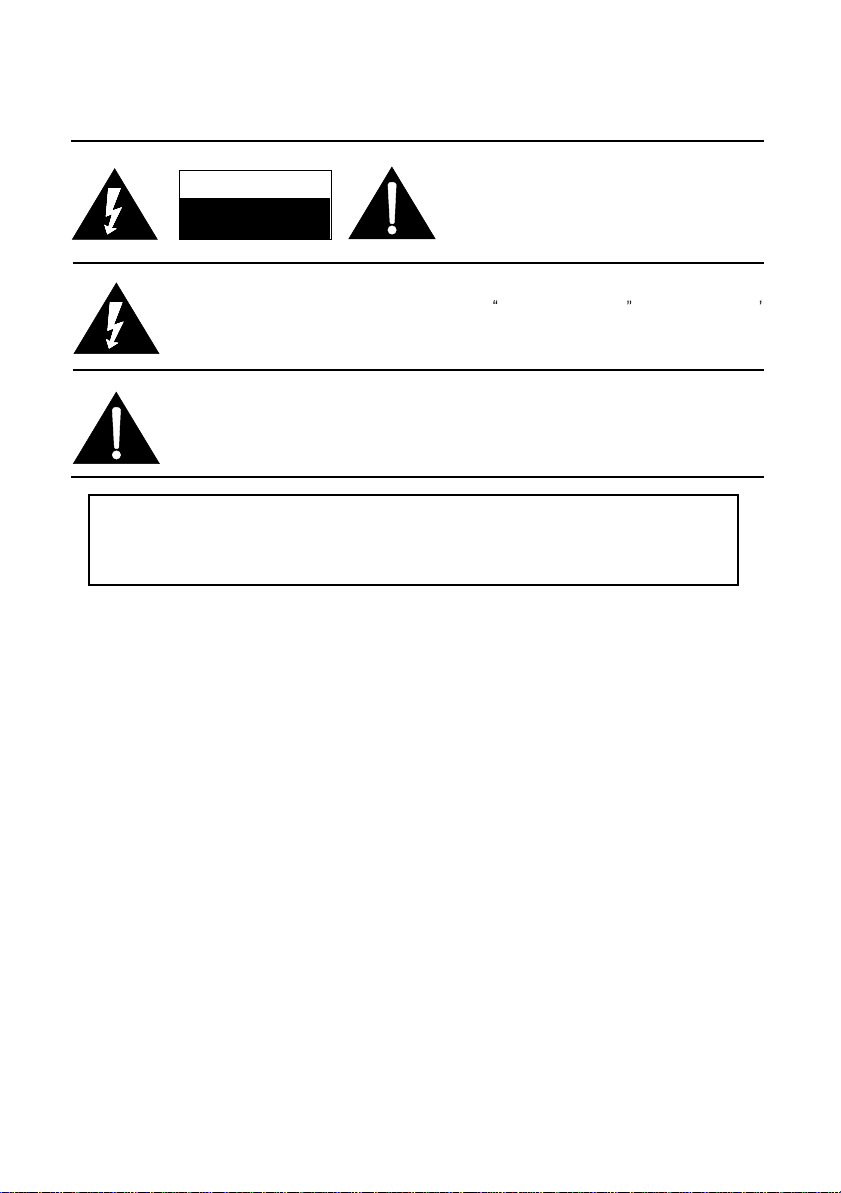
CAUTION: TO REDUCE THE RISK OF
CAUTION
RISK RISK OF OF ELECTRIELECTRICC
SHOCK SHOCK DO DO NOT NOT OPEN.OPEN.
The lighting flash with arrowhead symbol, with an equilateral triangle is intended to
alert the user to the presence of uninsulated voltage within the product s
enclosure that may be of sufficient magnitude to constitute a risk of electric shock to
the person.
The exclamation point within an equilateral triangle is intended to alert the user to the
presence of important operating and maintenance (servicing) instructions in the
literature accompanying the appliance.
ELECTRICAL SHOCK, DO NOT REMOVE
COVER (OR BACK). NO USER SERVICEABLE
PARTS INSIDE. REFER SERVICING TO
QUALIFIED SERVICE PERSONNEL.
dangerous
WARNING: TO REDUCE RISK OF FIRE OR ELECTRIC SHOCK, DO NOT
EXPOSE THIS APPLIANCE TO RAIN OR MOISTURE.
2

IMPORTANT SAFETY INSTRUCTIONS
CAUTION:
Read all of these instructions. Save these instructions for later use. Follo w all Warnings and
Instructions marked on the audio equipment.
1. Read Instructions- All the safety and operating instructions should be read before the product is operated.
2. Retain Instructions- The safety and operating instructions should be retained for future reference.
3. Heed Warnings- All warnings on the product and in the operating instructions should be adhered to.
4. Follow Instructions- All operating and use instructions should be followed.
FOR YOUR PERSONAL SAFETY
1. When the power cord or plug is damaged or frayed, unplug this television set from the wall outlet and refer servicing to
qualified service personnel.
2. Do not overload wall outlets and extension cords as this can result in fire or electric shock.
3. Do not allow anything to rest on or roll over the power cord, and do not place the TV where power cord is subject to
traffic or abuse. This may result in a shock or fire hazard.
4. Do not attempt to service this television set yourself as opening or removing covers may expose you to dangerous
voltage or other hazards. Refer all servicing to qualified service personnel.
5. Never push objects of any kind into this television set through cabinet slots as they may touch dangerous voltage
points or short out par ts that could result in a fire or electric shock. Never spill liquid of any kind on the television set.
6. If the television set has been dropped or the cabinet has been damaged, unplug this television set from the wall outlet
and refer servicing to qualified service personnel.
7. If liquid has been spilled into the television set, unplug this television set from the wall outlet and refer servicing to
qualified service personnel.
8. Do not subject your television set to impact of any kind. Be particularly careful not to damage the picture tube surface.
9. Unplug this television set from the wall outlet before cleaning. Do not use liquid cleaners or aerosol cleaners. Use a
damp cloth for cleaning.
10.1. Do not place this television set on an unstable cart, stand, or table. The television set may fall, causing serious injury
to a child or an adult, and serious damage to the appliance. Use only with a car t or stand recommended by the
manufacturer, or sold with the television set. Wall or shelf mounting should follow the manufacturer s instructions, and
should use a mounting kit approved by the manufacturer.
10.2. An appliance and cart combination should be moved with care. Quick stops, excessive force, and uneven surfaces
may cause the appliance and cart combination to overturn.
3
PROTECTION AND LOCATION OF YOUR SET
11. Do not use this television set near water ... for example, near a bathtub, washbowl, kitchen sink, or laundry tub, in a
wet basement, or near a swimming pool, etc.
Never expose the set to rain or water. If the set has been exposed to rain or water, unplug the set from the wall
outlet and refer servicing to qualified service personnel.
12. Choose a place where light (artificial or sunlight) does not shine directly on the screen.
13. Avoid dusty places, since piling up of dust inside TV chassis may cause failure of the set when high humidity persists.
14. The set has slots, or openings in the cabinet for ventilation purposes, to provide reliable operation of the receiver, to
protect it from overheating. These openings must not be blocked or covered.
Never cover the slots or openings with cloth or other material.
Never block the bottom ventilation slots of the set by placing it on a bed, sofa, rug, etc.
Never place the set near or over a radiator or heat register.
Never place the set in enclosure, unless proper ventilation is provided.
a built-in
PROTECTION AND LOCATION OF YOUR SET
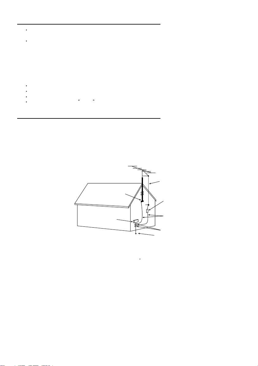
15.1. If an outside antenna is connected to the television set, be sure the antenna system is grounded so as to provide some
protection against voltage surges and built up static charges, Section 810 of the National Electrical Code, NFPA No.
70-1975, provides information with respect to proper grounding of the mast and supporting structure, grounding of the
lead-in wire to an antenna discharge unit, size of grounding conductors, location of antenna discharge unit, connection
to grounding electrode, and requirements for the grounding electrode.
EXAMPLE OF ANTENNA GROUNDING AS PER NATIONAL ELECTRICAL CODE INSTRUCTIONS
EXAMPLE OF ANTENNA GROUNDING AS PER
NATIONALELECTRICAL CODE
ANTENNA
LEAD- INWIRE
GROUND CLAMP
ELECTRIC SERVICE
EQUIPMENT
NEC-NATIONALELECTRICAL CODE
ANTENNA DISCHARGE
UNIT (NEC SECTION
810-20)
GROUNDING
CONDUCTORS
(NECSECTION 810-21)
GROUND CLAMPS
POWER SERVICE GROUNDING
ELECTRODE SYSTEM
(NEC ART 250. PARTH)
15.2. Note to CATV system installer : (Only for the television set with CATV reception)
This reminder is provided to call the CATV system attention to Article 820-40 of the NEC that provides
installer s
guidelines for proper grounding and, in particular, specifies that the cable ground shall be connected to the grounding
system of the building, as close to the point of cable entry as practical.
16. An outside antenna system should not be located in the vicinity of overhead power lines or other electric lights or power
circuits, or where it can fall into such power lines or circuits. When installing an outside antenna system, extreme care
should be taken to keep from touching such power lines or circuits as contact with them might be fatal.
17. For added protection for this television set during a lightning storm, or when it is left unattended and unused for long
periods of time, unplug it from the wall outlet and disconnect the antenna. This will prevent damage due to lightning
and power-line surges.
4

OPERATION OF YOUR SET
18.
This television set should be operated only from the type of power source indicated on the marking label. If you are not
sure of the type of power supply at your home, consult your television dealer or local power company. For television
sets designed to operate from battery power, refer to the operating instructions.
19. If the television set does not operate normally by following the operating instructions, unplug this television set from the
wall outlet and refer servicing to qualified service personnel. Adjust only those controls that are covered in the operating
instructions as improper adjustment of other controls may result in damage and will often require extensive work by a
qualified technician to restore the television set to normal operation.
20. When going on a holiday : If your television set is to remain unused for a period of time, for instance, when you go on
a holiday, turn the television set and unplug the television set from the wall outlet.
off
IF THE SET DOES NOT OPERATE PROPERLY
21. If you are unable to restore normal operation by following the detailed procedure in your operating instructions,
do not attempt any further adjustment. Unplug the set and call your dealer or service technician.
22. Whenever the television set is damaged or fails, or a distinct change in performance indicates a need for
service, unplug the set and have it checked by a professional service technician.
23. It is normal for some TV sets to make occasional snapping or popping sounds, particularly when being
turned on or off. If the snapping or popping is continuous or frequent, unplug the set and consult your
dealer or service technician.
FOR SERVICE AND MODIFICATION
24. Do not use attachments not recommended by the television set manufacturer as they may cause hazards.
25. When replacement parts are required, be sure the service technician has used replacement parts specified
by the manufacturer that have the same characteristics as the original part. Unauthorized substitutions
may result in fire, electric shock, or other hazards.
26. Upon completion of any service or repairs to the television set, ask the service technician to perform
routine safety checks to determine that the television is in safe operating condition.
5

PRODUCT SPECIFICATION
MODEL:::: GV-1475
AMBIENT CONDITIONS::::
AMBIENT TEMPERATURE::::
OPERATING::::-10°°°°C ~ +40°°°°C
STORAGE::::-15°°°°C ~ +45°°°°C
HUMIDITY
OPERATING:<
STORAGE: <<<<90%
AIR PRESSURE: 86kpa ~ 106kpa
PREPARED BY : DATE:
:<80%
:<:<
APPROVED BY: DATE:
6
A: GENERAL SPECIFICATION:
1: CRT
X 37cm(14”) 51cm (20”)
54cm(21”) 64cm (25”)
74cm (29”) 84cm (34”) OTHER
2: CHASSIS:
DIGITAL NICAM STEREO X ANALOG
SURROUND SOUND TELETEXT GERMAN STEREO
S.VHS OTHER
3: CPU:
TSB M5C01 TSB M5C03 TSB M5ENG TSB M6/M6A TSB M7/M7A
TSB M8A TSB M8B TSB CTS-654A TSB M2A SS M4F
PHIL.CTV 222S MIT.(2911) SIE SDA 5352 X OTHERS M17
4: TV BROADCASTING SYSTEM AND COUNTRY
PAL-I PAL-BG PAL-DK PAL-DK.1
X PAL-DK.BG SECAM-BG SECAM-L X SECAM-DK.BG
PAL-N NTSC-M X NTSC3.579/4.43 AV MODE 21 MULTI
SYSTEM
UK HK GERMAN RUSSIA
CHINA USA E.EUROPE VIETNAM
CANADA DUBAI INDONESIA S.AFRICA)
MALAYSIA MID. AMERICA SINGAPORE
ISRAEL AUSTRALIA & NEW ZEALAND
TAIWAN X MOROCCO PHILIPPINES OTHER
5: RECEIVING CHANNELS
CH21--CH69 CH2--CH12(CCIR)
CHFA-CHS20(FRANCE BAND) CH2--CHS41(HYPER BAND)
CH21--CH69(FRANCE BAND) CH21--CH69(HYPER BAND)
7

CH2--CHS20(CABLE BAND) CH2--CH13(USA BAND)
CH21--CH69(CABLE BAND) CH14--CH83(USA BAND)
CHR1--CHR12(OIRT) CH1--CH12/CH13-CH57(CHINA BAND)
X OTHER CATV 470MHz
6: SCANNING LINES AND FREQUENCIES
625 LINES 15.625kHz 50Hz
525 LINES 15.75kHz 60Hz
X 525/625 LINES 15.625kHz /15.75kHz 50/60Hz
7: COLOUR SUB-CARRIER
X 4.433MHz
X 3.579MHz
3.58MHz
8: INTERMEDIATE FREQUENCIES
PICTURE 39.5MHz SOUND 6.0MHz
X PICTURE 38.9MHz X SOUND5.5MHz
PICTURE 38.0MHz X SOUND 6.5MHz
PICTURE 45.75MHz SOUND 4.5MHz
OTHER AM SOUND 6.5MHz
9: POWER CONSUMPTION:
65W X 70W 75W 80W 110W 120W
130W 140W 180W 190W OTHER
10: POWER SOURCE:
AC 120V 60Hz±10%
AC 200V 50Hz±10%
AC 220V 50Hz±10%
AC 220V 50Hz+10%~25%
AC 240V 50Hz±10%
X AC 110V-240V 50/60Hz±10%
OTHER
8

11: AUDIO OUTPUT POWER (7%THD)
13”& 14”---1W
20”& 21”---2W
20”& 21”---2W + 2W (R + L)
25”---4W + 4W (R + L)
29”---6W + 6W (R + L)
34”---8W + 8W(R + L)
X OTHER 14”>=2W+2W
12: AERIAL INPUT IMPEDANCE
X 75 Ω UNBALANCED DIN JACK ANT.INPUT75
75Ω UNBALANCED F TYPE ANT.INPUT FOR NTSC
300 Ω BALANCED(TWO TERMINALS ANT.INPUT)
OTHER
13: PRODUCT SAFETY REQUIREMENT
BS APPROVAL
VDE APPROVAL
UL APPROVAL
X CHINA APPROVAL
CB APPORVAL
OTHER
14: PRODUCT EMC/EMI REQUIREMENT
FTZ APPOVAL
FCC APPROVAL
X CHINA APPOVAL
OTHER
B: BASIC FEATURES OF CONTROLLER
1: CHANNEL TUNING METHOD
9
X VOLTAGE SYNTHESIZER (V.S.)
PLL FREQUENCY SYNTHESIZER (F.S.)
2: PRESETTABLE PROGRAM
50 PROGRAMS 99 PROGRAMS
X 100 PROGRAMS 181 PROGRAMS
OTHER
3: TUNING FOR VHF AND UHF BANDS
X AUTO SEARCH X MANUAL TUNING
X FINE TUNING
4: PICTURE AND SOUND ADJUSTMENT
X BRIGHT,CONTRAST,COLOUR AND VOLUME CONTROL
X TINT CONTROL(NTSC)
TREBLE,BASS,BALANCE CONTROL
X SHARPNESS CONTROL OTHER
5: TELETEXT
SIMPLE TEXT TOP(TABLE OF PAGES)
FLOF (FASTEXT) LIST
6: ON SCREEN DISPLAY
X GENERAL FEATURES∗ STEREO DUAL LAN.
FOUR S.EFFECT INDICATOR GERMAN STEREO INDICATOR
∗REMARK:OSD-GENERAL FEATURES OF CPU:
VOLUME,BRIGHTNESS,CONTRAST,COLOUR,PROGRAM,BAND,
AUTO SEARCH,MANUAL,TUNE,MUTING,AV AND SLEEP TIMER.
7: SLEEP TIMER
X 10-120 MINUTES WITH 10M.INCREMENT
8: AUTO OFF WHEN NO BROADCASTING SIGNAL
10 min X 15 min 20 min
10
9: FULL FUNCTION INFRARED REMOTE CONTROL
P/N OF REMOTE CONTROL INLAY : 58-HS46F0-YUI
10: REMOTE EFFECTIVE DISTANCE 8 m
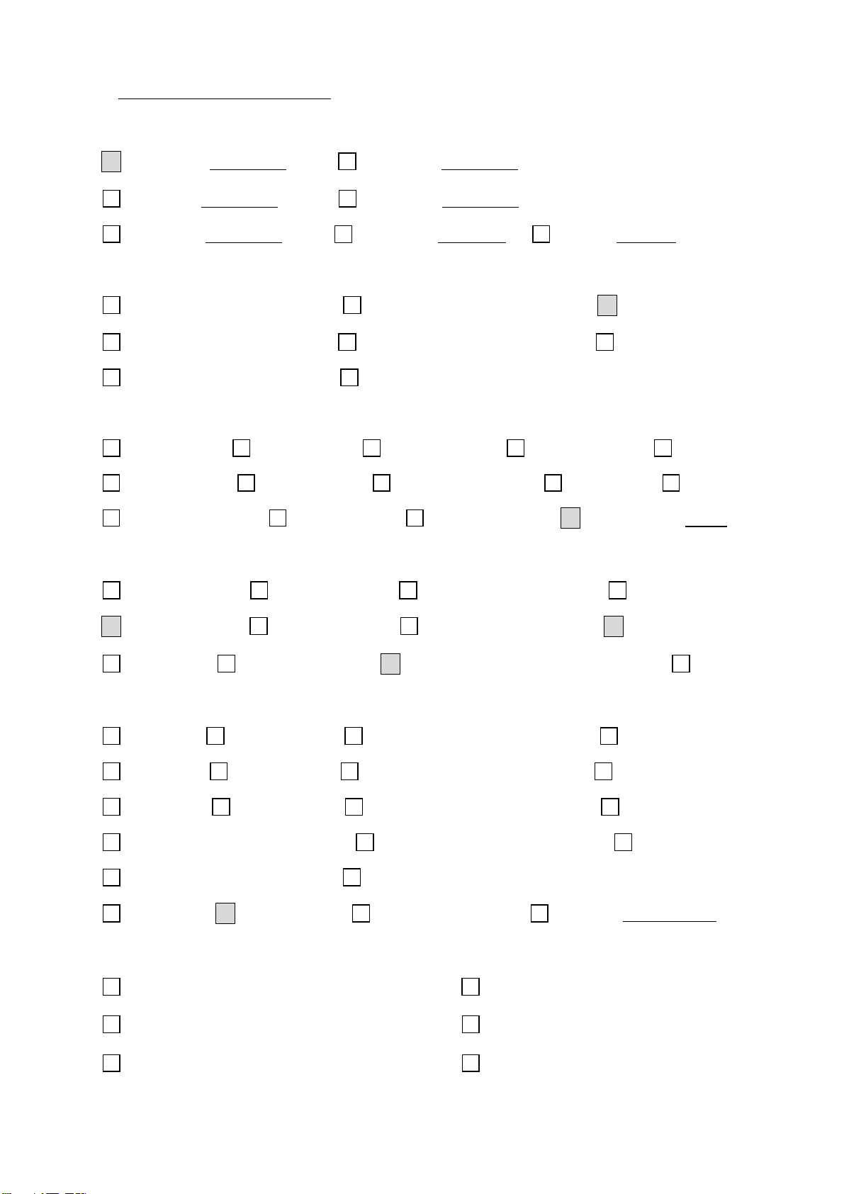
C: CONSTRUCTION OF FRONT PANEL
X MAIN POWER SWITCH FUNCTION SELECT
X REMOTE SENSOR X MENU SELECT
SYSTEM FUNCTION S.VHS INPUT
MICROPHONE INPUT X TV/AV SELECT
X STANDBY INDICATOR X PROGRAM VOLUME UP/DOMN
BAND SELECT X RCA SOCKET<SIDE>
EARPHONE INPUT OTHER
AUTO SEARCH AND MANUAL TUNING SELECT
D: CONSTRUCTION OF REAR PANEL
X 75Ω AERIAL TERMINAL
300Ω AERIAL TERMINAL
RCA SOCKET(AV INPUT ONLY)
RCA SOCKET--AV IN/OUT
RCA SOCKET --A-R+L IN/OUT,V- IN/OUT
RCA SOCKET --A-R+L /V INPUT X 2
X SCART SOCKET
S.VHS INPUT
EXT/INT SPEAKER SELECT
EXT.SPEAKERS(R+L)TERMINALS
EXT.SPEAKERS(R+L)RCA SOCKET
SUPER WOOFER TERMINAL
OTHER
E: AUDIO AND VIDEO INPUT/OUTPUT
11
RCA SOCKET
X SCART SOCKET(AV)
SCART SOCKET (FULL)
SPECIFICATION SCART RCA
VIDEO INPUT 75Ω
1V
1V
P-P
P-P
AUDIO INPUT 10kΩ (R+L)
VIDEO OUTPUT 75Ω
AUDIO OUTPUT 1kΩ (R+L)
RGB INTPUT 75Ω
AUDIO LINE OUTPUT 1kΩ
0.5V
1V
0.5V
0.7V
1V
0.5V
rmS
1V
P-P
0.5V
rmS
P-P
P-P
P-P
rmS
rmS
F: OTHERS INFORMATION
1.FLYBACK: 37-BSC250-231
2.TUNER: 07-389VI5-NX4
3.SAW FILTER: 45-SAW296-6M00G
4.POWER CORD:
5.FUSE:
6.COLOUR TEMP:
7.MAGNETIC FIELD:
8.IC EEPROM: 13-00M24C-04P
9.IR RECEIVER: 11-IRR001-1X0
10.CIRCUIT DIAGRAM: 01-1418MU-M35
11. MAIN BOARD: 40-2111MU-MAK01
12

Parent Item No. Item No. Description Quantity Req. Designato
r
Remarks
03-1475MU-MR35 08-01436U-CRY ASS'Y - CRT BD 1
08-01436U-CRY 10-1N4148-ABX DIODE 1N4148 (SWITCHING) 1 D501
08-01436U-CRY 10-1N4148-ABX DIODE 1N4148 (SWITCHING) 1 D502
08-01436U-CRY 11-SC2482-0BX TRANSISTOR 2SC2482 1 Q501
08-01436U-CRY 11-SC2482-0BX TRANSISTOR 2SC2482 1 Q503
08-01436U-CRY 11-SC2482-0BX TRANSISTOR 2SC2482 1 Q505
08-01436U-CRY 11-A562TM-0BX TRANSISTOR 2SA562TM-0 1 Q507
08-01436U-CRY 11-SC1815-YBX TRANSISTOR 2SC1815Y 1 Q502
08-01436U-CRY 11-SC1815-YBX TRANSISTOR 2SC1815Y 1 Q504
08-01436U-CRY 11-SC1815-YBX TRANSISTOR 2SC1815Y 1 Q506
08-01436U-CRY 18-CB0102-JNX RES. C.F. 1K OHM 1/6W +/-5% 1 R515
08-01436U-CRY 18-CB0272-JNX RES. C.F. 2.7K OHM 1/6W +/-5% 1 R514
08-01436U-CRY 18-CB0561-JNX RES. C.F. 560 OHM 1/6W +/-5% 1 R503
08-01436U-CRY 18-CB0561-JNX RES. C.F. 560 OHM 1/6W +/-5% 1 R508
08-01436U-CRY 18-CB0561-JNX RES. C.F. 560 OHM 1/6W +/-5% 1 R513
08-01436U-CRY 18-CB0561-JNX RES. C.F. 560 OHM 1/6W +/-5% 1 R501
08-01436U-CRY 18-CB0561-JNX RES. C.F. 560 OHM 1/6W +/-5% 1 R505
08-01436U-CRY 18-CB0561-JNX RES. C.F. 560 OHM 1/6W +/-5% 1 R510
08-01436U-CRY 18-CB0681-JNX RES. C.F. 680 OHM 1/6W +/-5% 1 R502
08-01436U-CRY 18-CB0681-JNX RES. C.F. 680 OHM 1/6W +/-5% 1 R506
08-01436U-CRY 18-CB0681-JNX RES. C.F. 680 OHM 1/6W +/-5% 1 R509
08-01436U-CRY 18-CB0681-JNX RES. C.F. 680 OHM 1/6W +/-5% 1 R511
08-01436U-CRY 18-CB0681-JNX RES. C.F. 680 OHM 1/6W +/-5% 1 R522
08-01436U-CRY 18-FE0272-JNX RES. M.O. 2.7K OHM 1/2W +/-5% 1 R519
08-01436U-CRY 18-FE0272-JNX RES. M.O. 2.7K OHM 1/2W +/-5% 1 R520
08-01436U-CRY 18-FE0272-JNX RES. M.O. 2.7K OHM 1/2W +/-5% 1 R521
08-01436U-CRY 18-FG0123-JHX RES. M.O. 12K OHM 2W +/-5% 1 R516
08-01436U-CRY 18-FG0123-JHX RES. M.O. 12K OHM 2W +/-5% 1 R517
08-01436U-CRY 18-FG0123-JHX RES. M.O. 12K OHM 2W +/-5% 1 R518
08-01436U-CRY 25-BLA100-M1X CAP. ELEC 10 UF 250V +/-20% 1 C504
08-01436U-CRY 26-AMK182-KBX CAP. CER 1800PF 2KV +/-10% 1 C505
08-01436U-CRY 26-EBP102-KBX CAP. CER 1000 PF 50V +/-10% B 1 C509
08-01436U-CRY 26-EBP102-KBX CAP. CER 1000 PF 50V +/-10% B 1 C508
08-01436U-CRY 26-EBP471-JCX CAP. CER 470PF 50V +/-5% CH 1 C501
08-01436U-CRY 26-EBP471-JCX CAP. CER 470PF 50V +/-5% CH 1 C502
08-01436U-CRY 26-EBP471-JCX CAP. CER 470PF 50V +/-5% CH 1 C503
08-01436U-CRY 34-R100K2-1BX COIL CHOKE 10 UH +/-10% 1 L502
08-01436U-CRY 35-139730-00X FERR. BEAD BF60 2 FOR C508 (L505 & L506)
08-01436U-CRY 40-291210-0AE P.C.B. CRT BD 1
08-01436U-CRY 41-WJ0050-B00 WIRE BARE JUMPER 5MM 1 L501
08-01436U-CRY 41-WJ0050-B00 WIRE BARE JUMPER 5MM 1 L503
13

08-01436U-CRY 41-WJ0050-B00 WIRE BARE JUMPER 5MM 1 L504
08-01436U-CRY 41-WJ0060-B00 WIRE BARE JUMPER 6mm 1 R507
08-01436U-CRY 41-WJ0060-B00 WIRE BARE JUMPER 6mm 1 R504
08-01436U-CRY 41-WJ0060-B00 WIRE BARE JUMPER 6mm 1 R512
08-01436U-CRY 41-WJ0060-B00 WIRE BARE JUMPER 6mm 1 J501
08-01436U-CRY 46-10967W-01X PIN BASE *1 TJC1-1A 1 FOR CRT GROUNDING
08-01436U-CRY 46-33624H-04X HS 3P 2468#24 270 TJC3-4Y/SCN-4Y 1 P502 FOR M.BD P402
08-01436U-CRY 46-33630H-05X HS 5P24 280 F/W TJC3-5Y/SCN-5Y 1 P503 FOR M.BD P201
08-01436U-CRY 47-CRT009-CX0 SOCKET CRT 12P GZS12-4-2 1 S501
08-01436U-CRY 25-BCB471-M1X CAP. ELEC 470 UF 16V +/-20% 1 C506
03-1475MU-MR35 08-01436U-PWY ASS'Y - POWER PARTS (AC110~) 1
08-01436U-PWY 18-KE0475-JNX RES. H. VOLT. CC 4.7M OHM 1/2W 1 R835A
08-01436U-PWY 10-00RU3C-F0X DIODE RU3C (FAST RECTIFIER) 1 D824
08-01436U-PWY 10-0RL255-EBX DIDEO RL255 (RECTIFIER) 1 D801
08-01436U-PWY 10-0RL255-EBX DIDEO RL255 (RECTIFIER) 1 D802
08-01436U-PWY 10-0RL255-EBX DIDEO RL255 (RECTIFIER) 1 D803
08-01436U-PWY 10-0RL255-EBX DIDEO RL255 (RECTIFIER) 1 D804
08-01436U-PWY 10-1N4148-ABX DIODE 1N4148 (SWITCHING) 1 D805
08-01436U-PWY 10-1N4148-ABX DIODE 1N4148 (SWITCHING) 1 D807
08-01436U-PWY 10-1N4148-ABX DIODE 1N4148 (SWITCHING) 1 D832
08-01436U-PWY 10-1N4148-ABX DIODE 1N4148 (SWITCHING) 1 R823
08-01436U-PWY 10-79C8V2-DBX DIODE ZENER 8V2 1/2W 5% 1 D833
08-01436U-PWY 11-SC1815-YBX TRANSISTOR 2SC1815Y 1 Q806
08-01436U-PWY 13-TDA168-46P IC TDA16846 (SMPS) 1 IC801
08-01436U-PWY 18-CB0102-JNX RES. C.F. 1K OHM 1/6W +/-5% 1 R829
08-01436U-PWY 18-CB0182-JNX RES. C.F. 1.8K OHM 1/6W +/-5% 1 R804
08-01436U-PWY 18-CB0222-JNX RES. C.F. 2.2K OHM 1/6W +/-5% 1 R827
08-01436U-PWY 18-CB0470-JNX RES. C.F. 47 OHM 1/6W +/-5% 1 R826A
08-01436U-PWY 18-CB0472-JNX RES. C.F. 4.7K OHM 1/6W +/-5% 1 R826
08-01436U-PWY 18-CB0472-JNX RES. C.F. 4.7K OHM 1/6W +/-5% 1 R828
08-01436U-PWY 18-CB0563-JNX RES. C.F. 56K OHM 1/6W +/-5% 1 R812
08-01436U-PWY 18-CB0563-JNX RES. C.F. 56K OHM 1/6W +/-5% 1 R806
08-01436U-PWY 18-CB0752-JNX RES. C.F. 7.5K OHM 1/6W +/-5% 1 R810
08-01436U-PWY 18-CB0823-JNX RES. C.F. 82K OHM 1/6W +/-5% 1 R803
08-01436U-PWY 18-CD0101-JNX RES. C.F. 100 OHM 1/4W +/-5% 1 R808
08-01436U-PWY 18-CD0153-JNX RES. C.F. 15K OHM 1/4W +/-5% 1 R811
08-01436U-PWY 18-CD0470-JNX RES. C.F. 47 OHM 1/4W +/-5% 1 R808A
08-01436U-PWY 18-CE0102-JNX RES. C.F. 1K OHM 1/2W +/-5% 1 R808B
08-01436U-PWY 18-EF0228-JGX RES. FUS. 0.22 0HM 1W +/-5% 1 R834
08-01436U-PWY 18-EF0228-JGX RES. FUS. 0.22 0HM 1W +/-5% 1 R836
08-01436U-PWY 18-FE0120-JNX RES. M.0. 12 OHM 1/2W +/-5% 1 R825
08-01436U-PWY 18-FG0121-JHX RES. M.O. 120 OHM 2W +/-5% 1 R819A
14
 Loading...