

Page 1

.
GAS CONVECTION OVEN
GAS CONVECTION OVEN
GAS CONVECTION OVEN GAS CONVECTION OVEN
PROUDLY AUSTRALIAN MADE
INSTALLATION PROCEDURE – USER MANUAL
SERVICE INSTRUCTION
MODEL X500A
MODEL X500A
MODEL X500A MODEL X500A
ELECTRICAL APPROVAL CS 4049
GAS APPROVAL SC 378
ESTABLISHED 1911
The Cooking Equipment Professionals
www.goldsteineswood.com.au
Page 2

TABLE OF CONTENTS
1. INTRODUCTION Page 3
2. INSTALLATION Page 4 – 5 & 6
3. COMMISSIONING Page 7
4. OPERATING INSTRUCTIONS Page 8
5, CONTROLS Page 9
6. TECHNICAL INSTRUCTIONS Page 10
7. TECHNICAL DATA Page 11 – 12 - 13
8. ELECTRICAL CONNECTION Page 14
9. GUIDE FOR COOKING TIMES TEMP. Page 15
10. CLEANING INSTRUCTIONS Page 16 & 17
11. PROBLEM SOLVING Page 18 – 19 - 20
12. WIRING DIAGRAM Page 21 & 22
13. CONNECTION DIAGRAM Page 23
14. BLOWER WHEEL FAN Page 24
15. DRAWINGS Page 25
16. SPARE PARTS Page 26
17. WARRANTY Page 27
18. BRANCHES Page 28
2
IM067B2 – June 2010
Page 3

1. INTRODUCTION
Congratulations for purchasing your Goldstein commercial cooking appliance.
J. Goldstein & Co. is a wholly owned Australian company and has been
operating since 1911, building high quality products. The information in this
manual will assist your installer and ensure correct location and connection.
Thoroughly read the user instructions and the user maintenance sections, as
understanding your products, its operation, and its cleaning and service
requirements will provide you with long and satisfactory service. Failure to do so
could shorten the life of the product and decrease its efficiency. Please ensure
only authorised service technicians are called to any difficulties that may arise.
INTRODUCTION
GOLDSTEIN GAS CONVECTION OVEN
MODEL X500A
GOLDSTEIN GAS CONVECTION OVENS are designed to give long and satisfactory
service and incorporate the best possible materials and workmanship. Proper
installation, adjustment and preventative maintenance are vitally important if efficiency
and appearance are to be maintained.
Read these instructions carefully as they contain important safety information regarding
the installation, use and maintenance of the appliance.
RECEIVING INSPECTION
•
Check crates for handling damage. After carefully uncrating, check for “concealed”
damage. Report any damage immediately to carrier and to dealer.
•
Remove check all loose items from unit and check contents as found on back of
warranty card.
•
Check type and capacity of gas supply & Electrical rating on the rating plate.
•
The type of gas for which this Oven is factory adjusted can be seen on the rating
plate, located on the front bottom panel (below the doors).
“THE EQUIPMENT MUST BE INSTALLED BY A LICENSED GASFITTER AND
LICENSED CONTRACTOR”
3
IM067B2 – June 2010
Page 4

2. INSTALLATION INSTRUCTIONS
PRE-INSTALLATION OF THE X500
Assemble legs to X500A
To assemble the legs place two pieces of timber approx. the depth of the unit covered
with plastic on the floor beside the unit. Tip the unit over onto these two pieces of
timber exercising care not to jam your hands.
Then proceed to bolt the legs onto each corner after the legs are in place bolt the metal
shelf into place which helps align the legs. When this is complete then carefully raise
the unit up onto its legs.
Levelling of X500A
X500A have a levelling adjustment at the bottom of each leg. Start with this adjustment
screwed all the way in. With a spirit level placed on an oven rack check and level side
to side first, then front to back, this is important as floors can be out 75mm of level.
ELECTRICAL CONNECTION
The electric motor, indicator light and related switch, are all connected to a terminal
block found at the top of the oven. The supply cord must be plugged into a properly
ground three-prong receptacle. Do not cut or remove the grounding prong from the
plug.
Normal factory connections are made for operation on 240 volt AC50 cycle.
VENTILATION
Proper ventilation is essential for good oven operation. When a hood is used as means
of ventilation, it should extend at least 150mm beyond all sides of oven (except against
a wall, if it is a wall installation). Oven must be 50mm off wall.
IMPORTANT
If the oven is to be “built-in”, adequate air space for proper venting of the motor must be
provided at the bottom and top of the unit, or WARRANTY WILL BE VOID.
IM067B2 – June 2010
4
Page 5

2. INSTALLATION INSTRUCTIONS
Follow these instructions carefully.
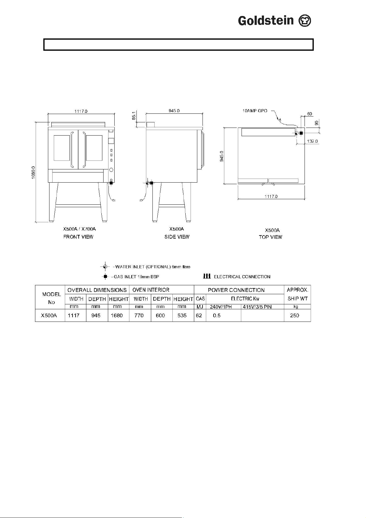
1. Have a licensed gas fitter or our local gas company connect the appliance to the
mains pressure supply. The gas inlet connection can be seen in the appendix on
Page 11. The appliance must be installed in accordance with rules of any
authority having jurisdiction as per below. The regulator is built into the gas
control, behind side panel on Page 11.
NOTE: The appliance must be installed by an authorised Gas Fitter and in
accordance with the regulations of the local Gas Authority, AS5601/AG601
and any other authority having jurisdiction. The appliance has been tested
and preset before leaving our factory, but small adjustments may be
necessary to suit local conditions. Correct operation of the appliance must
be tested as part of the installation procedure. Check Page 7
Commissioning.
Licensed Gas Fitter should make connection to main gas line. Install a hand
shut-off valve in gas line to the appliance manifold.
As from 1st January 2005. The new AGA AS4563/AG300 codes states that all L.P.G.
appliance will be supplied with a separate regulator for each appliance.
FAILURE TO DO SO WILL VOID
WARRANTY ON THE EQUIPMENT
PLEASE RETURN YOUR WARRANTY CARD
NOTICE
IM067B2 – June 2010
5
Page 6

2. INSTALLATION INSTRUCTIONS
INSTALLATION
(FOR AUTHORISED INSTALLER ONLY)
Note: AFTER ANY MAINTENANCE OR ADJUSTING OF GAS CONNECTED
COMPONENTS, A GAS LEAK TEST MUST BE CARRIED OUT, TO ENSURE THERE
ARE NO GAS LEAKING HAZARDS
GAS CONNECTION
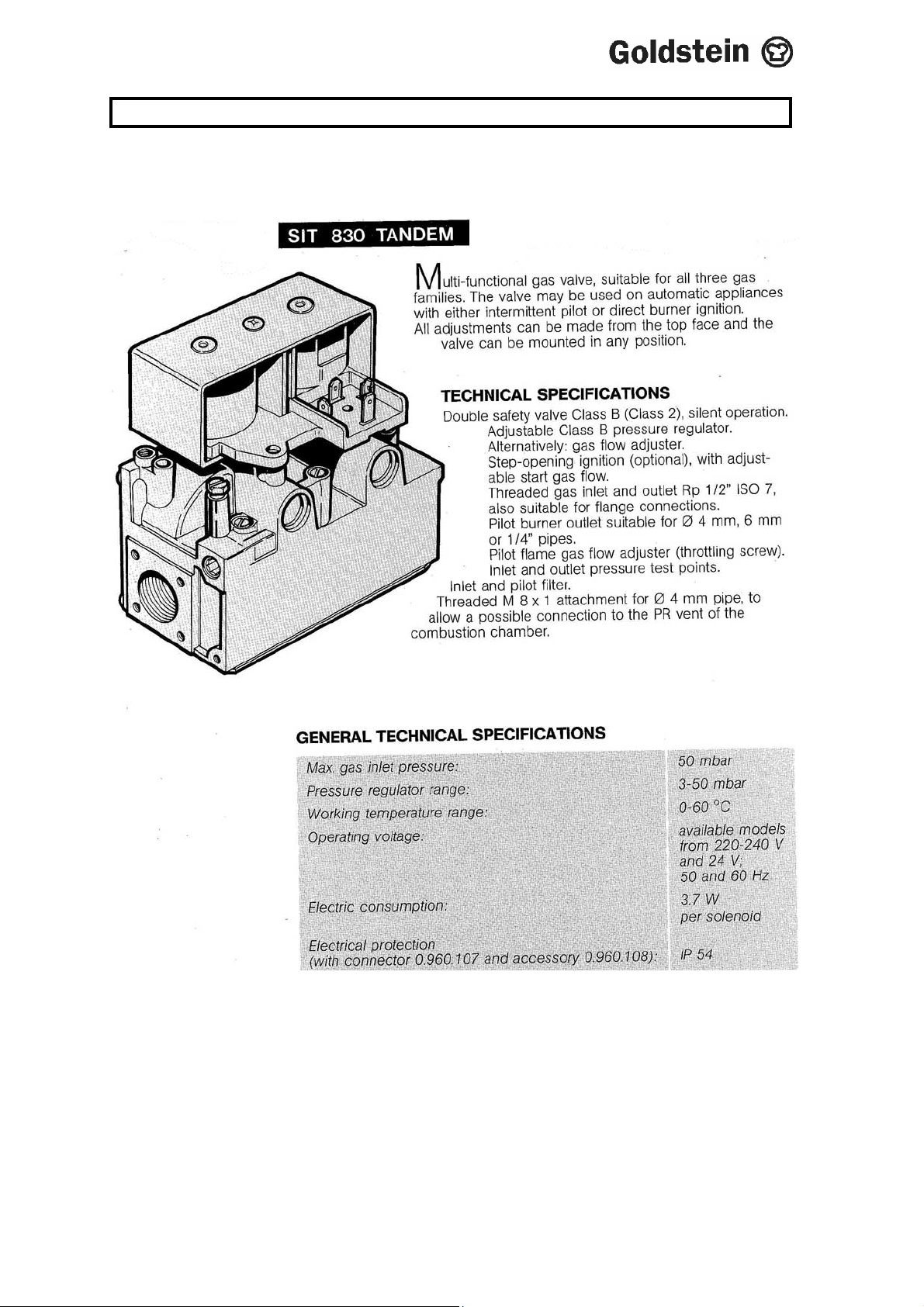
The gas pressure regulator is part of the 830 TANDEM - SIT Control and not a separate
item. Note: Any inlet pressure above 2.7 kPa must have an inline gas regulator before
the unit. It is important that adequately sized piping be run directly to point of
connection on oven with as few tees and elbows as possible. Always install an
accessible shut-off valve adjacent to oven.
When making gas pipe connections the pipe joint compound should be resistant to the
action of liquefied petroleum gases.
A. If gas specified on rating plate (located on bottom front panel) does not
correspond with gas supplied, notify your dealer immediately.
B. Check gas pressure at Test nipple on the outlet side of the 830 SIT Control. The
control pressure e.g. as on Page 12 should be 0.92 Kpa on Natural gas and
2.60 Kpa on LP gases. When checking gas Test Point Pressure, be sure other
equipment on the same gas line is “ON”. This will allow you to set the T.P.P.
while the oven is under a high load.
T.P.P. can be adjusted using a screw driver to turn the adjusting screw of the SIT
control 830 in centre of body.
ON SITE OVEN TEST
When the oven has been installed, proceed as follows to check that oven works
according to the manufacturers requirements.
Ensure that the fan turns in the direction indicated on the Fan Motor.. Ensure
that the fan (located in the rear of the oven) cuts off when oven doors are
opened.
Ensure that once oven reaches pre-set temperature that burner flame cuts off,
then cuts back in when oven temperature drops 2-3 degrees below pre-set
temperature.
CAUTION: BEFORE PERFORMING ANY MAINTENANCE ON THIS UNIT,
DISCONNECT FROM MAIN POWER SUPPLY.
IM067B2 – June 2010
6
Page 7

3. COMMISSIONING INSTRUCTIONS
COMMISSIONING CHECK LIST
1. CHECK FOR DAMAGE AND MISSING PARTS.
2. REMOVE ALL PLASTIC COATING FROM S/STEEL PANELS.
3. MAKE SURE ALL PARTS ARE IN THEIR CORRECT POSITION E.G. TRAYS
BURNERS KNOBS.
4. MAKE SURE ALL GAS CONNECTIONS ARE CORRECT AND TIGHT.
5. LEVEL OFF UNIT LEFT TO RIGHT AND ALSO MAKE SURE THAT FRONT IS
JUST 3-4 MM LOWER TO ALLOW FOR FLUING.
6. TURN ON GAS .
7. ADJUST GAS PRESSURE WITH THREE-QUARTERS OF THE UNIT
RUNNING, ADJUST GAS PRESSURE.
NATURAL GAS 1.00 KPA ) as per pressure shown
LPG 2.60 KPA ) on Rating Plate
8. TURN ON ONE AT A TIME TO MAKE SURE ALL IS WORKING E.G. BURNER,
RADIANT, GRIDDLE AND STEAMER.
9. SHOW CUSTOMER
A) HOW TO WORK EQUIPMENT
B) HOW TO CLEAN
C) HOW TO PULL IT APART E.G. TRAYS, TRIVETS.
D) ALSO WHAT NOT TO DO, E.G. GREASE AND OIL IN CONTROLS.
10. CHECK TO MAKE SURE MANUALS AND WARRANTY CARDS ARE THERE.
ALSO GO THROUGH MANUAL WITH CUSTOMER E.G. LIGHTING,
CLEANING.
NOTE
HOSES SHOULD NEVER BE USED ON THE APPLIANCE.
USE OF HOSES WILL VOID WARRANTY
“DO NOT SPRAY AEROSOLS IN VICINITY OF APPLIANCE WHILST
OPERATING”
7
IM067B2 – June 2010
Page 8

4. OPERATING INSTRUCTIONS
OVEN OPERATING INSTRUCTIONS
Due to increased efficiency of this oven the temperature of the standard recipes should
be reduced approximately 20°C.
Always load each shelf evenly. Space pans away from each other and from sides and
back of oven to allow a maximum of airflow between them.
The moving air continually strips away thin layers of moisture and cool air from the top
of the goods allowing the heat to penetrate more quickly, thus shortening the cooking
time and permitting use of lower temperatures.
Cook the product in less time than it would take to bake in a Static or Normal oven.
Depending on the item and the type of pan used, time saving may run from 20% to a
high of 50%. A damper lever on the control panel keeps steam in when you want moist
heat – but permits you to let it out fro dry heat.
With stainless steel interiors, this oven is designed to be as maintenance free as
possible. However, for best operating results, the oven should be cleaned regularly and
the controls should be adjusted periodically.
8
IM067B2 – June 2010
Page 9
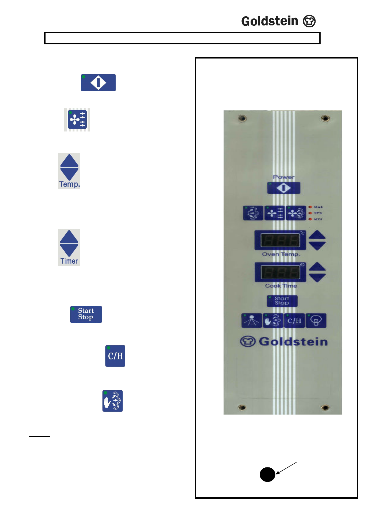
operate until the set time has elapsed and the buzzer sounds.
Reset
5. CONTROLS
COOKING CYCLE
(i) Turn on Power .
(ii) Select the cooking mode by pressing the
Convection Button
(iii)
Press button up or down to set desired
temperature, the display will flash to indicate the
setting mode, when arrow is released set temperature
will display for 3 seconds and then display will stop
flashing and read actual oven temperature.
(iv)
Press button up or down to set desired
cooking time. Timer display will flash to indicate that
it is in the setting mode, it will stop after the button
has been released and will display the set cooking
time.
X500
(viii) Press the button so that the green LED
lights up. This will start the cooking cycle which will
(ix) Cook & Hold. Press the button. It will hold the
oven temperature at 70ºC after the cooking cycle finishes,
for up to 999 minutes.
(x) Hand Steam. Press the button; it will inject
steam, for 2 seconds.
NOTE
Push the Pilot reset button, if the light is on.
If the light remains ON after 3 or 4 attempts, call
a Service Technician
Pilot
Button
IM067B2 – June 2010
9
Page 10

6. TECHNICAL INSTRUCTIONS
GAS CONNECTION
Have a licensed gas fitter or your local Gas Authority connect the appliance.
It is recommended that a valve and union be installed close to the appliance for
disconnection in the event of service.
Check thoroughly for gas leaks before attempting to light the appliance.
Check that all burners are in position.
Peel off all protective plastic and remove any glue with a solvent.
IMPORTANT
READ THIS INSTRUCTION MANUAL CAREFULLY BEFORE LIGHTING AND USE.
GAS INLET CONNECTION
19mm NB BSP from below the appliance, 60mm from the right hand side looking at the
front of the appliance as shown on Page 11.
Electrical connection is a two (2) metre Three (3) pin flexible lead as shown on Page 11.
As from 1st January 2005. The new AGA AS4563/AG300 codes states that all L.P.G.
appliance will be supplied with a separate regulator for each appliance.
IM067B2 – June 2010
10
Page 11
7. TECHNICAL DATA
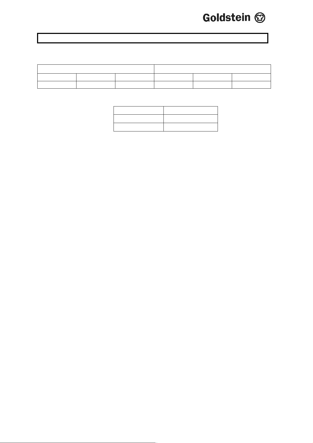
GAS CONSUMPTION AND INJECTOR SIZES
NG LPG
Mm Drill Mj Mm Drill Mj
2.60 38 60 1.70 51 65
TTP TTP
KPA KPA
0.92 2.60
GAS CONTROL - SPECIFICATION
S.I.T. 830 Tandem
- Thermoelectric flame failure device
- Low rate ignition regulator
- Servo system pressure regulator
- Ignition restart interlock
- Inlet-outlet pressure test point
Illustrated on Page 12 & 13
CONVERSION TO L.P. GAS
1. Disconnect oven from gas/electrical supply.
2. Install LPG governor as per AGA Code AS4563/AG300.
3. Change burner injector as per table.
4. Connect gas and electrical supply.
5. Start oven to see burner flame.
6. Set T.P.P. as per table.
7. Step through installation/commissioning instructions.
11
IM067B2 – June 2010
Page 12
7. TECHNICAL DATA
12
IM067B2 – June 2010
Page 13
7. TECHNICAL DATA
13
IM067B2 – June 2010
Page 14
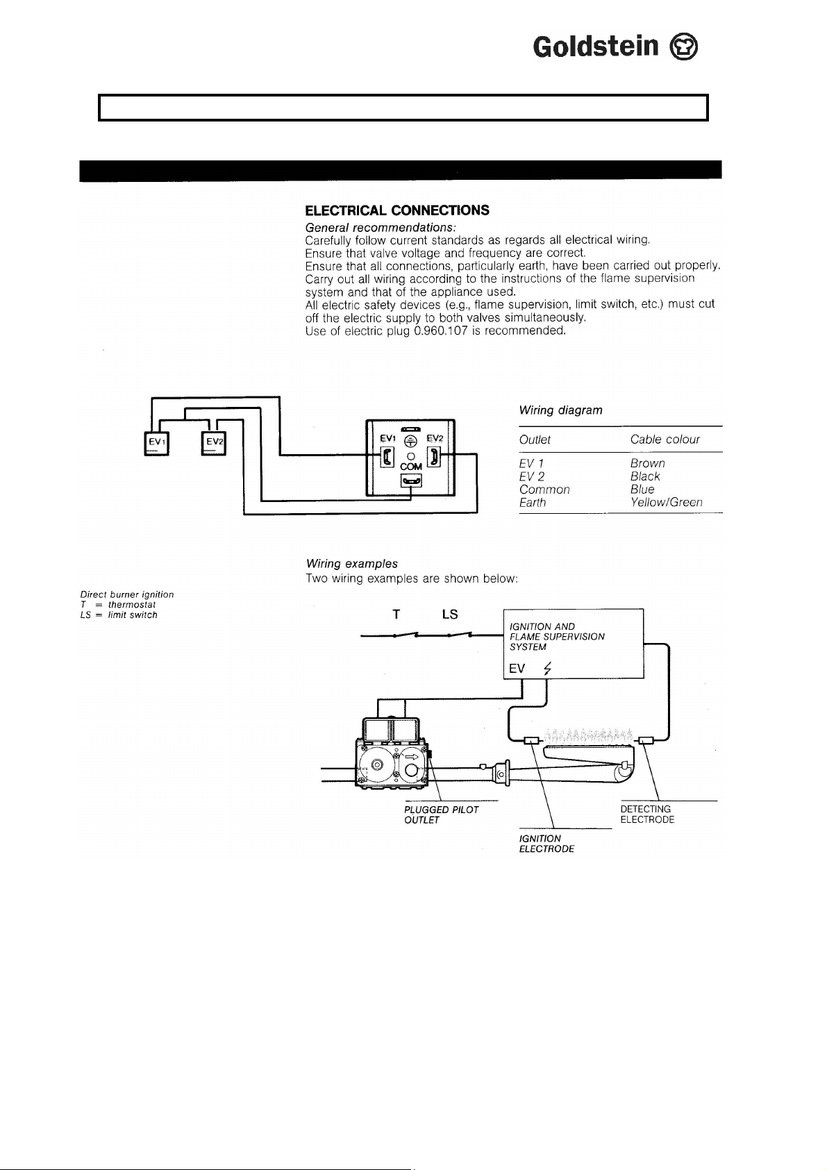
8. ELECTRICAL CONNECTION
14
IM067B2 – June 2010
Page 15

9. GUIDE FOR COOKING TIME & TEMPERATURES
This information should be used as a guide in developing your own baking and roasting
chart.
MEAT POULTRY FISH Suggested Time Suggested Your
YourTemp Time Temp
Roasting…………….. 10-15min/500g 125-300…….. ……….
Braising…………….. 20-25min/500g 150……….. ……….
Cafeteria Beef Rounds (20kg) 9 hours 120………… ……….
Steaks (1-1.2” thick) 10-14 min 225………… ……….
Meat Loaf (4-1/4”x9”)……. 45min – 1 hr 150………… ……….
Hamburger Patties……….. 4-8 min 200………… ……….
Bacon …………………….. 5-10 min 200………… ……….
Sausage Links …………… 8-12 min 200………… ……….
Turkey (11 kg)……………. 2-1/2 – 3 hrs 150………… ……….
Oven Browned Chicken Parts 40-45 min 175………… ……….
Fish Fillets (125g frozen)………. 20-25 min 230………… ……….
Fish Sticks (30g frozen) ………. 10 min 200………… ……….
BAKED PRODUCTS
Sheet Cakes 18”x26”)…………. 20 min 160………… ……….
Biscuits………………………….. 8-12 min 175………… ……….
Pie Crust………………………… 8-10 min 200………… ……….
Fruit Pies ……………………….. 30 min 180………… ……….
Custard Type Pies…………….. 30-45 min 150-160…… ……….
Meringue topping for pies…….. 8-10 min 160………… ……….
Scones …………………………. 8-10 min 175-200…… ……….
Muffins …………………………. 12-15 min 150………… ……….
Danish Rolls ………………….. 10 min 175………… ……….
Hamburger Buns ……………… 20 min 160………… ……….
MISCELLANEOUS PRODUCTS
Baked Potatoes (250g) ……….. 45-60 min 225………… ……….
Toasted Cheese Sandwiches … 8-10 min 175………… ……….
Casseroles (12”x20”x2” pan)….. 20 min 175………… ……….
Casseroles (12”x20”x4” pan)… 30 min 130 ……….
Rice, covered
(1-1/2kg per 12”x20”x2” pan) 30 min 160……………….
FROZEN FOOD PRODUCTS
Fruit Pies …………………………. 30 min 200 ……….
Pot Pies individual……………….. 20-30 min 200 ……….
Casseroles, covered (12”x20”x2”) 45 min 200 ……….
Casseroles refrigerator thawed
(12”x20”x2” pan) ……………… 30 min 225 ……….
Dinners individual covered…… 10-15 min 225………………….
Vegetables covered
(2-1/4 kgs per 12”x20”x2” pan) 20-30 min 200 ……….
IM067B2/p15
15
IM067B2 – June 2010
Page 16

10. CLEANING INSTRUCTIONS
CLEANING/MAINTENANCE
1. Ensure all parts are cold before handling.
2. Clean inside Stainless Steel with a liquid cleaner. Use scotch-brite pads.
NEVER USE STEEL WOOL on any parts of the unit. Clean with the grain
of the Stainless Steel.
3. Wipe regularly with a dry cloth all grease that accumulates on the sides of
the chamber and body. This will minimise smoke and damage of flare up
during cooking.
Use a mild cleaner, CAUSTIC cleaners ARE NOT TO BE USED, otherwise
warranty will be void.
When cleaning the stainless steel surface under NO circumstances should wool
brushes or scraping implements of common steel be used on the stainless steel
because ferrous particles can deposit on the stainless steel surface causing by
their oxidation, rust spots.
Scotchbrite can also be used but it is necessary to always rub the surfaces in the
direction of the stainless steel finish.
Note
IF CAUSTIC SODA BASED OVEN CLEANERS ARE USED WARRANTY
IS VOID.
IM008B1/p16
16
IM067B2 – June 2010
Page 17

10. CLEANING INSTRUCTIONS
REMOVAL AND REPLACEMENT PARTS
1. BLOWER WHEEL REMOVAL
Remove the baffle by lifting up to free from keyhole slots.
2. BLOWER WHEEL REPLACEMENT
3. MOTOR REMOVAL
Shut off main power supply.
Remove baffle (fan cover) from oven compartment.
Grasp blower and tip forward into oven compartment.
4. MOTOR LUBRICATION
None required, motor is self-lubricating.
5. MOTOR REPLACEMENT
Follow step in No.3 in reverse.
6. MICRO-SWITCH REMOVAL
Shut off main power supply.
7. MICRO-SWITCH REPLACEMENT
Follow steps in No.6 in reverse order.
8. ELECTRIC CONTROL REMOVAL
Shut off main power supply.
Disconnect wires from whichever control shall be removed.
Remove control panel by removing screw.
Blower switch.
IM067B2/p17
Shut off main power supply.
Loosen the 2 allen-set screws on the wheel hub with 4/32” allen
key.Use wheel puller if the blower wheel does not come off readily.
Lubricate blower wheel hub with high temperature compound or
graphite grease.Tighten allen set screws firmly and replace baffle.
Remove the 4 nuts around the blower wheel from the motor mount
panel with ½” wrench.
With motor and panel inside, remove cover plate in rear of motor
and disconnect wires.
Remove top nosing trim (4 screws) and disconnect wires from
micro-switch (top RHS of oven).
Undo nut holding micro switch.
Remove micro switch from housing.
Adjust screw if necessary. Micro-switch should be activated when
right hand door is about 50mm open.
17
IM067B2 – June 2010
Page 18

11. PROBLEM SOLVING
1. Wide Variation of results in cooking.
(a) Cause: Remedy
Fluctuating gas pressure. Fit or adjust governor.
2. Pilot outage
Fluctuating pressure. Fit or adjust governor.
(b) Cause: Remedy
Contamination of pilot orifice. Clean pilot orifice.
(c) Cause: Remedy
(d) Cause: Remedy
Defective thermocouple Replace.
(e) Cause: Remedy
Defective safety shut-off valve. Replace.
3. Burner goes out and flashes back
Excessive aeration.) Refer to Servicing
4. Yellow Flame
(a) Cause ) Remedy
IM067B2/p18
(a) Cause: Remedy
May need gas company or
Plumber to check gas
supply
Extreme over-gassing of main Check burner jet orifice
Burners. Governor adjustment.
(a) Cause Remedy
Instructions and adjust.
Too much gas to burner. ) Check gas pressure and
) burner Jet orifice.
18
IM067B2 – June 2010
Page 19

11. PROBLEM SOLVING
CAUSE AND REMEDY FOR DEFECTIVE OVEN COOKING
1. Too much bottom heat, which results in burning on the bottom of
baked products also scorching on the sides. Products will be too
light on top, uneven in colour on the top and probably raw in the
centre.
(a) Cause: Remedy
Insufficient (BTU) MJ input. Check line or for blockage
and clear
(b) Cause: Remedy
Overactive flue Check that baffles, if fitted
are in place.
(c) Cause: Remedy
Thermostat calibration set too low. Re-calibrate
2. Too much top heat, which results in Dark top of baked products and
light bottom, possibly not baked in centre.
(a) Cause: Remedy
Excessive (BTU) MJ input. Check burner injector
orifice for correct size also
check governor pressure.
(b) Cause: Remedy
Under active flue or flue restriction. Check for obstruction in
flue way.
(c) Cause: Remedy
Thermostat calibration too high. Re-calibrate
3. Uneven baking characteristics from side to side.
(a) Cause: Remedy
Oven burner out of alignment Locate burner on level
flame.
of flue.
(b) Cause: Remedy
Appliance not level side to side. Level appliance with spirit
level.
(c) Cause: Remedy
Burner baffle (if fitted) tilted causing Replace baffle.
Products of combustion to be
directed to one side.
19
IM067B2 – June 2010
Page 20

11. PROBLEM SOLVING
4. Baking characteristics from front to back.
(a) Cause: Remedy
Over-active flue Check that baffles, if fitted
are in place.
(b) Cause: Remedy
Unit not level, front to back Using spirit from front to
back, level up appliance by
means of adjustable feet.
5. Dried out Product
(c) Cause: Remedy
Too low a temperature. Adjust thermostat
accordingly.
(b) Cause: Remedy
Too long a baking time. Adjust cooking time and
temperature to suit
product.
Check gas pressure.
20
IM067B2 – June 2010
Page 21
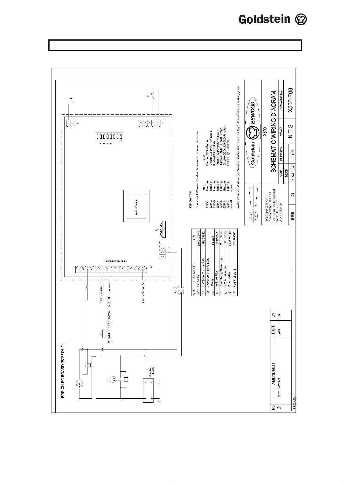
12. WIRING DIAGRAM
21
IM067B2 – June 2010
Page 22
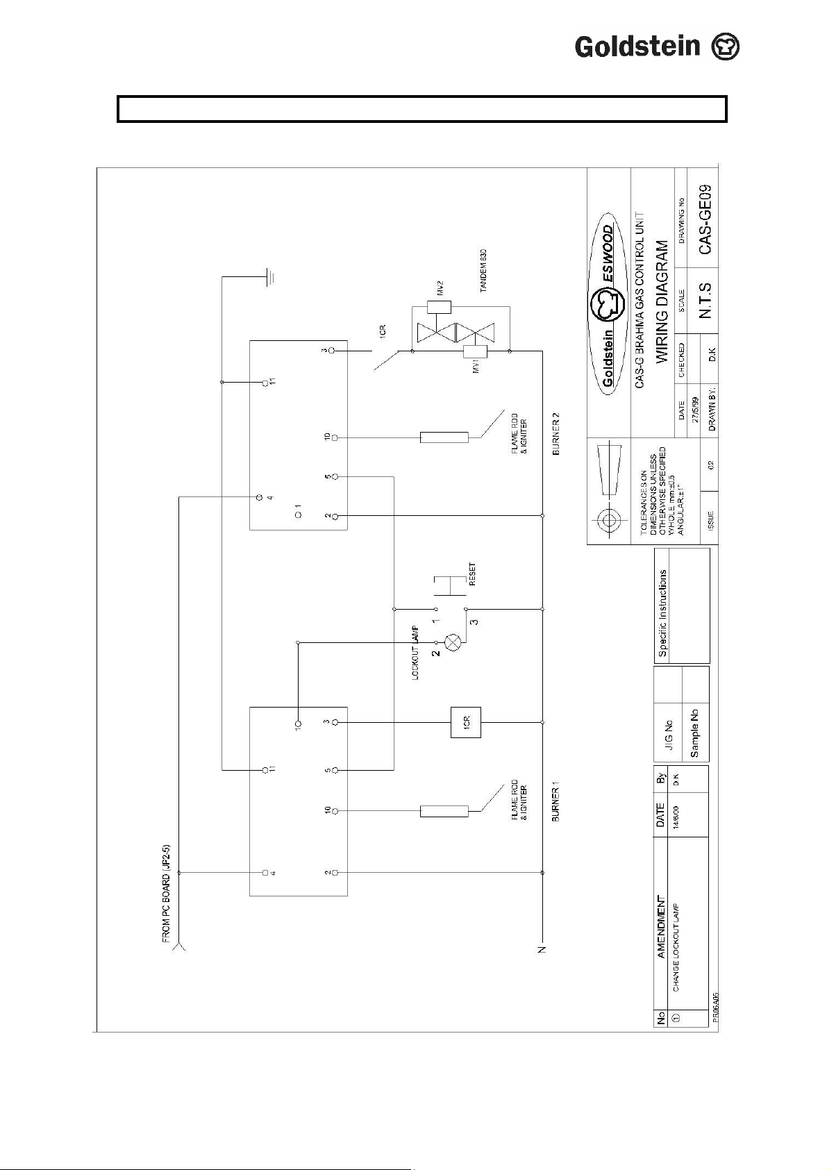
12. WIRING DIAGRAM
22
IM067B2 – June 2010
Page 23
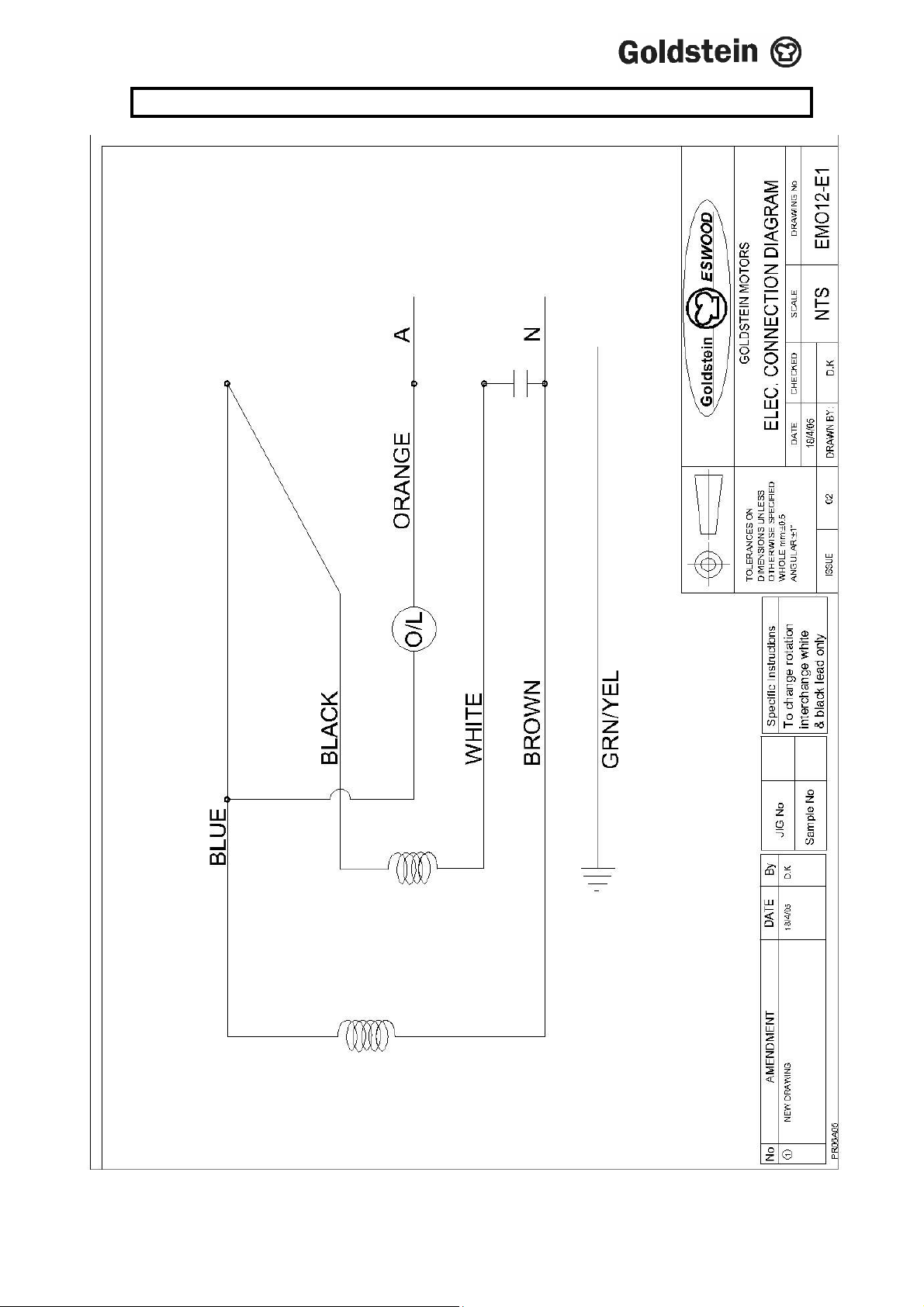
13. CONNECTION DIAGRAM
23
IM067B2 – June 2010
Page 24
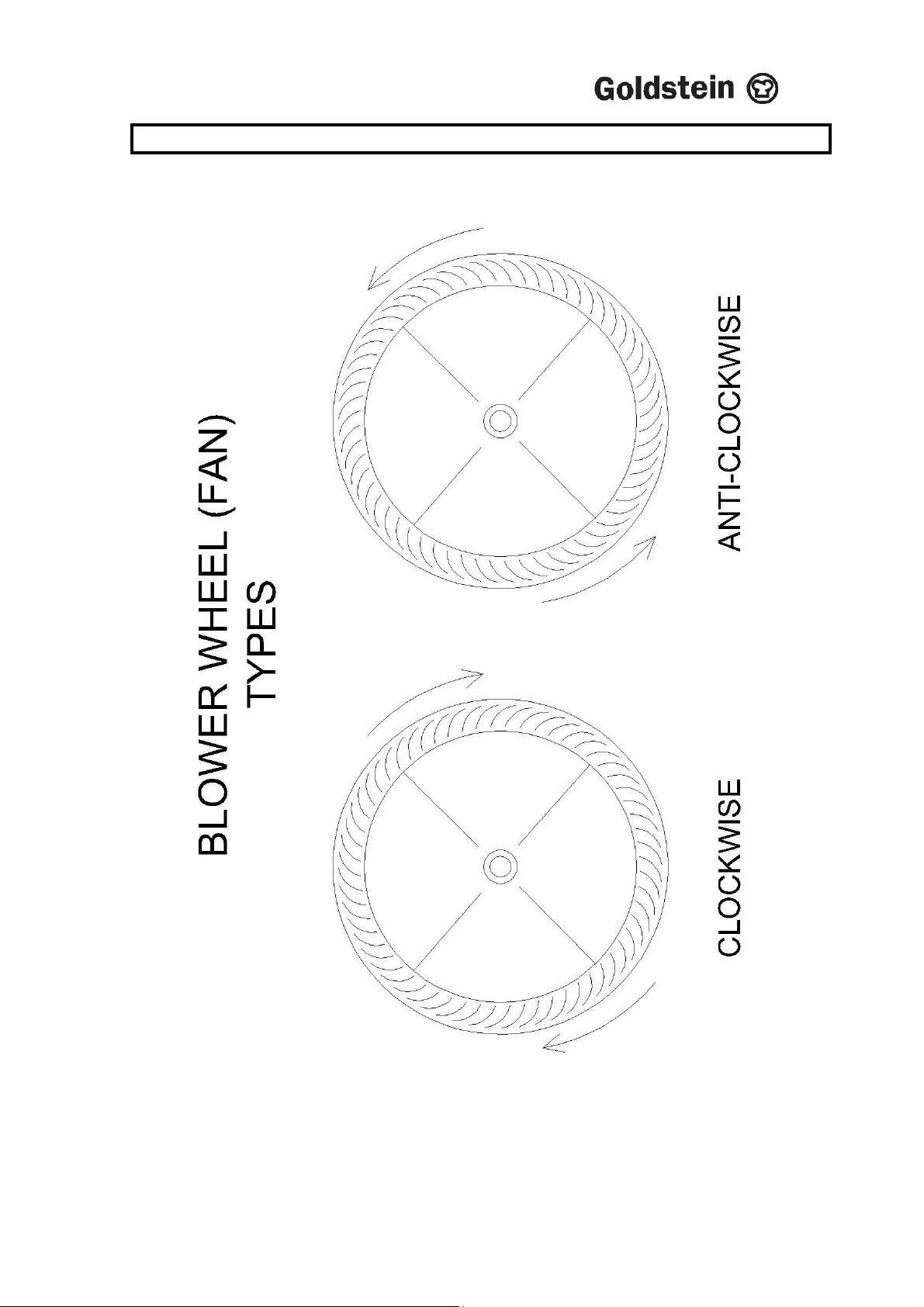
14. BLOWER WHEEL FAN
24
IM067B2 – June 2010
Page 25
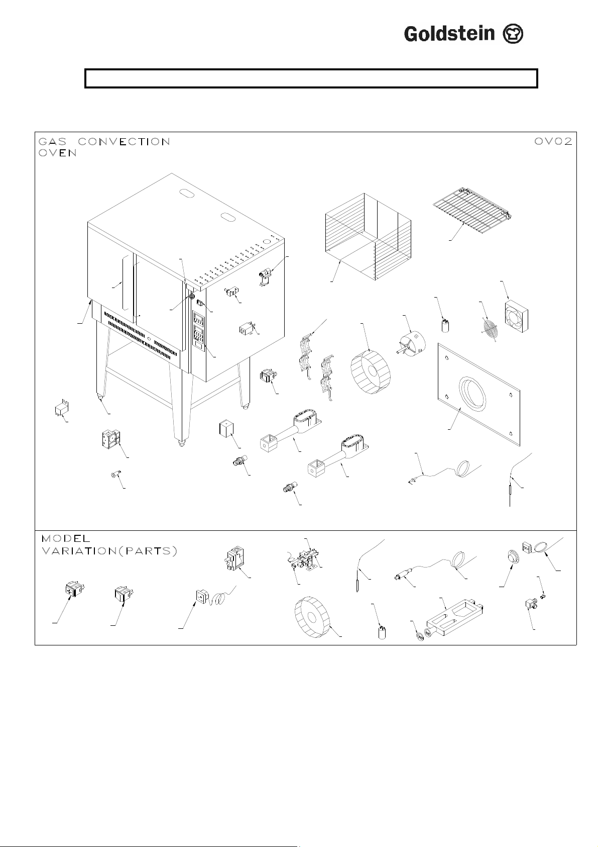
15. DRAWINGS
MODEL: X500 A
1
9
14
36
24
19
37
13
12
22
21
10
38
2
9
7
8
11
7
18
17
30
27
17
29
16
28
20
4
16
40
39
5
31
6
3
15
32
41
42
33
26
34
25
23
43
35
44
25
IM067B2 – June 2010
Page 26

15. SPARE PARTS
MODEL: X500 A
ITEM No. CODE DESCRIPTION
1. X500-M03 TRAY
2. X500-M01 CASSETTE
3. X500-A13 FAN PANEL ASSEMBLY
4. MFA00012 BLOWER WHEEL
5. EMO120W0 MOTOR
6. ECA00002 6 MF CAPACITOR
7. ESW00007 MAIN SWITCH
8. MRL00002 FILTER
9. ESWM0006 MICRO SAFETY SWITCH
10. MKNPL020 KNOB
11. ECPSTH01 PC BOARD
12. MLESSBF1 FEET S/S
13. PF-24M14 S/S HANDLE
14. MSN10V00 SOLENOID
15. GPIC0011 ELECTRODE WITH LEAD
16. GBNCAS01 BURNER
17. GIJGP170 INJECTOR – 1.70mm L/P
17. GIJGP265 INJECTOR – 2.60mm N/G
18. ECPGASG1 BRAHMA BOX
19. ECT00005 RELAY
20. X500BP02 TUNNEL DISPENSER
21. GCUCASG0 CONTROL 830
22. ESW00031 ROUND SWITCH
23. ETCK1500 K. THERMOCOUPLE
24. MGK00009 DOOR GASKET
25. MFA00007 FAN
26. MFG00001 FINGER GUARD
27. GCU0X500 GAS CONTROL 820
28. GPIC0003 ELECTRODE
29. GPI00002 2WAY PILOT
30. GTC01000 THERMOCOUPLE – L=1000
31. ETCK0000 THERMOCOUPLE – K TYPE
32. ESP00003 SPARKER
33. ESPL0650 SPARKER LEAD – 650mm
34. MKNPLT10 KNOB – 60 – 288
35. MTH00288 THERMOSTAT
36. ESWS30W0 3 WAY SWITCH
37. ESW520B0 2 WAY SWITCH
38. ETMS3000 TIMER – 240V AC 5HR
39. MFA00003 FAN BLOWER 10” SV 200X
41. GBNX500 BURNER
42. PF-00P33 AIR INLET
43. GIJTP400 INJECTOR – X500A 4.mm N/G
43. GIJTP225 INJECTOR – X500A G236 2.25mm L/P
44. GIJTPH00 INJECTOR HOLDER GIFTP##
26
IM067B2 – June 2010
Page 27

17. WARRANTY
Installation must be carried out according to local regulations by qualified trade
persons.
Isolating switch(es), shut-off valves etc must be within easy reach of the machine
for future service and maintenance requirements.
If in doubt call GOLDSTEIN/ESWOOD or their representative for further
information. No responsibility will be accepted for defects or damages by
improper installation, for changes to the product not authorised by
GOLDSTEIN/ESWOOD or for operation outside the technical specifications.
GOLDSTEIN/ESWOOD warrants their products to be free from defects in
material and workmanship under “normal use and service”. This does not
include normal wear and tear of parts. GOLDSTEIN/ESWOOD will repair or
replace any parts, which in GOLDSTEIN/ESWOOD’s sole judgement are
defective in material or workmanship, in accordance with the warranty offered.
This undertaking covers the provision of labour and parts for 12 months from the
date of delivery to the purchaser. This undertaking applies only to state capitals.
Remote areas are not covered by this commitment and special enquiries should
be made. (Note: Travel time not covered by warranty).
“To the maximum extent permitted by law, any liability on Goldstein/Eswood’s
part or on the part of its servants or agents for loss or damage of any kind
whatsoever in connection with the products, including liability for or in respect of
any claim arising out of contract, negligence or statute, shall not, in any event,
exceed $100”
Labour under warranty is supplied free of charge during normal working hours,
Monday to Friday. Should warranty work be requested outside of our normal
working hours a labour charge will be applied equivalent to a normal hour rate,
without out of hours penalty rates. (Refer to last page of this manual for your
closest branch for warranty repair services).
FAILURE TO DO SO WILL VOID
WARRANTY ON THE EQUIPMENT
PLEASE RETURN YOUR WARRANTY CARD
NOTICE
27
IM067B2 – June 2010
Page 28

18. GOLDSTEIN/ESWOOD BRANCHES
For inquiries please call your nearest state branch:
Head Office
211-213 Woodpark Road
Smithfield New South Wales 2164
Phone: 02 9604 7333
Fax: 02 9604 5420
Victoria Queensland
47 Stubbs Rd Nautilus Complex
Kensington Unit 12
Victoria 3031 210 Queensport Road
Murrarie Qld 4172
Phone: 03 9372 6477 Phone: 07 3890 1811
Fax: 03 9372 6577 Fax: 07 3890 1788
South Australia Western Australia
Suite 26 Unit 1/10 Wittenberg Drive
283-287 Sir Donald Bradman Drive Canning Vale
Brooklyn Park South Australia 5032 Western Australia 6155
Phone: 08 8238 3423 Phone: 08 9456 0559
Fax: 08 8238 3400 Fax: 08 9456 0554
28
IM067B2 – June 2010
 Loading...