

goldstein PF-8-40, PF-6-12G-40, PF-2-36G-40, PF-4-24G-40, PF-48G-40 Installation Procedures Manual

The Heavyweight 800 Series Performance Plus
And Fan Forced Units
PROUDLY AUSTRALIAN MADE
INSTALLATION PROCEDURE – USER MANUAL
SERVICE INSTRUCTION
MODELS PF-8-40, PF-6-12G-40, PF-2-36G-40, PF-4-24G-40, PF-48G-40
FAN FORCED
FAN
FORCED
GAS APPROVAL NO. 2597
ESTABLISHED 1911
The Cooking Equipment Professionals
www.goldsteineswood.com.au

TABLE OF CONTENTS
1. INTRODUCTION Page 3
2.INSTALLATION Page 4
3.COMMISSIONING Page 5
4. MAINTENANCE Page 6
5.TRIVETS Page 7
6. PILOT & BURNER OPERATION Page 8
7.CONTROL Page 9
8. THERMOSTAT SETTING Page 10-11
9.PROBLEMSOLVING Page 12-13-14
10.FANFORCECONTROL Page 15
11. FAN FORCE WIRING DIAGRAM Page 16
12. DRAWING Page 17
13.SPAREPARTS Page 18&19
14. WARRANTY Page 20
15. BRANCHES Page 21
IM037B1/p2

1. INTRODUCTION
Congratulations for purchasing your Goldstein commercial cooking
appliance.
J. Goldstein & Co. is a wholly owned Australian company and has been
operating since 1911, building high quality products. The information in
this manual will assist your installer and ensure correct location and
connection. Thoroughly read the user instructions and the user
maintenance sections, as understanding your products, its operation,
and its cleaning and service requirements will provide you with long and
satisfactory service. Failure to do so could shorten the life of the product
and decrease its efficiency. Please ensure only authorised service
technicians are called to any difficulties that may arise.
INTRODUCTION
GOLDSTEIN HEAVYWEIGHT 800 SERIES PERFORMANCE PLUS &
FAN FORCED UNITS – CONVECTION OVEN
MODELS PF-8-40, PF-6-12G-40, PF-2-36G-40, PF-4-24G-40, PF-48G-40
GOLDSTEIN RANGES designed to give long and satisfactory service and
incorporate the best possible materials and workmanship. Proper installation,
adjustment and preventative maintenance are vitally important if efficiency
and appearance are to be maintained.
Read these instructions carefully as they contain important safety information
regarding the installation, use and maintenance of the appliance.
RECEIVING INSPECTION
x
Check crates for handling damage. After carefully uncrating, check for
“concealed” damage. Report any damage immediately to carrier and to dealer.
x
Remove check all loose items from unit and check contents as found on back of
warranty cards.
x
Check type and capacity of gas supply.
x
The type of gas for which this 800 Series is factory adjusted can be seen on the
rating plate, located on the bottom front panel of the Range.
NOTICE
PLEASE RETURN YOUR WARRANTY CARD
FAILURE TO DO SO WILL VOID WARRANTY
ON THE EQUIPMENT
IM037B1/p3

2. INSTALLATION
INSTALLATION
Please follow these instructions carefully
All equipment must be sitting level for proper operation and combustion where plinth
type installation is made, plinth height and front overhang must be 50 mm minimum.
Levelling can be made by the use of metal shims. For performer series where
adjustable legs are provided, levelling can be made easily due to the threaded
construction of the legs.
Connection to main gas line should be made by licensed Gasfitter. Install a hand
shut-off valve in gas line to the appliance manifold and also on Natural Gas only.
Ventilation
Adequate ventilation must be provided, preferably by a hood with vent and
exhaust fan. Never make a direct connection between the flue of the
appliance and the vent flue. Refer AS 5601/AG601 Gas Installation Code.
INSTALLATION
NOTE: The appliance must be installed by an authorised person and in
accordance with the regulations of the local Gas Authority,
AS5601/AG601 and any other authority having jurisdiction. The
appliance has been tested and preset before leaving our factory, but
small adjustments may be necessary to suit local conditions.
Correct operation of the appliance must be tested as part of the
installation procedure.
NOTE: Models operating on LP Gas will be supplied with a regulator as from
(1
st
January 2005) as new standard (AS4563/AG300).
LIGHTING INSTRUCTIONS
1. All range and roast ovens are complete with instructions on a Decal Front
Control Panel attached to the appliance on the front stainless fascia.
2. Range top arrangement:
A. All open burners may be ignited by the constant pilots.-Manually
B. Griddle top and hot top sections are provided with flame failure device gas
cocks Model 21S and is ignited by Piezo ignition.
ADJUSTMENT
Adjustments to burners and burner pilots can be made when necessary by any
qualified service organisation or your local gas utility service department.
IM037B1/p4

3. COMMISSIONING
COMMISSIONING APPLIANCE – DETAILS, TESTING, CHECKING PRESSURE
ETC.
COMMISSIONING CHECK LIST
1. CHECK FOR DAMAGE AND MISSING PORTS.
2. REMOVE ALL PLASTIC COATING FROM S/STEEL PANELS.
3. MAKE SURE ALL PARTS ARE IN THEIR CORRECT POSITION E.G.
TRAYS BURNERS KNOBS.
4. MAKE SURE ALL ELECTRIC AND GAS CONNECTIONS ARE CORRECT
AND TIGHT.
5. LEVEL OFF UNIT LEFT TO RIGHT AND ALSO MAKE SURE THAT FRONT
IS JUST 3-4 MM LOWER TO ALLOW FOR FLUING.
6. TURN ON GAS OR ELECTRICITY.
7. ADJUST GAS PRESSURE WITH THREE-QUARTERS OF THE UNIT
RUNNING, ADJUST GAS PRESSURE.
NATURAL GAS 1.00 KPA
LPG 2.75 KPA
8. TURN ON ONE AT A TIME TO MAKE SURE ALL IS WORKING E.G.
BURNER, RADIANT, GRIDDLE AND OVEN.
9. SHOW CUSTOMER
A) HOW TO WORK EQUIPMENT
B) HOW TO CLEAN
C) HOW TO PULL IT APART E.G. TRAYS, TRIVETS.
D) ALSO WHAT NOT TO DO, E.G. WATER WITH ELECTRICAL,
GREASE AND OIL IN CONTROLS.
10. CHECK TO MAKE SURE MANUALS AND WARRANTY CARDS ARE
THERE.
ALSO GO THROUGH MANUAL WITH CUSTOMER E.G. LIGHTING,
CLEANING.
NOTE
WASH HOSES SHOULD NEVER BE USED ON THE APPLIANCE.
USE OF HOSES WILL VOID WARRANTY
IM037B1/p5

4. MAINTENANCE
MAINTENANCE PROCEDURE
USE PROTECTIVE CLOTHING FOR CLEANING TO AVOID DANGEROUS
CONTACT WITH HOT SURFACES.
1. CAST IRON TRIVET
Wash in WARM soapy water, use Plastic Scourer if necessary. Dry with soft
cloth or paper towel.
2. STEEL GRIDDLE PLATES, ALL RANGES & GRIDDLE UNITS
To clean steel griddle plates, wash with cold water and cleanser while the
plate is Hot. Use wire brush to remove accumulations or hardened grease
around splashand gutter. Wipe clean of water and oil lightly over surface.
NB EMPTY THE WASTE GREASE CAN BEFORE WASHING DOWN
3. RANGE OVENS
The interior surfaces of the oven are porcelain enamel and can be cleaned
with soap and hot water or any approved oven cleaner. The base and two
sides are removable.
4. HOT TOP PLATES (Target Top)
A. Burner under the hot top section should be turned on low for the initial
breaking-in. Gradually increase the heat for approximately six hours
until maximum temperature for heavy duty cooking has been reached.
B. Care of top plate should be limited to periodic wiping off with rough
cloth or burlap.
5. STAINLESS STEEL
Using a liquid cleaner indicated especially for this type metal can clean the
stainless steel finish. NEVER attempt to clean stainless steel with steel wool,
abrasive cloth or powders.
6. PERIODIC CLEANING.
Keep grease, spillovers and other accumulations out of both top and oven
burner boxes or areas. The exterior painted surface of all appliances can be
cleaned with warm water and soap or a mild detergent. Removable drip or
grease pans are easily cleaned with warm water and soap or a mild
detergent.
OPERATIONAL PROBLEMS AND SERVICE
No service is anticipated. However, should the occasion arise that service is
required, call a qualified gas service organisation or your local gas utility service
department
DO NOT USE STEEL WOOL, ABRASIVE CLOTHS, CLEANSERS OR POWDERS!
If it is necessary to scrape stainless steel to remove encrusted materials, soak the
area with hot cloths to loosen the material, and then use a wood or nylon scraper.
DO NOT USE a metal knife, spatula, or any other metal tool to scrape stainless
Steel. Scratches are almost impossible to remove
IM037B1/p6
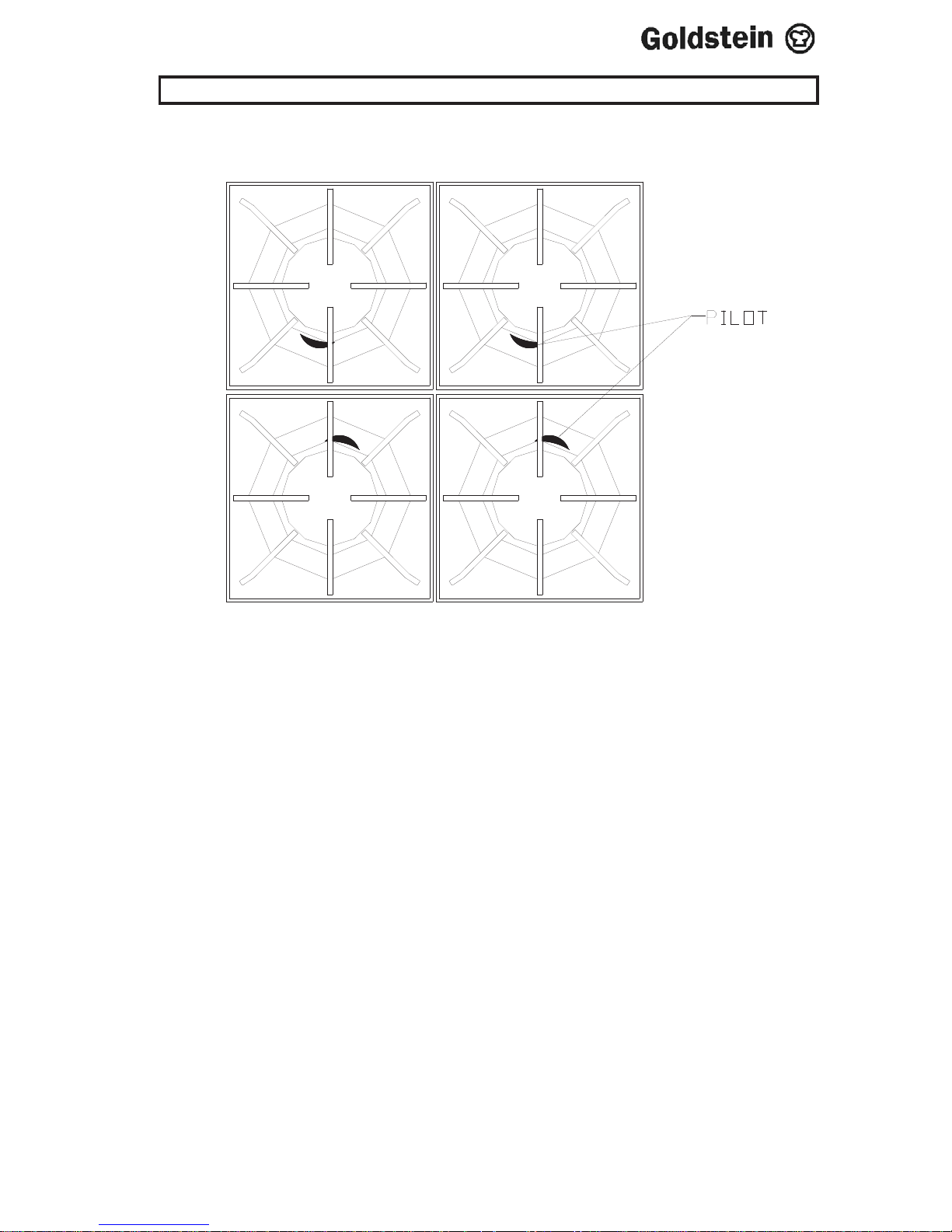
5. TRIVETS
ENSURE ALL TRIVETS ARE PUT ON AS PER DIAGRAM ABOVE, SO
THAT THE PILOTS ARE UNDER THE CANOPIES.
FAILURE TO PLACE TRIVETS CORRECTLY MAY CAUSE A FIRE
HAZARD.
IM037B1/p7
 Loading...