

goldstein GPG-30, GPG-45, GPGDB-12, GPGDB-24, GPGDB/SA-24 Installation Procedure – User Manual Service Instruction
...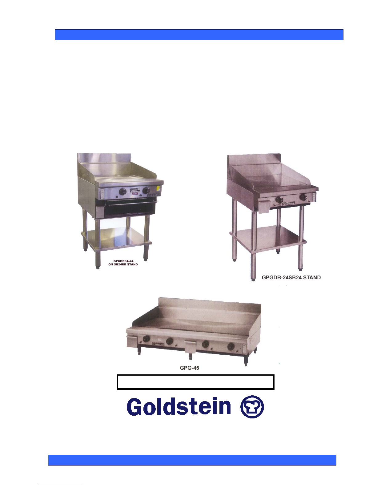
GAS GRIDDLE & COMBINATION GRILL AND
SALAMANDER TOASTER
PROUDLY AUSTRALIAN MADE
INSTALLATION PROCEDURE – USER MANUAL
SERVICE INSTRUCTION
MODELS GPG-30, GPG-45, GPGDB-12,24,36,48,
GPGDB/SA-24,36
GAS APPROVAL NO. 6006 & 6215
ESTABLISHED 1911
The Cooking Equipment Professionals
www.goldsteineswood.com.au

TABLE OF CONTENTS
1. INTRODUCTION Page 3
2. INSTALLATION Page 4
3. COMMISSIONING Page 5
4. OPERATING INSTRUCTIONS Page 6 & 7
5. LIGHTING INSTRUCTIONS Page 8
6. TECHNICAL INSTRUCTIONS Page 9
7. TECHNICAL DATA Page 10 & 11
8. CLEANING INSTRUCTIONS Page 12
9. PROBLEM SOLVING Page 13, 14 & 15
10. DRAWINGS - SPARE PARTS GPG-30,45 Page 16 & 17
11. DRAWINGS - SPARE PARTS- GPGDB/ SA-24,36Page 18 & 19
12. WARRANTY Page 20
13. BRANCHES Page 21
IM027B2/p2

1. INTRODUCTION
Congratulations for purchasing your Goldstein commercial cooking appliance.
J. Goldstein & Co. is a wholly owned Australian company and has been
operating since 1911, building high quality products. The information in this
manual will assist your installer and ensure correct location and connection.
Thoroughly read the user instructions and the user maintenance sections, as
understanding your products, its operation, and its cleaning and service
requirements will provide you with long and satisfactory service. Failure to do
so could shorten the life of the product and decrease its efficiency. Please
ensure only authorised service technicians are called to any difficulties that may
arise.
INTRODUCTION
GOLDSTEIN GAS GRIDDLE & COMBINATION GRILL AND
SALAMANDER TOASTER
MODELS GPG-30, GPG-45,GPGDB-12-24-36-48, GPGDB/SA-24,36
GOLDSTEIN GRIDDLES are designed to give long and satisfactory service and
incorporate the best possible materials and workmanship. Proper installation,
adjustment and preventative maintenance are vitally important if efficiency and
appearance are to be maintained.
Read these instructions carefully as they contain important safety information
regarding the installation, use and maintenance of the appliance.
RECEIVING INSPECTION
•
Check crates for handling damage. After carefully uncrating, check for “concealed”
damage. Report any damage immediately to carrier and to dealer.
•
Remove check all loose items from unit and check contents as found on back of
warranty cards.
•
Check type and capacity of gas supply.
•
The type of gas for which this Griddle is factory adjusted can be seen on the rating
plate, located on the front Control Panel.
“THE EQUIPMENT MUST BE INSTALLED BY A
LICENSED GASFITTER
Note The appliance must be installed by an Authorised person and in accordance with
the regulations of the local Gas Authority AS5601/AG601 and any other authority
having jurisdiction.
IM027B2/p3

2. INSTALLATION INSTRUCTIONS
PRE-INSTALLATION OF THE GRIDDLE
1. Check that there is sufficient clearance between doors and passageways to
move equipment into the cooking area.
2. Remove banding and cardboard outer.
3. Lift off wooden base.
4. Push in legs and tap in with a hammer into tubes (If required mount on stand
(OPTIONAL)
INSTALLATION
(FOR AUTHORISED TECHNICIANS ONLY)
Note: AFTER ANY MAINTENANCE OR ADJUSTING OF GAS CONNECTED
COMPONENTS, A GAS LEAK TEST MUST BE CARRIED OUT, TO ENSURE
THERE ARE NO GAS LEAKING HAZARDS
Adequate ventilation must be provided by a hood with vent and exhaust fan. Never
make a direct connection between the unit and vent flue. Check there is sufficient
room between doors and other units to allow equipment to be moved into position.
Check the data plate to ensure that the appliance is suitable for the gas supply to
which it is to be connected and for information relative to gas input. Etc.
Follow these instructions carefully.
1. Set unit in correct position (ENSURE THERE IS A MIN 25mm REAR WALL
CLEARANCE FROM COMBUSTIBLE MATERIALS AND THAT THE UNIT IS
PLACED ON A FIRE PROOF BASE) and adjust feet using a spirit level,
checking from back to front and side to side.
2 Have a licensed gas fitter or our local gas company connect the appliance to the
mains pressure supply. The gas inlet connection can be seen in the appendix.
The appliance must be installed in accordance with rules of any authority having
jurisdiction. The governor supplied must be installed on the gas inlet to the
appliance. This is supplied as a loose item.
3. All equipment must be sitting level for proper operation and combustion where
plinth type installation is made, plinth height and front overhang must be 50 mm
minimum. Levelling can be made by the use of metal shims. For griddles where
adjustable legs are provided, levelling can be made easily due to the threaded
construction of the legs.
Licensed plumber should make connection to main gas line. Install a hand
shut-off valve in gas line to the appliance manifold.
NOTE: Models operating on LP Gas are not supplied with a governor because none is
required.
WARNING
”DO NOT SPRAY AEROSOLS IN THE VICINITY OF THIS APPLIANCE WHILE IT IS
IN OPERATION”
IM027B2/p4

3. COMMISSIONING INSTRUCTIONS
OPERATION
(FOR AUTHORISED TECHNICIANS ONLY)
Note: All the appliances that leave our factory have been tested and adjusted
according to the specifications for the required gas. The regulator may have to
be adjusted to achieve the required gas pressure
Note: Before igniting the griddle plate, remove the protective coating on the
plate with solvent (e.g. mentholated spirits).
After installation of the appliance the installer should light all burners to ensure that
they are operating correctly. The burner flames should not have yellow tips nor should
they be too “hard”. The aeration of each Burner can be adjusted by altering the
position of the shutter on the entrance to the throat of the Burner. Note GPGD/SA has
an adjustable bolt on the bottom of the Burner
If the appliance cannot be adjusted correctly for satisfactory operation, the matter
should be referred to the manufacturer or the local gas supply authority.
Ensure that the pressure at the pressure test point on the manifold is as per the rating
plate or as per page – of this manual. If the pressure is not the same use a
screwdriver to adjust the pressure regulator (turning screw clockwise will increase the
pressure).
Turn the control knob to low and check that the flame size has decreased substantially.
If flame has not decreased, then using a small flat headed screwdriver adjust the “min
gas screw” on the front of the gas control until the min flame gets to desired size
(turning screw clockwise will decrease the flame size).
Turn the griddle plate off and apply a coating of cooking oil to the whole griddle plate
surface. Failure to do this will cause the warranty to be void.
NOTE
WASH HOSES SHOULD NEVER BE USED ON THE APPLIANCE.
USE OF HOSES WILL VOID WARRANTY
NOTICE
PLEASE RETURN YOUR WARRANTY CARD
FAILURE TO DO SO WILL VOID
WARRANTY ON THE EQUIPMENT
IM027B2/p5
4. OPERATING INSTRUCTIONS
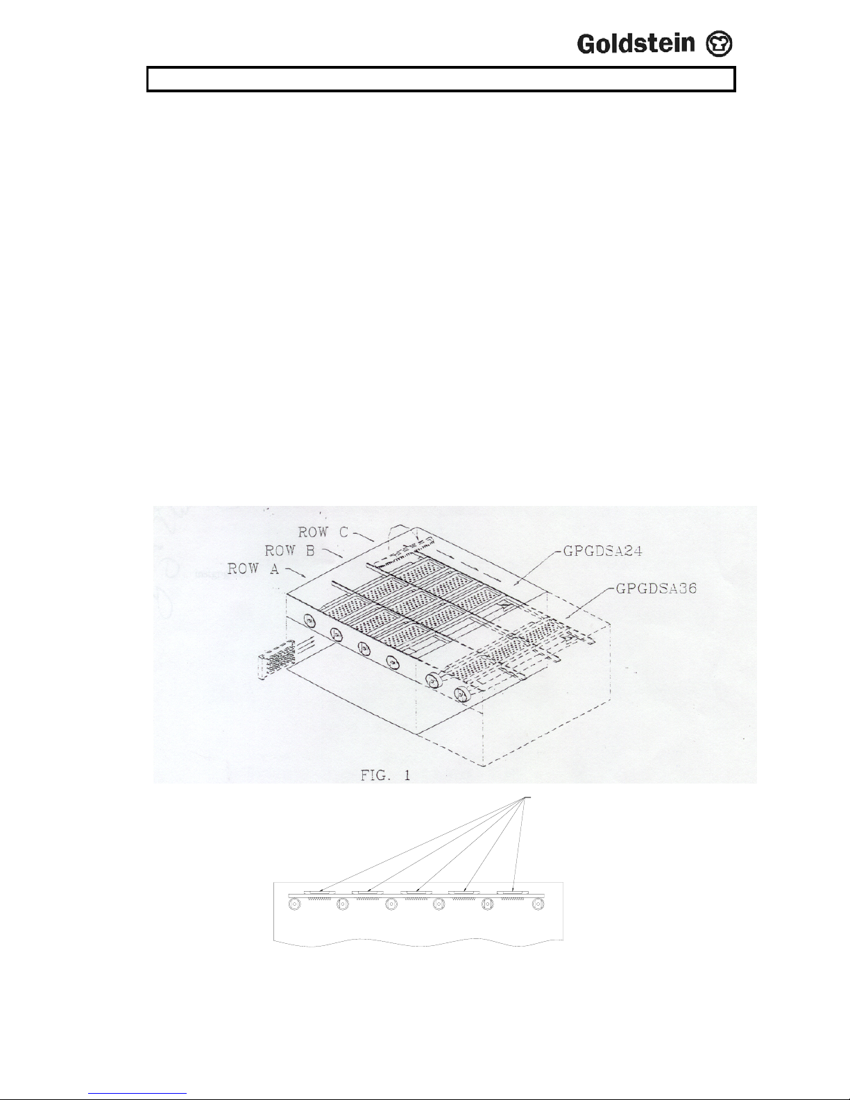
INSTALLING FRETS INTO THE GPGDSA
This procedure is to be followed after the unit has been mounted into desired position.
Note To avoid damage to frets only insert them into a row from the left hand side.
Note The first fret that you put into each row should be the far right hand fret. All
other frets follow, so that the frets are put into position from the right to the left.
Step 1 Turn fret onto its side with points facing to the right (refer Fig 1)>
Step 2 Holding the fret in your left hand move to below the left hand side of the
desired row (refer Fig 1)
Step 3 Lift fret up between the left hand burner and the side of the unit. Tilting fret
slightly, slide fret onto rails above burners, ensuring that the fret has the points
facing down (refer Fig 1).
Step 4Using your right and your left hand in conjunction, slide the fret to the right
hand side. The first fret that you put into each row should be the right hand fret,
which will be positioned above the space between the 2 far right burners. The
next fret put into the row should be positioned in the space to the left of the
previous fret. This should be repeated until the specified amount of frets are put
into each row. (Refer Fig.2).
Note Each fret should be located above the space between each burner:
For the GPGDSA-24 there will be 3 frets in each row.
For the GPGDSA-36 there will be 5 frets in each row.
Frets to be
placed points down
FRONT VIEW
FIG.2
IM027B2/p6

5. LIGHTING INSTRUCTIONS
A
Q
Q
OFF
B
PILOT
XC
S
MAX
X D S
MIN
Q
ÎSPARKER TO LIGHT PILOT
G
A= OFF
B= IGNITION POSITION – LIGHT PILOT – (If flame failure hold in for 10
seconds to establish pilot flame).
C= TURN TO FULL ON – MAX GAS FLOW, FURTHER ADJUSTMENT
BETWEEN POSITIONS C & D.
D= TURN TO MINIMUM FLOW – MIN. GAS FLOW TO MAINTAIN FLAME
(Adjustable to suit type of gas used.) as precise and accurate.
TO OPERATE:
Push in and turn knob to position “B”, light pilot burner and hold in for 10
seconds to establish Pilot flame, release (pilot burner should remain alight) and
turn to position “C” for full flow of gas, for minimum gas flow turn to position
“D”
(Adjustable to suit type of gas used). Further adjustment of gas flow between
position C & D.
IM027B2/p7

6. TECHNICAL INSTRUCTIONS
GAS BURNERS
12” GRIDDLE
Burners are from zinc alloy, of spear design. The front of the burner is fitted over
injector nipple and supported by the front baffle. The rear pf the burner is mounted
on to a support between the left and right hand baffles. To adjust the air ratio, loosen
screw on throat of burner and rotate the slide.
GPG-30, GPG-45, GPGDB-24, GPGDB-48
These are a heavy duty grey cast iron “H” Burner supported by the front of the
venturi at the burner the injector nipple and on the rear by a formed 18-gauge mild
steel runner. The burners protrude through to the front of the appliance to engage the
injector nipple. To adjust the air ratio, loosen screw on burner throat entrance and
rotate slide around.
SALAMANDER GRIDDLE
The griddle Salamander has long square cast iron burners, with drilled ports. An
interrupter screw is fitted immediately after the aspirator to give flame control. There
are 3 types of burners, the left hand/right hand/and the middle burner.
PILOTS
Polidoro 509f3. Gas to pilot is controlled through an injector spud. This spud needs to
be replaced when converting between L.P. and N.G. If appliance cannot be correctly
adjusted, advise the local gas authority or the appliance manufacturer.
Sit 3-way pilots are used on the GPGDSA-24/36. The needle needs to be changed for
conversion between N.G. and L.P.G. To adjust pilot flame size remove the screw
cover on the back of the pilot then adjust the screw to set the desired flame size
(turning screw clockwise will decrease the flame size).
INJECTORS
GPG 30/45
12mm hexagon brass rod 114mm long turned down to 11.0mm for 28.0mm long. The
remaining 11mm are turned down and threaded 6mm BSP. Centre drilled to 5.0mm
leaving an enclosed end 1.5 thick into which is drilled the appropriate orifice.
GPGDBSA 24,36
12mm hexagon brass rod 35.6mm long, is turned down to 11.1 for 9mm of its length.
Then threaded to ¼” B.S.P. for 9mm. Then 5.4mm of hexagonal is left for spanner
flats. Then 12mm is threaded to1/4” B.S.P.
GPGDB 24,36,48
12mm hexagon brass rod 114mm long turned down to 11.0mm for 28.0mm long. The
remaining 11mm are turned down and threaded 6mm BSP. Centre drilled to 5.0mm
leaving an enclosed end 1.5 thick into which is drilled the appropriate orifice.
12” GRIDDLE
12mm hexagonal brass rod 26mm long is turned down to 11mm for 13.5mm of its
length. Then 5.6mm of hexagonal is left for spanner flats. Then 7mm is threaded to
1/8” B.S.P.
IM027B2/p8

6. TECHNICAL INSTRUCTIONS Cont’d
REMOVAL OF BURNERS
Remove screws from front fascia and rear of griddle plate to allow plate to be removed.
Remove the bolts from the rear of the burner and in the case of the GPG and GPGD
remove the heat baffle that is mounted on top of the burner throat. Lift the rear of the
burner up to clear the back support and at the same time pushing toward the rear until
the air shutter, which is attached to the throat of the burner, clears the injector. Allow
the front of the burner to drop down and whilst still holding the back of the burner up
pull towards the front.
CONTROLS
The only controls are the PEL 21S gas valves. All are accessible after the front
stainless steel fascia is removed (refer to attached pages for instructions on using gas
controls. If controls get hard to turn, get a service man to remove the two screws at
the front of the control and put a high temperature graphite grease on the shaft.
IM027B2/p9

7. TECHNICAL DATA
INJECTOR SIZES
Conversion to other gases
GPGD24,36,48 GPG
GPGDSA24-36,60 GPGDB12
Inner Outer
N.G 2.05 2.1 1.6 1.1 2.15
L.P. 1.3 1.3 1.0 0.7 1.25
CONVERSION INSTRUCTIONS
To convert from N.G. to L.P. gas do the following:
1. Replace N.G. burner injectors with L.P. injectors (refer to table on following
page).
2 Replace pilot injectors to required size.
N.G. #32
L.P. #22
3. Disconnect regulator from gas supply line & reconnect LP Regulator.
4. Reset pressure test point on manifold to 2.60 kPa.
5. Adjust burner aeration slide.
IM027B2/p10
7. TECHNICAL DATA
FLUE SYSTEM GPG30 Air Inlet 740mm x 25 mm
Flue Gas outlet 740mm x 25 mm
Flue Gas Inlet 740mm x 200mm
GPG-45 Air Inlet 1100mm x 25mm
Flue gas outlet 1100mm x 25mm
Flue gas outlet 1100mm x 25mm
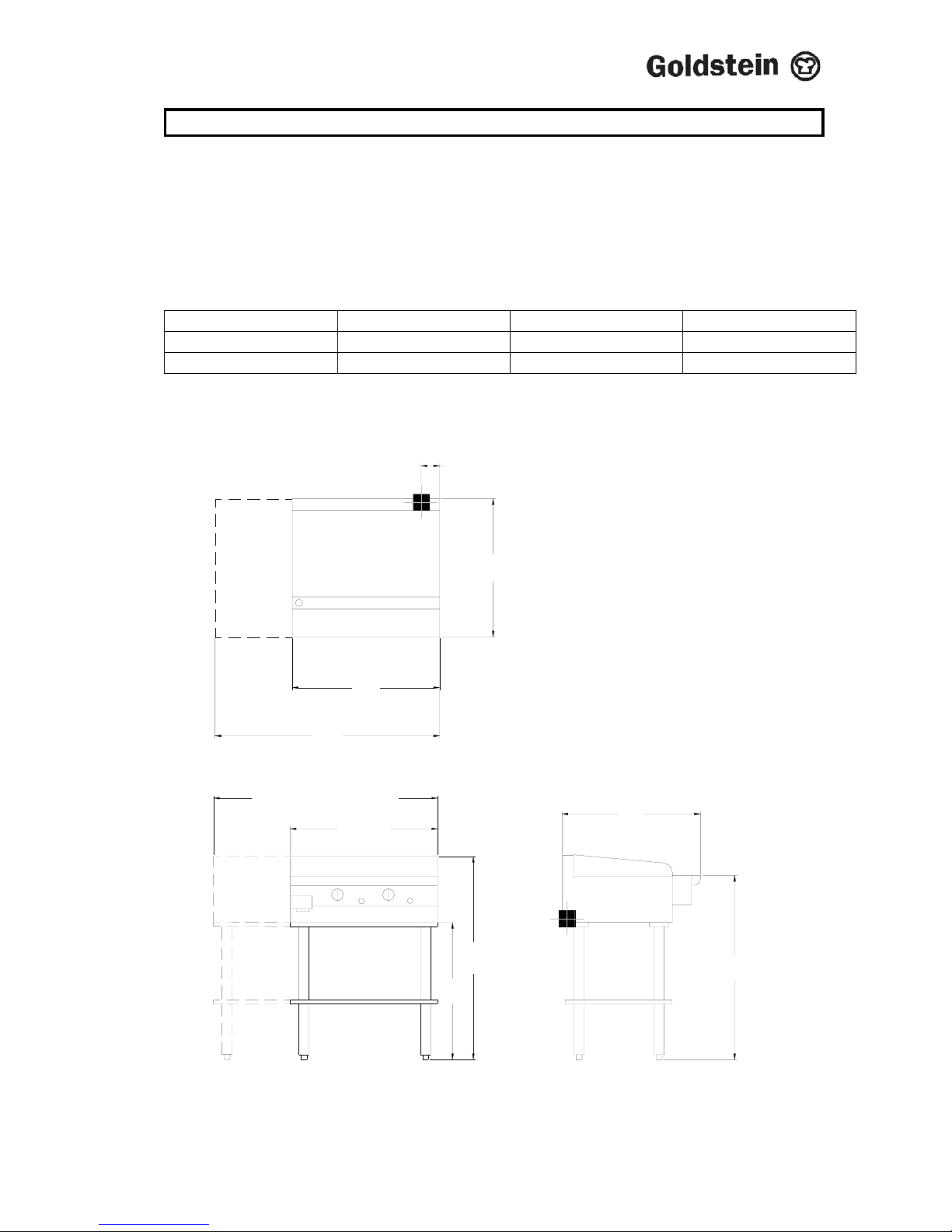
MODEL WIDTH (MM) DEPTH (MM) HEIGHT (MM)
GPG-30 745 690 445
GPG-45 1130 690 445
SIDE VIEW
GPG-45 or AGPG/S-45
690
FRONT VIEW
GPG-30
GPG MODELS
GPG-45 or AGPG/S-45
1120
GPG-30
740
690
55
1015
915
685
IM027B2/p11

8. CLEANING INSTRUCTIONS
CLEANING/MAINTENANCE OF GRIDDLE PLATE
Frequently during the cooking, clean griddle plate with scraper (this will prevent food
build up and will make the final daily cleaning of the griddle plate easier).
Use a mild cleaner, CAUSTIC cleaners ARE NOT TO BE USED, otherwise warranty
will be void.
Before daily cleaning of the griddle plate, cool the plate to no more than 60C. Cooling
can be accelerated using water applied with a brush or well wetted cloth whilst wearing
gloves. DO NOT pour quantities of water direct onto a hot griddle place, as scalding
may result.
Clean down plate at the end of each working day. Thoroughly wash all traces of
cleaner off griddle plate with lukewarm soapy water, then rinse again and again with
fresh water and wipe thoroughly.
NOTE Ensure to empty out the grease can regularly while cleaning griddle otherwise
grease can will overflow.
Let griddle plate run on high for a few minutes to completely dry the water from the
plate.
Using a basting brush, after plate is completely dry and cool, cover the plate with a thin
layer of cooking oil to maintain the shinny appearance of the plate.
When cleaning the stainless steel surface under NO circumstances should wool
brushes or scraping implements of common steel be used on the stainless steel
because ferrous particles can deposit on the stainless steel surface causing by their
oxidation, rust spots.
Scotchbrite can also be used but it is necessary to always rub the surfaces in the
direction of the stainless steel finish.
If the appliance is to remain inoperative for a certain period, cover the griddle plate with
a thin layer of cooking oil, note that it is advantageous to keep the room in which the
appliance is installed.
Note
IF CAUSTIC SODA BASED OVEN CLEANERS ARE USED WARRANTY IS
VOID.
IM027B2/p12

9. PROBLEM SOLVING
CAUSE AND REMEDY FOR DEFECTIVE OVEN COOKING
1. Too much bottom heat, which results in burning on the bottom of
products also scorching on the sides. Products will be too light on top,
uneven in colour on the top and probably raw in the centre.
(a) Cause: Remedy
Insufficient (BTU) MJ input. Check for line or fit blockage
and clear
2. Too much top heat, which results in Dark top of products and light
bottom, possibly not cooked in centre.
(a) Cause: Remedy
Excessive (BTU) MJ input. Check burner injector orifice for
correct size also check governor
pressure.
(b) Cause: Remedy
Under active flue or flue restriction. Check for obstruction in flue
way.
3. Uneven cooking characteristics from side to side.
(a) Cause: Remedy
If single burner construction, oven Locate burner on level flame.
burner out of alignment.
(b) Cause: Remedy
Appliance not level side to side. Level appliance with spirit level.
(c) Cause: Remedy
Burner baffle (if fitted) tilted causing Replace baffle.
Products of combustion to be
directed to one side.
4. Baking characteristics from front to back.
(a) Cause: Remedy
Over-active flue Check that baffles, if fitted are in
place.
(b) Cause: Remedy
Unit not level, front to back Using spirit from front to
IM027B2/p13

9. PROBLEM SOLVING Cont’d
5. Dried out Product
(a) Cause: Remedy
Too low a temperature. Adjust gas cock accordingly.
(b) Cause: Remedy
Too long a cooking time. Adjust cooking time and
temperature to suit product.
6. Wide Variation of results from grill to grill.
(a) Cause: Remedy
Fluctuating gas pressure. Fit or adjust governor.
7. Pilot outage
(a) Cause: Remedy
Fluctuating pressure. Fit or adjust governor.
(b) Cause: Remedy
Contamination of pilot orifice. Clean pilot orifice.
(c) Cause: Remedy
Extreme over-gassing of main Check burner jet orifice size or
Burner. Governor adjustment.
(d) Cause: Remedy
Defective thermocouple Replace.
(e) Cause: Remedy
Defective safety shut-off valve. Replace.
(f) Cause: Remedy
Poor connection between thermocouple Refer to servicing instructions
and lead and valve. clean.
(g) Cause: Remedy
Too high or too low input to pilot. Refer servicing instructions and
adjust.
NOTE: Milivoltage tests required on 7 (d) and 7 (a).
IM027B2/p14

9. PROBLEM SOLVING Cont’d
8. Burner goes out and flashes back
(a) Cause Remedy
Excessive aeration. Adjust.
9. Yellow Flame
(a) Cause Remedy
Too much gas to burner. Check gas pressure and burner
Jet orifice.
(b) Cause Remedy
Insufficient aeration. Adjust
10. Harsh noisy flame
(a) Cause Remedy
Excessive aeration Adjust.
IM027B2/p15

10. DRAWING
MODEL: GPG-30, GPG-45
IM027B2/p16
5
1
11
2
14
10
9
13
4
2
1
12
7
8
6
3

10. SPARE PARTS
MODEL: GPG-30, GPG-45
ITEM No. CODE DESCRIPTION
1. MKNPLM21 KNOB – GASCOCK GCKPF001/GCKGR001 (PF BOIL.)
2. ESP00003 SPARKER – PIEZO C/W SPRING, WASHER, NUT
3. GCKGR001 GASCOCK – RBA/GPG/PF WITH F/F DEVICE
4. GIJPG210 INJECTOR – 2.10mm N/G
4. GIJPG130 INJECTOR – 1.30mm L/P
5. GIJ00022 PILOT SPUD FOR L.P.G
5. GIJ00032 PILOT SPUD FOR N/G
6. GPIC0002 ELECTRODE – CERAMIC GPIB0002 (509F)
7. GPIB0002 BODY – PILOT, POLIDO. PF/PFC OVEN PFG CHD
8. GTC00320 THERMOCOUPLE – L=320mm
9. ESPL0402 LEAD – H.T 400mm FOR SPARKER (GRIDDLE)
10. GBNGPG00 BURNER – GPG30 / GPG45
11. PF-00P33 AIR INLET CONTROL
12. PFG00A02 GREASE ASSEMBLY
13. MLESSBF1 FEET – S/S BULLET D=41mm (1 5/8”)
14. GMA00002 MAGNETIC ARMATURE – (OPEN BURNER) N21S
IM027B2/p17

11. DRAWINGS
MODEL GPGDB/SA – 24, 36
2
8
9
1
4
7
2
1
1
1
1
1
6
5
6
2
9
1
1
9
5
1
1
3
1

IM027B1/p18
11. SPARE PARTS
MODEL: GPGDB/SA – 24,36 GPGDB/SA – 24, 36
ITEM No. CODE DESCRIPTION
1. GBNGPSAL BURNER – GPGD/SA (SINGLE) LH
2. GBNGPSAC BURNER – GPGD/SA (SINGLE) CENTER (25MJ)
3. GBNGPSAR BURNER – GPGD/SA (SINGLE) RH
4. PFG00A02 GREASE CAN ASSEMBLY
5. GIJGP070 INJECTOR – OUTER 0.70mm L/P
5. GIJGP110 INJECTOR – OUTER 1.10mm N/G
6. GIJGP100 INJECTOR – INNER 1.00mm L/P
6. GIJGP160 INJECTOR – INNER 1.60mm N/G
7. GGS24M01 TRAY – TOASTER GPGSA24
8. GGS24P08 DRIP TRAY
9. MKNPLM21 KNOB – GASCOCK GCKPF001/GCKGR001 (PF BOIL.)
10. GCKGR001 GASCOCK – RBA/GPG/PF WITH F/F DEVICE
11. MLESSBF1 FEET – S/S BULLET D=41mm (1 5/8”)
12. MLEPLBF1 FEET – PLASTIC BULLET 2D
13. ESP00003 SPARKER – PIEZO C/W SPRING, WASHER, NUT
14. ESPL0402 LEAD – H.T 400mm FOR SPARKER GRIDDLE
15. GTC00320 THERMOCOUPLE – L=320 (TOP BURNER)
16. GPI00003 PILOT – RBA/GPGDSA (3 WAY)
17. GPIC0003 ELECTRODE – CERAMIC GPI00003 PILOT
18. MLESSBFA STAINLESS STEEL LEG WITH ADJ. PLASTIC INSERT
19. GGS00A03 COPPER PIPE MANIFOLD TO INJECTOR – GPGDSA
20. GMA00002 MAGNETIC ARMATURE – (OPEN BURNER) N21S
21. GGS00M02 GAS BURNER 393D FRET
IM027B2/p19

12. WARRANTY
Installation must be carried out according to local regulations by qualified trade
persons.
Isolating switch(es), shut-off valves etc must be within easy reach of the machine for
future service and maintenance requirements.
If in doubt call GOLDSTEIN/ESWOOD or their representative for further information.
No responsibility will be accepted for defects or damages by improper installation, for
changes to the product not authorised by GOLDSTEIN/ESWOOD or for operation
outside the technical specifications.
GOLDSTEIN/ESWOOD warrants their products to be free from defects in material and
workmanship under “normal use and service”. This does not include normal wear and
tear of parts. GOLDSTEIN/ESWOOD will repair or replace any parts, which in
GOLDSTEIN/ESWOOD’s sole judgement are defective in material or workmanship, in
accordance with the warranty offered.
This undertaking covers the provision of labour and parts for 12 months from the date
of delivery to the purchaser. This undertaking applies only to state capitals. Remote
areas are not covered by this commitment and special enquiries should be made.
(Note
: Travel time not covered by warranty).
“To the maximum extent permitted by law, any liability on Goldstein/Eswood’s part or
on the part of its servants or agents for loss or damage of any kind whatsoever in
connection with the products, including liability for or in respect of any claim arising out
of contract, negligence or statute, shall not, in any event, exceed $100”
Labour under warranty is supplied free of charge during normal working hours, Monday
to Friday. Should warranty work be requested outside of our normal working hours a
labour charge will be applied equivalent to a normal hour rate, without out of hours
penalty rates. Refer to last page of this manual for your closest branch for warranty
repair services).
IM027B2/p20

13. J GOLDSTEIN & CO PTY LTD BRANCHES
For inquiries please call your nearest state branch:
Head Office
211-213 Woodpark Road
New South Wales 2564
Phone: 02 9604 7333
Fax: 02 9604 5420
Victoria
Queensland
Unit 13 Unit 3
260-264 Wickham Road 49 Logan Road
Moorabbin Woolloongabba
Victoria 3189 Queensland 4102
Phone: 03 9553 1488 Phone: 07 3891 1466
Fax: 03 9553 0785 Fax: 07 3393 1333
South Australia
Western Australia
Suite 26 10 Wittenberg Drive
283-287 Sir Donald Bradman Drive Canning Vale
South Australia 5032 Western Australia 6155
Phone: 08 8238 3423 Phone: 08 9456 0559
Fax: 08 8238 3400 Fax: 08 9456 0554
IM027B2/p21
 Loading...