

Page 1
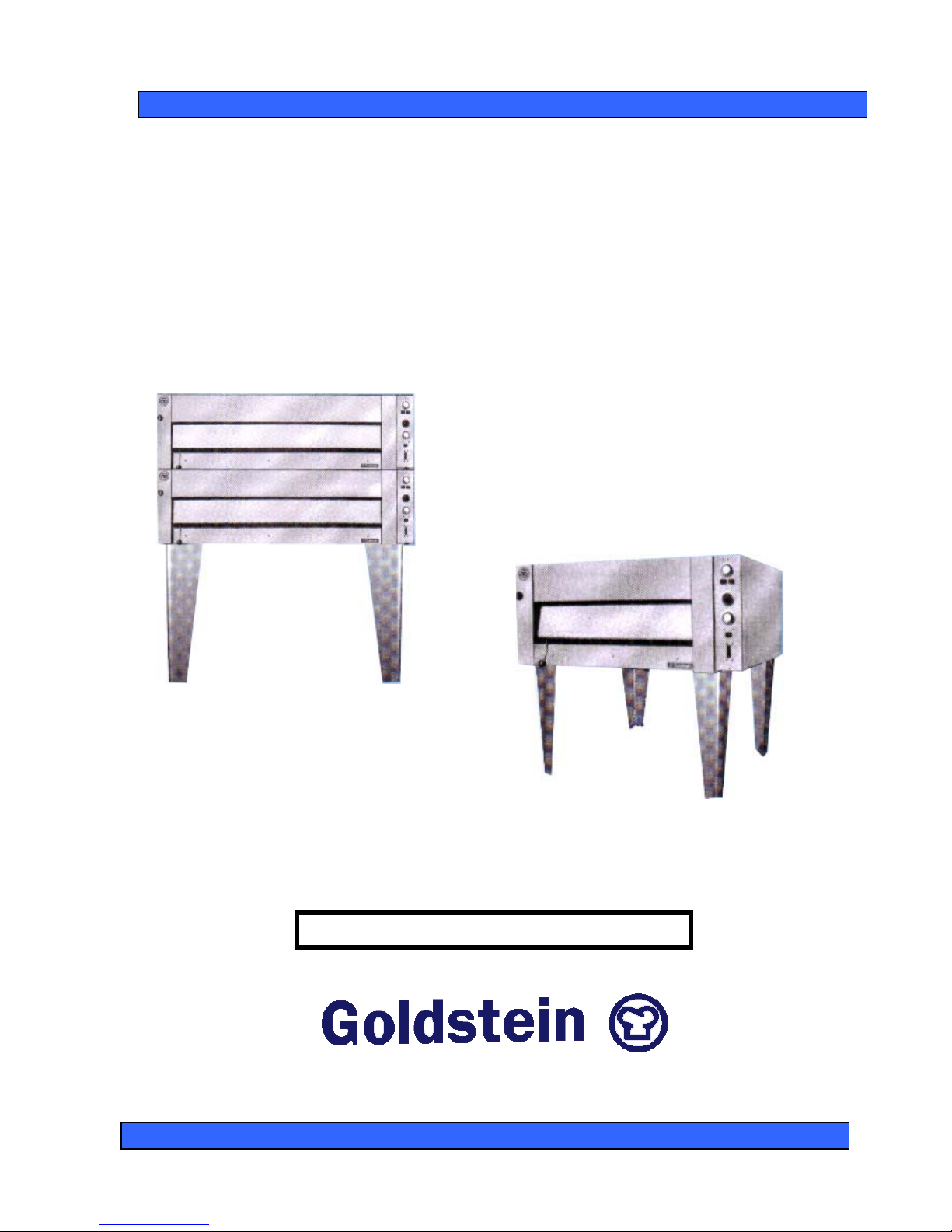
ELECTRIC BAKE AND PIZZA OVEN
PROUDLY AUSTRALIAN MADE
INSTALLATION PROCEDURE – USER MANUAL
SERVICE INSTRUCTION
MODELS E-201, E-541 AND MULTIPLES
E-542
E-201
ELECTRICAL APPROVAL CS 365
ESTABLISHED 1911
The Cooking Equipment Professionals
www.goldsteineswood.com.au
Page 2

TABLE OF CONTENTS
1. INTRODUCTION Page 3
2. COMMISSIONING Page 4
3. INSTALLATION Page 5
4. OPERATING INSTRUCTIONS Page 6
5. CLEANING & SERVICING Page 7
6. WIRING DIAGRAM E-201 Page 8
7. WIRING DIAGRAM E-541 Page 9
8. DRAWINGS Page 10
9. SPARE PARTS Page 11
10. WARRANTY Page 12
11. BRANCHES Page 13
IM010B1/p2
Page 3

1. INTRODUCTION
Congratulations for purchasing your Goldstein commercial cooking appliance.
J. Goldstein & Co. is a wholly owned Australian company and has been
operating since 1911, building high quality products. The information in this
manual will assist your installer and ensure correct location and connection.
Thoroughly read the user instructions and the user maintenance sections, as
understanding your products, its operation, and its cleaning and service
requirements will provide you with long and satisfactory service. Failure to do
so could shorten the life of the product and decrease its efficiency. Please
ensure only authorised service technicians are called to any difficulties that
may arise.
INTRODUCTION
GOLDSTEIN ELECTRIC BAKE & PIZZA OVEN
MODELS E-201, E-541, AND MULTIPLES
GOLDSTEIN ELECTRIC BAKE AND PIZZA OVENS are designed to give long and
satisfactory service and incorporate the best possible materials and workmanship.
Proper installation, adjustment and preventative maintenance are vitally important if
efficiency and appearance are to be maintained.
Read these instructions carefully as they contain important safety information
regarding the installation, use and maintenance of the appliance.
RECEIVING INSPECTION
•
Check crates for handling damage. After carefully uncrating, check for
“concealed” damage. Report any damage immediately to carrier and to dealer.
•
Remove check all loose items from unit and check contents as found on back of
warranty cards.
“THE EQUIPMENT MUST BE INSTALLED BY A
LICENSED ELECTRICIAN”
IM010B1/p3
Page 4

2. COMMISSIONING
COMMISSIONING APPLIANCE – DETAILS, TESTING, CHECKING PRESSURE
ETC.
COMMISSIONING CHECK LIST
1. CHECK FOR DAMAGE AND MISSING PARTS ON BACK OF WARRANTY
CARD.
2. REMOVE ALL PLASTIC COATING FROM S/STEEL PANELS.
3. MAKE SURE ALL PARTS ARE IN THEIR CORRECT POSITION E.G.
TRAYS CONTROL KNOBS.
4. MAKE SURE ALL GAS CONNECTIONS ARE CORRECT AND TIGHT.
5. LEVEL OFF UNIT LEFT TO RIGHT AND FRONT TO BACK.
6. TURN ON ELECTRICITY.
7. TURN ON ONE AT A TIME TO MAKE SURE ALL IS WORKING E.G.
BURNER, RADIANT, GRIDDLE AND OVEN.
8. SHOW CUSTOMER
A) HOW TO WORK EQUIPMENT
B) HOW TO CLEAN
C) HOW TO PULL IT APART E.G. TRAYS.
D) ALSO WHAT NOT TO DO, E.G. GREASE AND OIL IN CONTROLS.
9. CHECK TO MAKE SURE MANUALS AND WARRANTY CARD IS THERE.
ALSO GO THROUGH MANUAL WITH CUSTOMER
NOTE:
WASH HOSES SHOULD NEVER BE USED ON THE APPLIANCE.
USE OF HOSES WILL VOID WARRANTY.
IM010B1/p4
Page 5

3. INSTALLATION INSTRUCTIONS
INSTALLATION OF THE OVEN
A. Before Assembly and Connection
1. Check for damage,
2. Check crates for handling damage. After carefully uncrating, check for
“concealed” damage. Report any damage immediately to carrier and to
dealer.
3. Check electrical supply.
B To assemble Legs
1. Tilt oven over to left hand side and attach two legs on right hand side with four
(4) bolts.
2. Lift up left hand side of oven and attach legs there the same way.
PLEASE NOTE: Level the oven by adjusting the socket feet.
C Electrical Connection
(FOR AUTHORISED TECHNICIANS ONLY)
1. Make sure that it corresponds with the specified rating plate.
2. Connect supply conduit to control panel.
3. Connect supply lines to the terminal block in the oven.
4. When the circuit breaker is on all power is fed to all components.
5. Ego simmerstat overrides the thermostat so in heating up the simmerstat
should be on full for the thermostat to operate.
NOTICE
PLEASE RETURN YOUR WARRANTY CARD
FAILURE TO DO SO WILL VOID
WARRANTY ON THE EQUIPMENT
IM010B1/p5
Page 6

4. OPERATING INSTRUCTIONS
OVEN OPERATION .
1. Always load the deck of the oven with pans spaced away from each side and
the back of the oven to allow even distribution of heat.
2. The required temperature for the oven should be set on the thermostat and
the simmerstat should be set at full for the heating of the oven.
When the oven comes up to temperature the simmerstat can be set at a lower
setting between 2 and 3 to allow the elements to oscillate in and out and allow
a gradual increase and decrease in temperature rather than letting the
elements stay in continuous heat until the temperature in the oven is
maintained. The setting of the simmerstat is based on experience and
personal preference of the operator and need not be used for all cooking
operations.
3. Top elements are often not required in most baking operations and are
generally used for browning and in cooking pizzas.
4. A damper is located in the control panel and allows the moisture to escape
from the oven and can be closed for sponge and light cake mixture.
IM010B1/p6
Page 7

5. CLEANING & SERVICE INSTRUCTIONS
CLEANING
This is a most essential part of general maintenance and to ensure satisfactory
operation of any appliance must be carried out at very regular intervals. The use of
water on or near any electrical element or connection point must be avoided. At the
most a damp cloth may be used after excess grease has been removed with a
degreaser, NOT CAUSTIC SODA.
Daily cleaning of your appliance will be amply repaid in longer life and more efficient
operation.
To maintain the lustrous finish of the stainless steel, regular cleaning with soap and
water is usually all you need. Just wipe surface with damp cloth or soft leather, using
scrubbing brush. If necessary, for corners or crevices. Dry the steel and polish with
a leather or soft dry cloth.
NEVER USE ORDINARY STEEL WOOL, any metallic scouring
materials or harsh abrasives.
PLEASE NOTE: Always clean oven when it is COLD.
SERVICE INSTRUCTIONS
Disconnect from mains supply by removing fuses or turning off circuit breaker. The
controls and wiring are readily accessible after the lower stainless steel fascia plate is
removed. Care must be taken with this panel as all the wiring and thermostats are
attached.
IM010B1/p7
Page 8
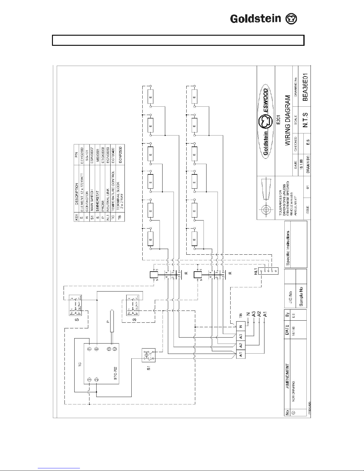
6 WIRING DIAGRAM
MODEL E-201 2 BANKS OR 4 ELEMENTS
IM010B1/p8
Page 9
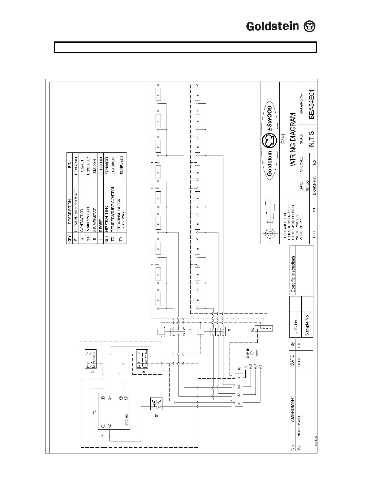
7 WIRING DIAGRAM
MODEL E-541, 2 BANKS OF 6 ELEMENTS
IM010B1/p9
Page 10
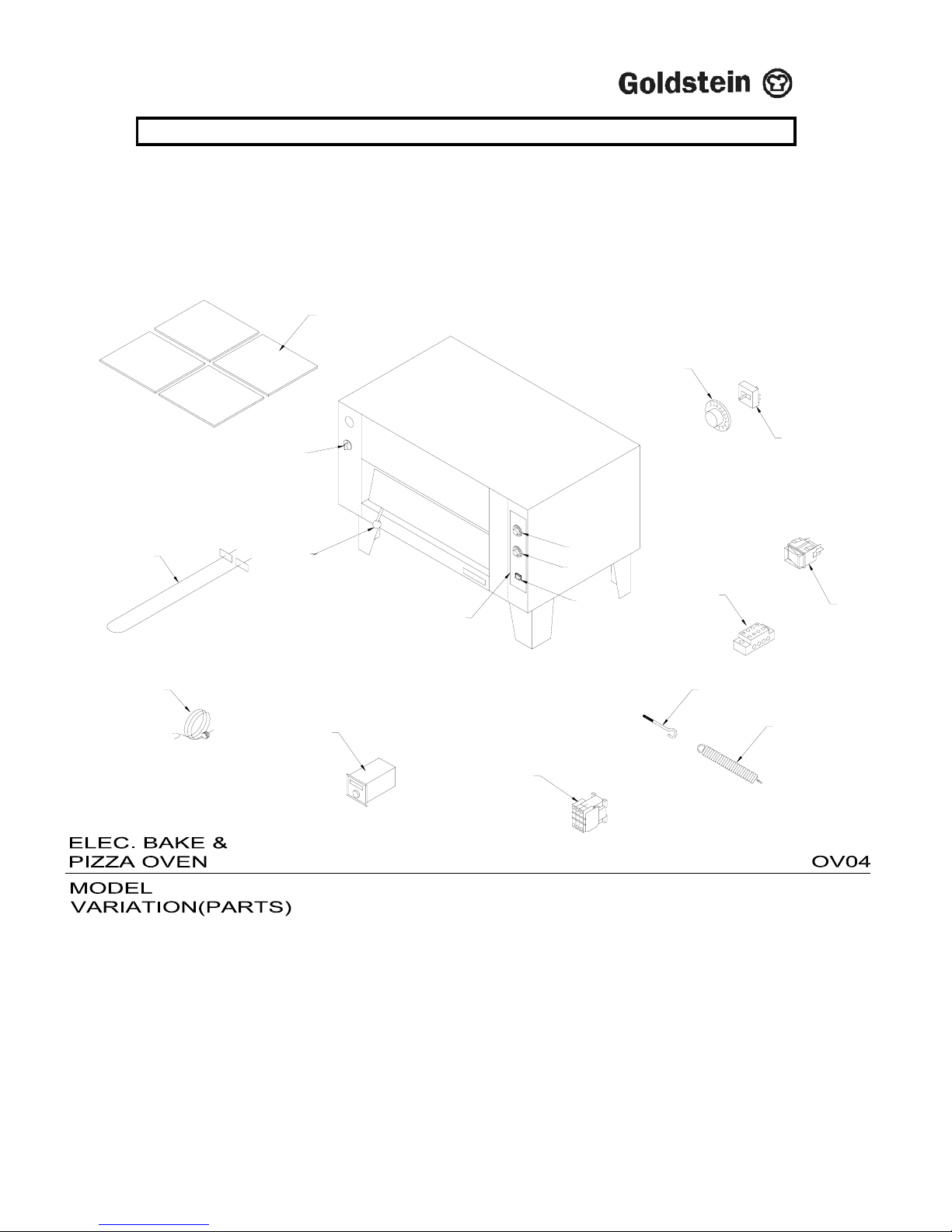
8. DRAWING
MODEL: E201, E202, E541, E542
IM010B1/p10
O
F
F
N
O
12
11
13
9
5
1
1
3
14
10
6
8
7
3
4
2
1
Page 11

9. SPARE PARTS
MODEL: E201, E202, E541, E542
ITEM No. CODE DESCRIPTION
1. MKNPLTS4 KNOB – ENERGY REGULATOR
2. MSI00001 SIMMERSTAT – RADIANT (NEW TYPE)
3. ESW00007 SWITCH – MAIN. WITH SILICONE BOOT
4. MINKB013 INSULATION – KILN BATTS BEA/BEB
5. MKN00004 BLACK KNOB
6. ETCK0000 OLD TYPE “K” THERMOCOUPLE BRAIDED
7. ECT45AK2 CONTACTOR – 45A (MODELS: E541, E542)
7. ECT25AK2 CONTACTOR – 25A (MODELS: E201, E202)
8. ETC00400 CONTROL – TEMPERATURE (400°C) FOR PIZZA
9. MKNSSCK1 KNOB – CHROME METAL CW/CHD GASCOCK GCKC
10. EEVG0900 ELEMENT – 0.77/0.7KW
11. SA-00M11 DOOR SPRING
12. PF-00M07 EYE BOLT
13. ECNP4S30 4 WAY PORCELAIN CONNECTOR
14. GLA00008 LABEL
IM010B1/p11
Page 12

10. WARRANTY
Installation must be carried out according to local regulations by qualified trade
persons.
Isolating switch(es), shut-off valves etc must be within easy reach of the machine for
future service and maintenance requirements.
If in doubt call GOLDSTEIN/ESWOOD or their representative for further information.
No responsibility will be accepted for defects or damages by improper installation, for
changes to the product not authorised by GOLDSTEIN/ESWOOD or for operation
outside the technical specifications.
GOLDSTEIN/ESWOOD warrants their products to be free from defects in material
and workmanship under “normal use and service”. This does not include normal
wear and tear of parts. GOLDSTEIN/ESWOOD will repair or replace any parts,
which in GOLDSTEIN/ESWOOD’s sole judgement are defective in material or
workmanship, in accordance with the warranty offered.
This undertaking covers the provision of labour and parts for 12 months from the date
of delivery to the purchaser. This undertaking applies only to state capitals. Remote
areas are not covered by this commitment and special enquiries should be made.
(Note
: Travel time not covered by warranty).
“To the maximum extent permitted by law, any liability on Goldstein/Eswood’s part or
on the part of its servants or agents for loss or damage of any kind whatsoever in
connection with the products, including liability for or in respect of any claim arising
out of contract, negligence or statute, shall not, in any event, exceed $100”
Labour under warranty is supplied free of charge during normal working hours,
Monday to Friday. Should warranty work be requested outside of our normal working
hours a labour charge will be applied equivalent to a normal hourly rate, without out
of hours penalty rates. (Refer to last page of this manual for your closest branch for
warranty repair services).
IM010B1/p12
Page 13

11. J GOLDSTEIN & CO PTY LTD BRANCHES
For inquiries please call your nearest state branch:
Head Office
211-213 Woodpark Road
New South Wales 2564
Phone: 02 9604 7333
Fax: 02 9604 5420
Victoria
Queensland
Unit 13 Unit 3
260-264 Wickham Road 49 Logan Road
Moorabbin Woolloongabba
Victoria 3189 Queensland 4102
Phone: 03 9553 1488 Phone: 07 3891 1466
Fax: 03 9553 0785 Fax: 07 3393 1333
South Australia
Western Australia
Suite 26 10 Wittenberg Drive
283-287 Sir Donald Bradman Drive Canning Vale
South Australia 5032 Western Australia 6155
Phone: 08 8238 3423 Phone: 08 9456 0559
Fax: 08 8238 3400 Fax: 08 9456 0554
IM010B1/p13
 Loading...