

Page 1
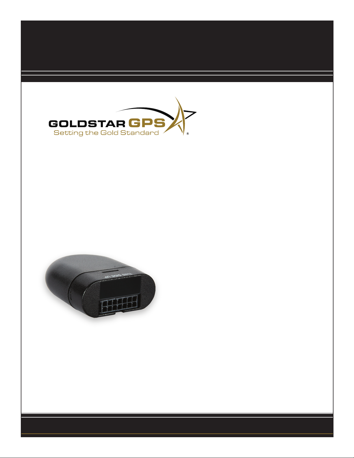
The ROCKET Install Guide
TM
Table of Contents
Standard Installation
Standard Starter Disable Installation
Starter Disable with ECM Installation
Installation Do’s and Don’ts
.....................................................................................................................2
........................................................................................................4
the
.......................................................................................3
......................................................................................3
Gold
Standard
in GPS tracking
Toll Free Support
877.563.0012
GLD-C-S-0710-ROCKET
Page 2
The ROCKET Standard Installation
TM
Getting Started
The ROCKET model is a completely self-contained device, requiring only a constant power and ground
TM
to operate. Within the case are two antennas for both GPS data and GSM/GPRS communication. This
device is easily installed in a concealed location under the dash.
Installation
For customers installing the starter disable feature, please see page 3 for more instructions.
The ROCKET requires constant power to operate properly. The red wire will need to be connected to a
TM
constant +12V source. This can easily be located under the dash; fuse panels are good places to start, as
well as the thicker gauge wires. The black wire will need to be connected to a solid ground. Always use a
bolt directly connected to the chassis to ensure a good ground. Using smaller bolts connected to secondary frames will result in occasional power loss. With the warning buzzer system, the white wire will need
to be connected to the ignition wire.
REMEMBER TO ALWAYS TEST THE RED WIRE IN ALL KEY POSITIONS TO ENSURE THE
VOLTAGE NEVER DROPS DURING NORMAL OPERATION.
Mounting
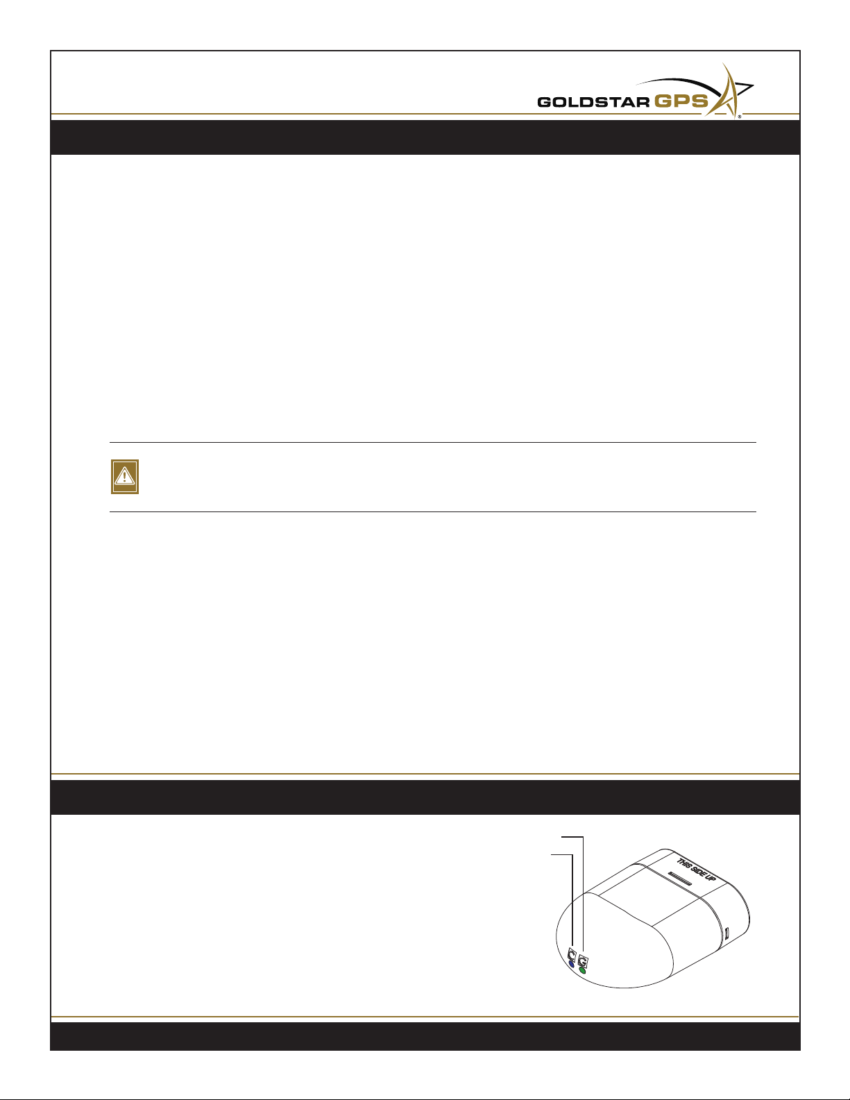
When mounting the THIS SIDE UP imprint needs to be face up towards the sky and there
The ROCKET
TM
should be no metal above the device. The device’s internal antennas will be able to get signal through
plastic, glass, etc., but metal objects can interfere.
Powering Up
Once the wires are attached and the device is mounted, plug the harness into the device to power it up.
Once powered up, the LED indicators will show a fast ashing green light, indicating good GPS signal,
and a slow ashing blue for good cellular coverage. If the green light remains solid, you are not getting a
GPS signal. If you are unable to get a GPS and cellular signal after waiting 5 minutes, reposition and try
again. It may take up to 15 minutes to get an initial GPS lock.
LED Troubleshooting
GPS
Green
• Solid - No GPS
• Flashing - Good GPS
Blue
• 1 Flash On, 3 Count Off - Good Cellular Coverage
• 1 Flash On, 1 Count Off - No Cellular Coverage
Cellular
Support: 877.563.0012
2
Page 3
Standard Starter Disable Installation
Wiring
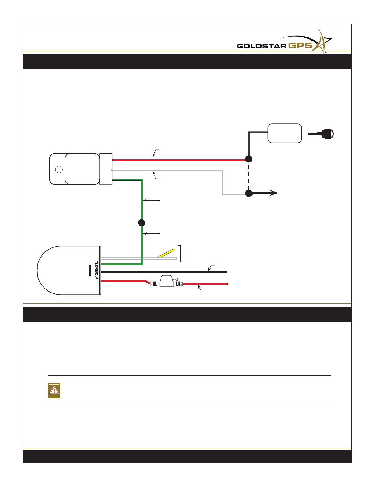
The starter disable relay is inserted into the +12V starter wire. Cut this wire and connect the red wire from
the relay to the +12V supply into the relay. The white wire from the relay connects to the cut wire going to
starter. The green wire from the relay will connect to the green wire from the device harness.
IGNITION
SWITCH
RED
SOCKET
RELAY
WHITE
GREEN
GREEN
CUT
TO STARTER
The ROCKET
YELLOW - Not Used
WHITE -
TM
FUSE
Key ignition sense (warning buzzer)
BLACK (ground)
RED (+12V)
Starter Disable with ECM Installation
Background
The starter disable with ECM installation needs to be performed whenever any sort of control or security
module is installed between the key (ignition) and the starter. In these cases, the standard starter disable
installation does not apply. The starter wire goes into an onboard computer, generally carrying a low
voltage into it instead of the standard 12 volts.
YOU WILL NEED TO HAVE A VOLTAGE METER, NOT A TEST LIGHT. IF YOU TAP A WIRE WITH
Ê
A LOW VOLTAGE (3-5 V0LTS) YOU MAY LOCK DOWN THE VEHICLE!
Follow the low voltage wire from the ignition key to the ECM. Use your voltage meter to ensure that it is a
12 volt supply coming out. Once you’ve located the proper 12 volt wire after the ECM, proceed with the
regular starter interrupt instructions (given above) using this wire.
Support: 877.563.0012
3
Page 4

Installation Do’s and Don’ts
DO
• Ground directly to the frame
• Make solid splices and insulate them well
• Secure the device and all wiring
• Ensure the proper light sequence before closing up the dash
• Use a constant 12v power supply
DON’T
• Use small screws for grounding that are not attached to the frame
• Use a pulsating 12v power supply
• Splice wires together loosely without insulating properly
• Let the device and wiring hang loosely
Support: 877.563.0012
4
 Loading...