

Page 1
MICROW AVE OVEN
SER VICE MANUAL
MODEL: MA-1303BRV
CAUTION
BEFORE SERVICING THE UNIT, READ THE
SAFETY PRECAUTIONS IN THIS MANUAL.
http://www.LGEservice.com
e-mail:techsupport@LGEservice.com
Page 2

This device is to be serviced only by properly qualified service personnel.
Consult the service manual for proper service procedures to assure continued safety operation and for precautions to be
taken to avoid possible exposure to excessive microwave energy.
PRECAUTIONS TO BE OBSERVED BEFORE AND
DURING SERVICING TO AVOID POSSIBLE
EXPOSURE TO EXCESSIVE MICROWAVE ENERGY
A) Do not operate or allow the oven to be operated with the door open.
B) Make the following safety checks on all ovens to be serviced before activating the magnetron or other
microwave source, and make repairs as necessary; (1) interlock operation, (2) proper door closing, (3)
seal and sealing surfaces (arcing, wear, and other damage), (4) damage to or loosening of hinges and
latches, (5) evidence of dropping or abuse.
C) Before turning on microwave power for any service test or inspection within the microwave generating
compartments, check the magnetron, wave guide or transmission line, and cavity for proper alignment,
integrity, and connections.
D) Any defective or misadjusted components in the interlock, monitor, door seal, and microwave generation
and transmission systems shall be repaired, replaced, or adjusted by procedures described in this manual
before the oven is released to the owner.
E) A microwave leakage check to verify compliance with the Federal Performance Standard and CSA should
be performed on each oven prior to release to the owner.
SAFETY PRECAUTIONS
Page 3
1-1
It is not recommended for commercial purposes.
ITEM
MODEL
Power Requirement
Power Output
Microwave Frequency
Magnetron
Timer
Outside Dimensions
Cavity Dimensions
Net Weight
Shipping weight
Control Complement
Accessories
DESCRIPTION
MA-1303BRV
120 Volts AC 60 Hz
1,300 Watts (12.0A)
Single phase, 3 wire grounded
900 Watts full microwave power (IEC705)
2,450 MHz
2M214
0 ~ 99 min. 99 sec.
217/8
˝ (W) x 125/8˝ (H) x 171/4˝ (D)
14
3/4˝ (W) x 91/4˝ (H) x 16˝ (D)
37 lbs (approx.)
40 lbs (approx.)
Touch Control System
Clock : 1:00 - 12:59
Microwave Power for Variable Cooking
Power level
HIGH
-------------------------------
Full power throughout the cooking time
9 (Saute)
------
approx. 90% of Full power, 8 (Reheat)
--------
approx. 80%
7 (Med.-High)
--------------
approx. 70%, 6 (Medium)
--------
approx. 60%
5 (Med.-Low)
---------------
approx. 50%, 4 (Defrost)
---------
approx. 40%
3 (Low)
--------------------
approx. 30%, 2 (Simmer)
---------
approx. 20%
1 (Warm)
------------------
approx. 10%
Owner's manual
Glass turntable
Rotating ring
SPECIFICATIONS
Page 4

FEATURES
CONTROL PANEL
1. DISPLAY WINDOW
2. ONE TOUCH COOK: This menu has been pre
programmed to cook food automatically by one touch.
3. MORE / LESS: All of the one touch cook and TIMED
COOK can be adjusted to cook food for a longer or shorter
time.
MORE Pressing MORE will add 10 seconds to the
cooking time.
LESS Pressing LESS will subtract 10 seconds of
cooking time.
4. AUTO DEFROST: This feature provides you with the best
defrosting method for frozen foods.
5. NUMBER: These used to set for time of day, cooking time,
power level, or defrost weight.
6. STOP/CLEAR: It used to stop oven and clear all entries
except time of day.
7. CUSTOM COOK: This feature allows you to set and
execute a frequently used single stage program.
8. CLOCK: It is used to set the time of day.
9. Kg/Lbs
10. POWER: You can select the desired power level for
cooking.
11. TIME: You can set the desired cook time.
12. EZ ON: You can extend cooking time in multiples of 30
seconds by repeatedly touching this pad during cooking.
13. START: This feature allows oven to begin functioning.
4-1
OPERATING INSTRUCTIONS
Oven Front Plate
Window Door Screen
Door Seal
Control Panel
Door Open Button
Safety Door Lock System
Turntable
Rotating Ring
Display Window
1
4
7
5
6
83
2
9
11
10
12
13
Page 5
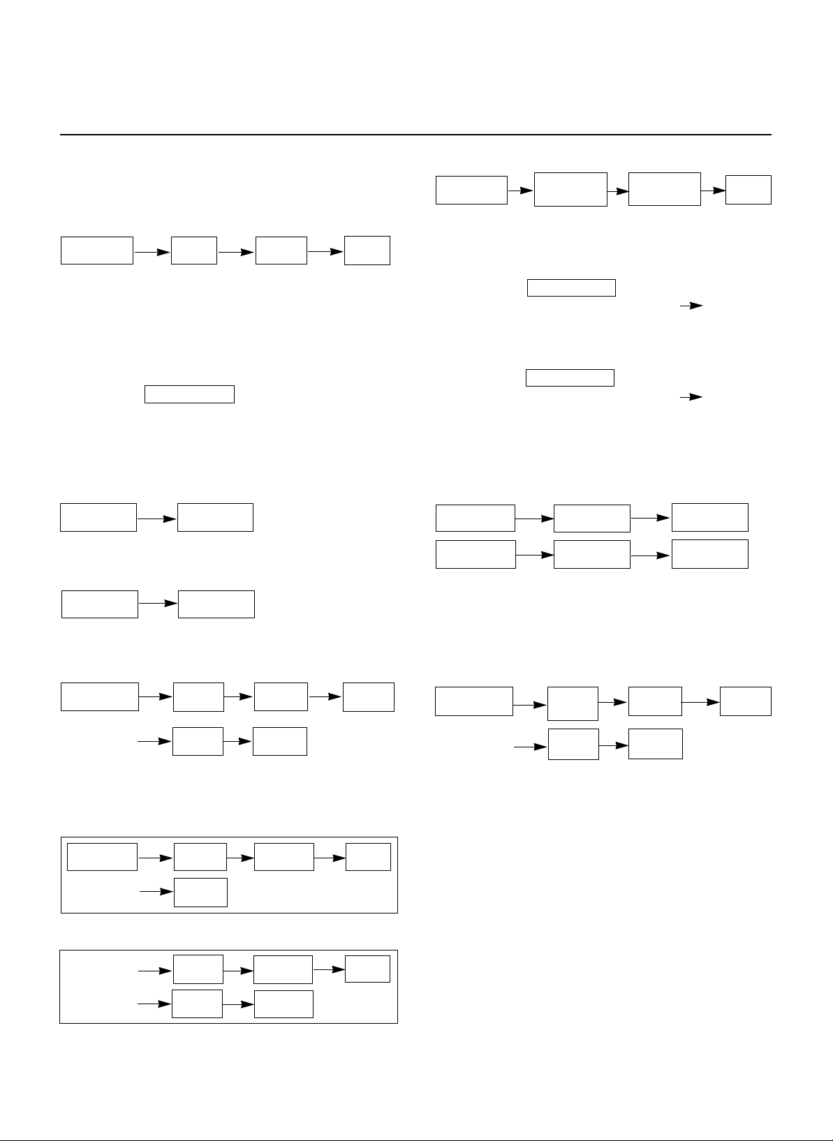
OPERATING SEQUENCE
The following is a description of component functions
during oven operation.
1. SETTING THE CLOCK
ex.) To set 4:30, touch number key [4],[3], and [0].
NOTE: 1) This is a 12 hour clock.
2) Clock will operate as long as power is
applied to the oven.
2. CANCEL FUNCTION
Touch the pad whenever you need to
cancel an entry or a function currently in use.
The display will either return to the last item entered
or to the clock.
3. EZ ON
4. ONE TOUCH COOKING
NOTE: Heat only 1 package at a time
5. TIME COOKING
6. MULTI-STAGE COOKING
7. AUTO WEIGHT DEFROST COOKING
8. CHILD LOCK
This oven has a CHILD LOCK feature
TO SET CHILD LOCK
• Touch the pad
• Touch and hold STOP/CLEAR pad LOCK
appear on the display.
TO CANCEL CHILD LOCK
• Touch the pad
• Touch and hold STOP/CLEAR pad LOCK
disappears.
9. MORE / LESS
The cook time is adjustable by MORE pad or LESS
pad
10. CUSTOM COOK
You can program the cook time and power level by
using CUSTOM COOK pad.
ex) To set cook time 10 mine 30seconds, touch
number key [1],[0],[3], and [0]
4-2
STOP/CLEAR CLOCK
NUMBER
STOP/CLEAR POPCORN
STOP/CLEAR EZ on
STOP/CLEAR
COOKING
MORE
STOP/CLEAR COOKING
LESS
STOP/CLEAR
1ST STAGE
CLOCK
STOP/CLEAR
AUTO WEIGHT
DEFROST
NUMBER OF
WEIGHT
START
STOP/CLEAR
CUSTOM
COOK
NUMBER POWER
NUMBER
START
STOP/CLEAR
TIME
NUMBER
POWER
NUMBER START
STOP/CLEAR
TIME
NUMBER POWER
NUMBER
2ND STAGE
TIME
NUMBER
POWER
NUMBER
START
STOP/CLEAR
STOP/CLEAR
Page 6
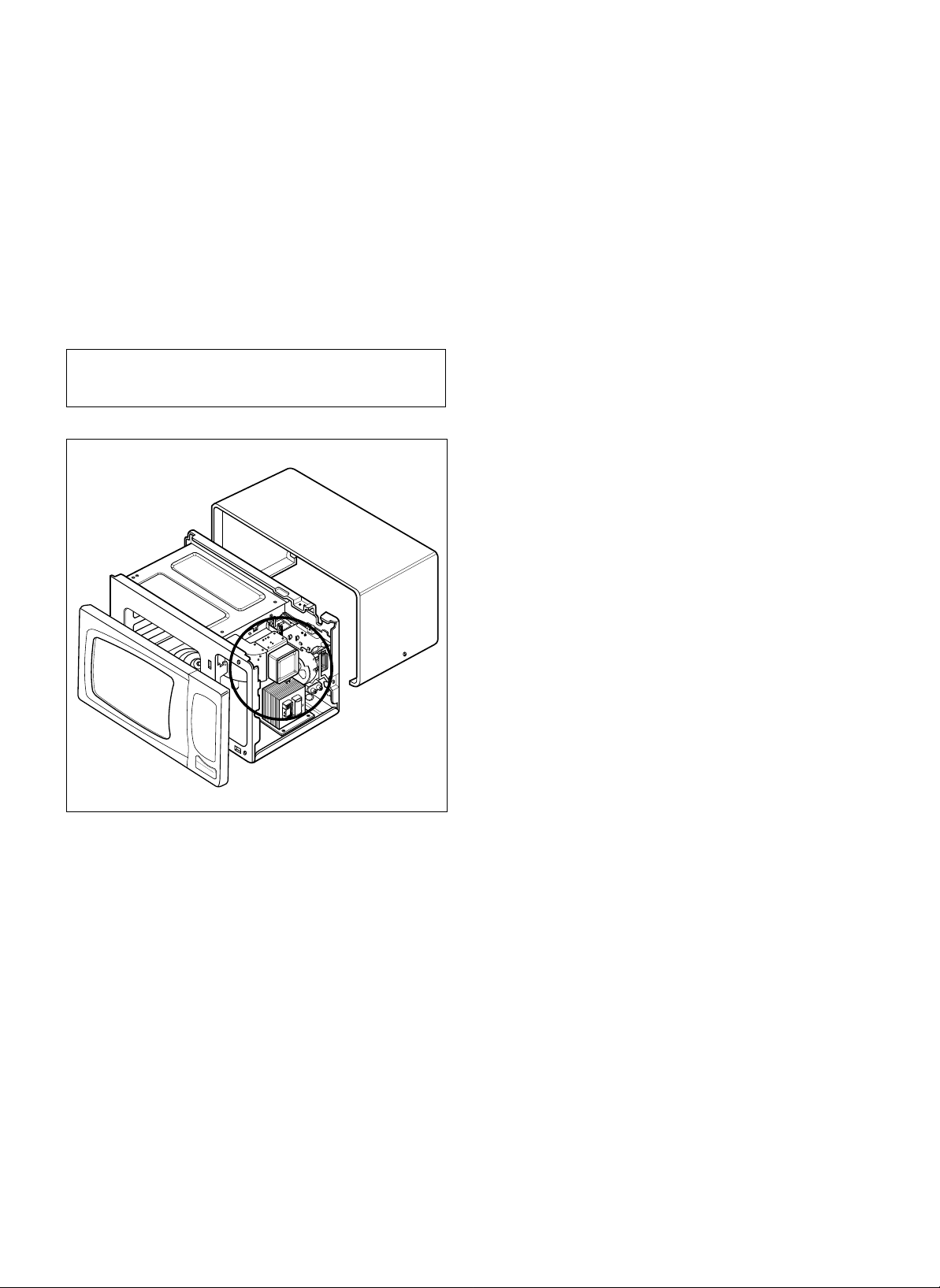
MEASUREMENT WITH OUTER CASE
REMOVED
• When you replace the magnetron, measure for
microwave energy leakage before the outer case is
installed and after all necessary components are
replaced or adjusted.
Special care should be taken in measuring the
following parts. (Circled area of Fig. below)
- Around the magnetron
- The waveguide
MEASUREMENT WITH A FULLY
ASSEMBLED OVEN
• After all components, including the outer case, are fully
assembled, measure for microwave energy leakage
around the door viewing window, the exhaust opening,
and air inlet openings.
• Microwave energy leakage must not exceed the values
prescribed below.
NOTE: Leakage with the outer case removed less than
5 mW/cm.sq. Leakage for a fully assembled
oven (Before the latch switch (primary) is
interrupted) with the door in a slightly opened
position-less than 2 mW/cm.sq.
NOTES WHEN MEASURING
• Do not exceed meter full scale deflection.
• The test probe must be removed no faster than
1 inch/sec (2.5 cm/sec) along the shaded area,
otherwise a false reading may result.
• The test probe must be held with the grip portion of the
handle.
A false reading may result if the operator's hand is
between the handle and the probe.
• When testing near a corner of the door, keep the probe
perpendicular to the surface making sure the probe
horizontally along the oven surface; this may possibly
cause probe damage.
RECORD KEEPING AND NOTIFICATION
AFTER MEASUREMENT
• After adjustment and repair of any microwave energy
interruption or microwave energy blocking device,
record the measured values for future reference. Also
enter the information on the service invoice.
• The microwave energy leakage should not be more
than 4 mW/cm.sq. after determining that all parts are in
good condition, functioning properly and genuine
replacement parts which are listed in this manual have
been used.
• At least once a year, have the electromagnetic energy
leakage monitor checked for calibration by its
manufacturer.
5-2
WARNING : AVOID CONTACTING ANY
HIGH VOLTAGE PARTS
Page 7

• Microwave power output measurement is made with
the microwave oven supplied at its rated voltage and
operated at its maximum microwave power setting with
a load of (1000±5) g of potable water.
• The water is contained in a cylindrical borosilicate glass
vessel having a maximum material thickness of 3 mm
and an outside diameter of approximately 190mm.
• The oven and the empty vessel are at ambient
temperature prior to the start of the test.
• The initial temperature (T1) of the water is (10±2)°C It
is measured immediately before the water is added to
the vessel. After addition of the water to the vessel,
the load is immediately placed on the center of the
turntable which is in the lowest position and the
microwave power switched on.
• The time T for the temperature of the water to rise by a
value ∆ T of (10±2)°K is measured, where T is the time
in seconds and ∆T is the temperature rise. The initial
and final water temperatures are selected so that the
maximum difference between the final water
temperature and the ambient temperature is 5°K.
• The microwave power output P in watts is calculated
from the following formula :
4187 x (∆T)
T
is measured while the microwave generator is
operating at full power. Magnetron filament heat-up
time is not included. (about 3 sec)
• The water is stirred to equalize temperature throughout
the vessel, prior to measuring the final water
temperature.
• Stirring devices and measuring instruments are
selected in order to minimize addition or removal of
heat.
A. OUTER CASE REMOVAL
1) Disconnect the power supply cord from the outlet.
2) Remove the screws from the rear of the case.
The outer case must be moved backward to be lifted
off.
B. POWER SUPPLY CORD
1) Remove the outer case.
2) Disconnect two terminals, and remove one screw of
the ground terminal.
C. CONTROL PANEL ASSEMBLY
1) Open the door.
2) Disconnect the leadwire from RELAY(RY2) of the
PCB SUB ASS’Y.
3) Lift up and pull out control panel assembly carefully
from the cavity.
4) Disconnect the leadwire from connector(CN1) of the
PCB SUB ASS’Y.
CAUTION: DISCHARGE THE HIGH VOLTAGE
CAPACITOR BEFORE SERVICING
(refer to page 2-1)
5-3
WATER LOAD
TURNTABLE
MEASUREMENT OF MICROWAVE POWER OUTPUT
P =
Remove the screw
Lift up and pull out control panel
DISASSEMBLY AND ADJUSTMENT
ground screw
Page 8

D. PCB ASSEMBLY REMOVAL
1) Remove the control panel assembly from the
cavity. (Refer to control panel assembly removal
on previous page.)
2) Remove screws which hold the PCB SUB ASS’Y to
the control panel.
3) Disconnect the flat cable from the PCB SUB
ASS’Y and take off the PCB SUB ASS’Y
E. DOOR MAIN ASSEMBLY REMOVAL
1) Open the door.
2) Remove the choke cover cap very carefully with a
flat-blade screwdriver.
CAUTION : Be careful not to damage door seal plate
with the screwdriver.
3) Lift up and push the door.
NOTE:
1. After replacing the door, be sure to check that the
primary switch, monitor switch, and secondary switch
operate normally.
2. After replacing the door, check for microwave energy
leakage with a survey meter. Microwave energy must
be below the limit of 4 mW/cm. (with a 275 ml water
load)
3. When mounting the door assembly to the oven
assembly, be sure to adjust the door assembly parallel
to the chassis. Also adjust so the door has no play
between the inner door surface and oven frame
assembly. If the door assembly is not mounted
properly, microwaves may leak from the clearance
between the door and the oven.
5-4
Remove choke cover cap
Remove door
Spacer
Control Panel
Key Membrane
Button Spring
Door Open Button
PCB Sub Asm
Release
Lever
Page 9

F. AIR DUCT ASSEMBLY REMOVAL
1) Disconnect the leadwire from the lamp.
2) Remove the mounting screw to the magnetron.
G. MAGNETRON REMOVAL
1) Disconnect the leadwire from the magnetron.
2) Carefully remove the mountinth eg screws holding
the magnetron and the waveguide.
3) Remove the magnetron ASS’Y until the tube is
clear from the waveguide.
NOTE:
1. When removing the magnetron, make sure its
dome does not hit any adjacent parts, or it may be
damaged.
2. When replacing the magnetron, be sure to install
the magnetron gasket in the correct position and
be sure that the gasket is in good condition.
3. After replacing the magnetron, check for microwave
leakage with a survey meter around the
magnetron. Microwave energy must be below the
limit of 5 mW/cm2. (With a 275 ml. water load).
Make sure that gasket is rigidly attached to the
magnetron. To prevent microwave leakage,
tighten the mounting screws properly, making sure
there is no gap between the waveguide and the
magnetron.
H. REMOVING THE TURNTABLE MOTOR
1) Remove the turntable.
2) Remove the turntable shaft VERY CAREFULLY.
3) Lay the unit down on its back.
4) Remove the turntable motor cover.
The turntable base cover is easily removed by
pinching the six parts with a wire cutting.
5) Disconnect the leadwire from the turntable motor
terminals.
6) Remove the screw securing the turntable motor to
the oven cavity ASS’Y
7) After repairing the motor, rotate the removed
turntable motor cover.
NOTE:
1. Remove the wire lead from the turntable motor
VERY CAREFULLY.
2. Be sure to grasp the connector, not the wires, when
removing.
5-5
Waveguide
Dome
Waveguide
Bracket
Magnetron
Gasket
Magnetron
Magnetron
Air Duct
Wire Leads
Turntable Motor
Page 10

5-6
K. HIGH VOLTAGE
TRANSFORMERREMOVAL
1) Discharge the high voltage capacitor.
2) Disconnect the leadwire from magnetron, high
voltage transformer, and capacitor.
3) Remove the screw holding the high voltage
transformer to the baseplate.
J. FAN MOTOR ASSEMBLY REMOVAL
1) Discharge the high voltage capacitor.
2) Disconnect the leadwire from magnetron, high
voltage capacitor.
3) Remove the two screws holding the the suction
guide ASS’Y to the oven cavity and remove the
high voltage diode earth screw.
4) Remove the two screws holding the fan motor
ASS’Y to the suction guide ASS’Y.
K. HIGH VOLTAGE CAPACITOR AND
DIODE REMOVAL
1) Discharge the high voltage capacitor.
2) Disconnect the leadwire from fan motor and high
voltage capacitor.
3) Remove the screw holding the suction guide ASS’Y
to the oven cavity and remove the high voltage
diode earth screw.
4) Remove the screw holding the high voltage
capacitor bracket.
L. INTERLOCK SYSTEM
1) INTERLOCK MECHANISM
The door lock mechanism is a device which has
been specially designed to eliminate completely
microwave activity when the door is opened during
cooking and thus to prevent the danger resulting
from the microwave leakage.
L. INTERLOCK SYSTEM
1) INTERLOCK MECHANISM
The door lock mechanism is a device which has
been specially designed to eliminate completely
microwave activity when the door is opened during
cooking and thus to prevent the danger resulting
from the microwave leakage.
2) MOUNTING OF THE PRIMARY/MONITOR/
SECONDARY SWITCHES TO THE LATCH
BOARD
3) INSTALLATION AND ADJUSTMENT OF THE
LATCH BOARD TO THE OVEN ASSEMBLY
• Mount the latch board to the oven assembly.
• Adjust the latch board in the arrow direction so
that oven door will not have any play in it when
the door is closed.
• Tighten the mounting screw.
• Check for play in the door by pushing the door
release button. Door movement should be less
than 0.5 mm. (1/64 inch)
Don't push the door release button while making
adjustment. Make sure that the latch moves
smoothly after adjustment are completed and that
the screws are tight. Make sure the primary,
monitor, and secondary switches operate properly
by following the continuity test procedure.
H.V.
Transformer
Suction
Guide
Noise Filter
H.V.
Diode
H.V.
Capacitor
Fan Motor
ASS’Y
PRIMARY
SWITCH
ADJUSTMENT
DIRECTION
MONITOR
SWITCH
SECONDARY
SWITCH
Page 11

DOOR PARTS
LATCH BOARD PARTS
CONTROL PANEL PARTS
INTERIOR PARTS
BASE PLATE PARTS
OVEN CAVITY PARTS
6-1
EXPLODED VIEW
INTRODUCTION
Page 12

6-2
13213A
13552A
13581A
13536A
14026A
14970A
13352A
13720D
DOOR PARTS
Page 13

6-3
26638A
23572A
268711
WTP
018
24970A
250201
24781M
23550D
24510L
CONTROLLER PARTS
Page 14

6-4
OVEN CAVITY PARTS
33390G
35889A
WTT021
33112U
340511
WTT010
WTT020
36549S
WTP013
33052M
948501
33461Z
Page 15

6-5
LATCH BOARD PARTS
43501A
WSZ085
43500A
466001
466001
466003
Page 16

6-6
INTERIOR PARTS
568771
56930V
56411A
54974S
WSZ196
WTT028
WSZ085
WSZ002
56549F
WTT037
WSZ002
WTT028
WSZ002
55900A
56851D
54810C
55262A
56912C
50CZZH
56324A
WSZ002
WSZ002
56201A
50
FZZA
Page 17

6-7
BASE PLATE PARTS
63302L
948501
63302R
56170D
WSZ002
WSZ002
WSZ002
647781
647781
Page 18

P/NO.:3828W5S1550
April, 2000
Printed in Korea
 Loading...