

Goldstar KG8000R, KG1000R Owner’s Manual

website http :i/www.lgservice,com
e-mail httpJ/www.lgeservice.com/techsup.html
DITTO
UAL
Please read the operating instructions and safety precautions
carefully and thoroughly before installing and operating your
room air conditioner.
b_L
eLI
Veuillez lire attentivement et en entier ce guide d'utilisation
et les mesures de s6curit6 ciqncluses avant de proc6der
I installation et au fonctionnement de votre climatiseur.
TI
DOuTILISA-r_o
F
EL P IETA
Por favor lea las, instrucciones de operaci6n y las precauciones
de seguridad cuidadosa y totalmente antes de instalar y operar
su acondicionador de aire de ventana.
A
MODELS,MODELES,MODELOS:M8003R,KG8000R,WG8000R,
M1003R,KG1000R,WG1000R
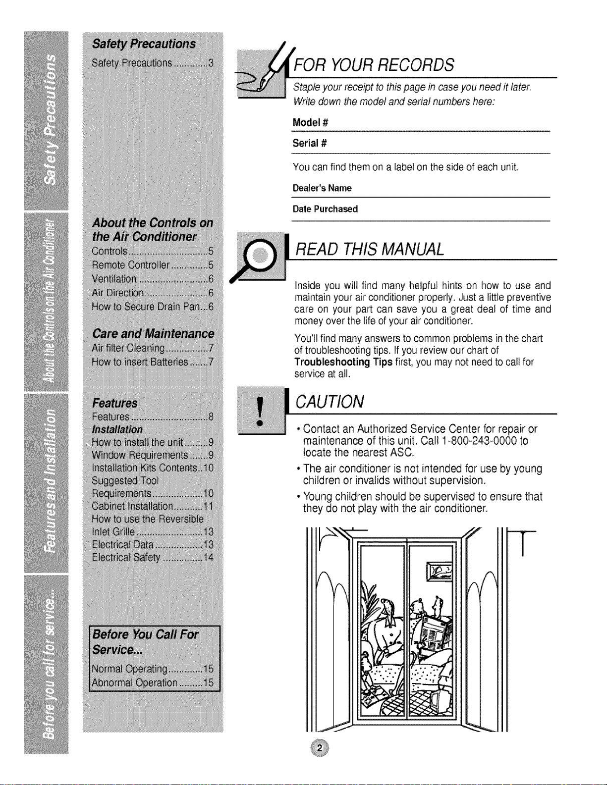
FOR YOURRECORDS
Staple your re.ce_otto this page in case you need it later,
Write down the model and serial numbers here:
Model #
Serial #
You can find them on a label on the side of each unit.
Dealer'sName
DatePurcha_d
READ THIS MANUAL
Inside you will find many helpful hints on how to use and
maintain your air conditioner properly, Just a little preventive
care on your part can save you a great deal of time and
money over the life d your air conditioner,
You'll find many answers to common problems in the chart
of troubleshooting tips. If you review our chart of
Troubleshooting Tips first, you may not need to call for
service at all.
• Contact an Authorized Service Center for repair or
maintenance of this unit. Call 1-800-243-0000 to
locate the nearest ASC.
• The air conditioner _sinot intend_ for use by young
children or invalidswithout supervision.
• Young children should be supervised to ensure that
they do not play with the air conditioner.
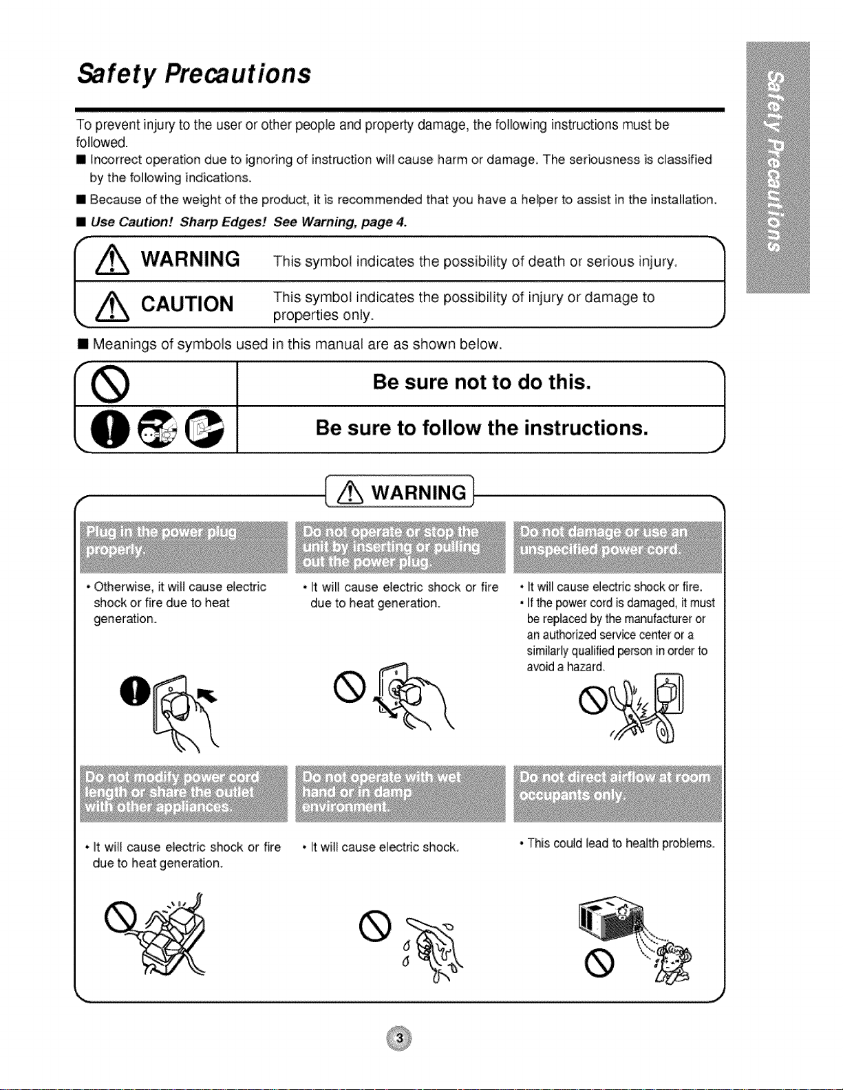
fety Pre utions
To prevent injury to the user or other people and property damage, the following instructions must Ibe
followed.
[] _n_rrect operation due to ignoring of instruction wi!_ cause harm or damage, The seriousness is classified
by the following indications.
[] Because of the weight of the product, it is recommended that you have a hdper to assist in the installation.
[] Use Caution! Sharp Edges! See Warning; page 4.
[] Meanings of symbols used in this manual are as shown below.
Be sure not to do this.
I sure
f
• Otherwise, it will cause electric
shock or fire due to heat
generation.
__ Be to follow the instructions.
[ _ WARNING 1
L J
, It will cause electric shock or fire
due to heat generation.
• It wiil_use electric shockor fire.
• Ifthepowercordisdamaged,_must
replacedbythemanufactureror
an authorizedsewicecenterora
similarlyqualifiedpe_s®inorderto
avoida hazard,
• It will cause dectric shock or fire , Itwil_cause electric shock.
due to heat generation.
®
• This could lead to health problems.

c 1o.1
• It maycause an injury.
• This could iniure the pets or
plants.
• Water may enter the unit
and degrade the
insulation. It may cause
an electric shock.
•Do not use this air conditioner to
preserve precision devices, f_d,
pets, plants, and art objects.
it may cause deterioration of
quali_, etc.
• An oxygen shortage may
occur.
• it may cause an electric shock.
• S[n_ the fan rotates at
high s_ed during
operation, it may cause
an injury.
• It may cause afire or deformation
d the cabinet
• It may cause imperfect
combustion.
• Use caution when handling the
case. Grip it firmly and do not allow
it to slip while holding it,
• Use heavygloves to handlethe caseif
necessary
• DONOT
albw the
caseto slide
yourskin!
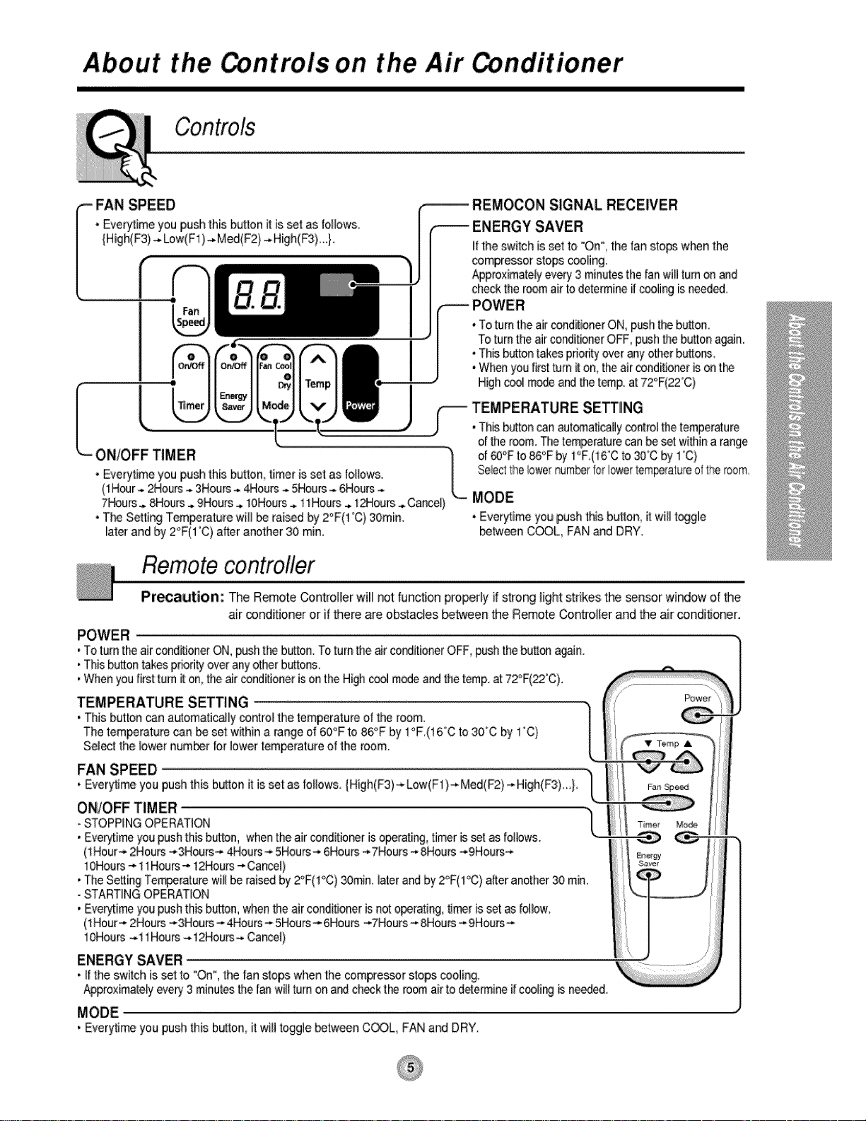
About the ntro, ls on the Air nditioner
SIGNAL RECEWER
if the switch is _t to "On", the fan sto_ wt-_n the
compressor steps coeBng.
Approximatelyevery 3 minutesthe fan will turn on and
check the room air todetermine if cooling isneeded.
• To turn the air cond_ionerON,p_h the bulton.
TOturnthe air conditionerOFF, pushthebutton again.
• Thisbuttontakes priorityover anyother buttons_
• When youfirst turn _ on, the air conditioneris ont_
Highcool modeand the temp. at 72°F(22°C)
TEMPERATURE SE_NG
• This button _n automaticallycontro_the temperature
ON/OFF TIMER
• Everytime you push this button, timer is set as follows.
(1Hour.. 2Hours_.3Hours-,.4Hours-. 5_urs ...6Hours-.
7Hours_ 8Hours_ 9Hours .. 10Hours.. 11Hours.. 1Hours .,.Cancel)
• The Setting Tempsrature wil_be rai_d by 2°F(1%) 30rain.
later and by 2°F(1'C) after another 30 rain,
el the room. The temperaturecan be set within arange
Of@°F to _°F by 1°F,(16"Cto 30% by 1"C)
SelectthelowernumberforIcwertem_ature ofthe room.
MODE
* Everytime you push thisbutton it will toggle
be_een C_L, FAN and DRY.
Remotecontrofler
Pr_aution: The RemoteControllerwill not functionpro_dy ifstrong Hghtstrikesthe _nsor windowof the
air condffioneror ifthere areobstaclesbetweenthe RemoteControllerandthe air conditioner.
• To turn the airconditioner ON, push t_ button. To turn the air cor_itioner OFF, pushthebutt_ a_ino
• This button takespdodty over anyotherbutton&
• When youIirst turn it on,the air conditioneris onthe Highcoo_modea_ the temp, at 72°F(22°C).
TEMPERATURE SETTING
• This button _n automatically controEthetemperature of the room.
The temperature can be set within a range of 60_Fto 86°F by 1°F,(16"C to 30°C by 1"C)
Sei_t the _owernumber tor lower temperatureof the room.
FAN SPEED
• Ever_me you pushthis bu_on it is set as follows, {High(F3)--Low(F1 }_ Med(F2} -_High(F3).}
ON/OFF TIM ER
- STOPPING OPERATION
• Ever:_imeyou push this button, whenthe air conditioner isoperating, timer is_t as {ollows_
(1Hour_ 2Hours _,3Hours- 4Hours_ 5Hours- 6Hou_ -*7Hours -_8Hours ---9Hours_
10Hours- 11Hours_, 12Hours..*Cancel)
• The Setting Te_erature will be raisedby_F(lOC) _min. later and by 2°F(1°C) after another 30 rain,
oSTARTING OPERATION
• Everytime you push this button, when the air conditioner isnot operating, timer isset as re!low
(1Hour-* 2Hou_ _,3Hours_. 4Hou_ _ 5Houm--6Hours ---7Hours_ 8Houm_--9Hours_,
10Hours -,_11Hours-,-12Hours-,*Cance_)
ENERGY SAVER
• Iftheswitchissetto "On",thetanstopswhenthecompressorstopscooling_
Approximatelyeve_ 3minutesthefanwillturnona_ ci]eckt_ ro_ airto determineifcooling_ needed.
Mode
• Everytime you push this b_on_ it wiB togglebetween C_L FAN and DRY.
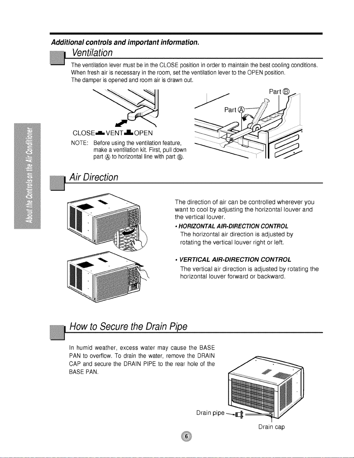
Additional controls and imPortant information.
The ventilation lever must be in the CLOSE position in order to maintain the best cooling _nditions.
When fresh air is necessary in the room, set the ventilation lever to the OPEN position.
The damper is opened and room air is drawn out.
CLOSE_ VENT JL OPEN
NOTE: Before using the ventilation feature,
make a ventilation kit First, pull down
part @ to horizontal line with part (:_.
Air Direction
The direction of air can be controlled wherever you
want to cool by adjusting the horizontal louver and
the ve_ical louver.
•HORIZONTAL AIR.DIRECTION CONTROL
The horizontal air direction is adjusted by
rotating the vertical louver right or left.
• VERTICAL AIR-DIRECTION CONTROL
The vertical air direction is adjusted by rotating the
horizontal louver forward or backward.
How to Secure the Drain
In humid weather, excess water may cause the BASE
PAN to overflow To drain the water, remove the DRAIN
CAP and secure, the DRAIN PiPE to the rear hole of the
BASE PAN.
Drain pipe
Drain cap
and Maintenain
TURN THE AIR CONDITIONER OFF AND REMOVE THE PLUG FROM THE POWER OUTLET.
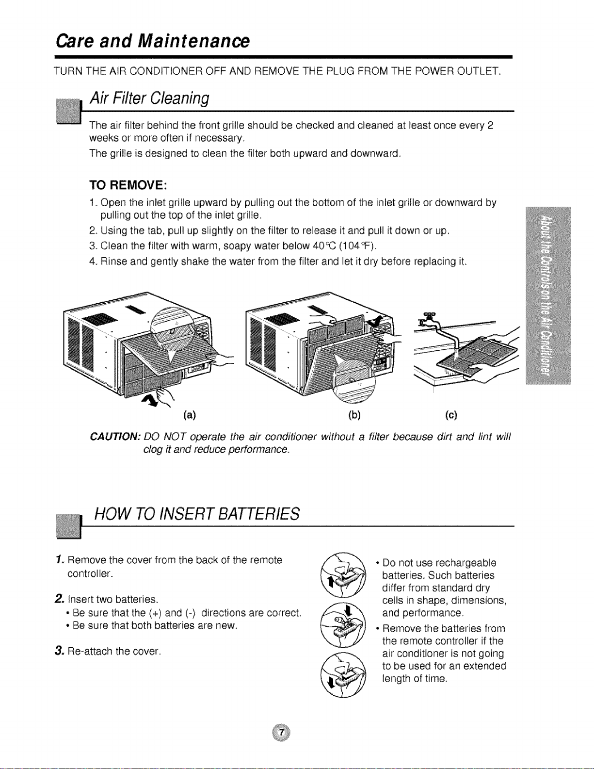
Air Filter Cloaning
The air filter behind the front grille should be checked and cleaned at least once every 2
weeks or more often if necessary.
The grille is designed to clean the filter both upward and downward,
TO REMOVE:
1_Open the inlet grille upward by pulling out the bosom of the inlet grille or downward by
pulling out the top of the inlet grille.
2. Using the tab, pull up slightly on the filter to release it and pull it down or up.
3. Clean the filter with warm, soapy water below 40_ (104_).
4. Rinse and gently shake the water from the filter and let it dry before replacing it.
(a) (b) (c)
CAUTION: DO NOT operate the air conditioner without a filter because dirt and lint will
clog it and reduce performance.
HOW TO INSERT BATTERIES
1. Remove the cover from the back of the remote
controller.
2. Insert two batteries.
• Be sure that the (+) and (-) directions are correct
• Be sure that both bakeries are new.
3. Re-attach the cover.
• Do not use rechargeable
batteries. Such batteries
differ from standard dry
ceils in shape, dimensions,
and performance
° Remove the batteries from
the remote controller if the
air conditioner is not going
to be used for an extended
length of time,
atums
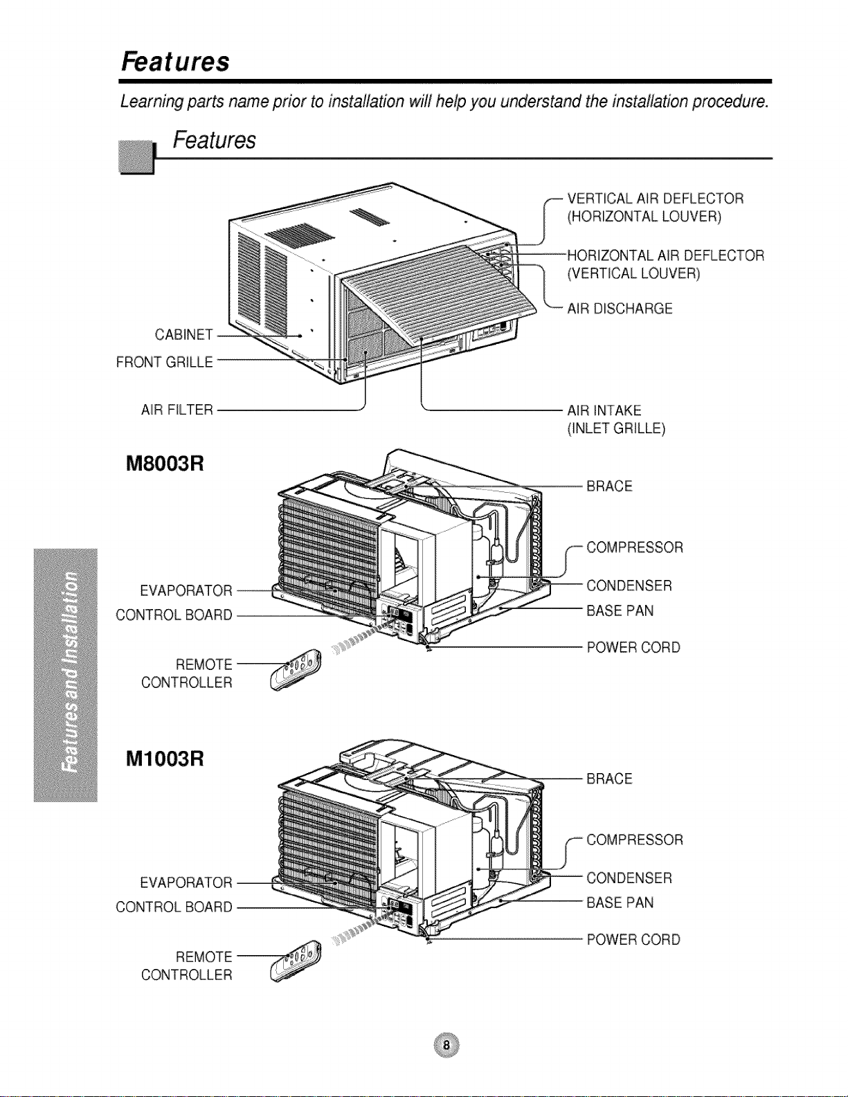
Learning parts name prior to installation will help you understand the installation pmc_edure.
VERTICAL AIR DEFLECTOR
(HORIZONTAL LOUVER)
DRIZONTAL AIR DEFLECTOR
(VERTICAL LOUVER)
AIR DISCHARGE
CABINET
FRONT GRILLE
AIR FILTER " AIR INTAKE
(INLET GRILLE)
BRACE
EVAPORATOR _ ;ER
CONTROL BOARD BASE PAN
POWER CORD
REMOTE_
CONTROLLER
MIOO3R
EVAPORATOR--
CONTROLBOARD
BASE PAN
;ER
REMOTE_
CONTROLLER
POWER CORD
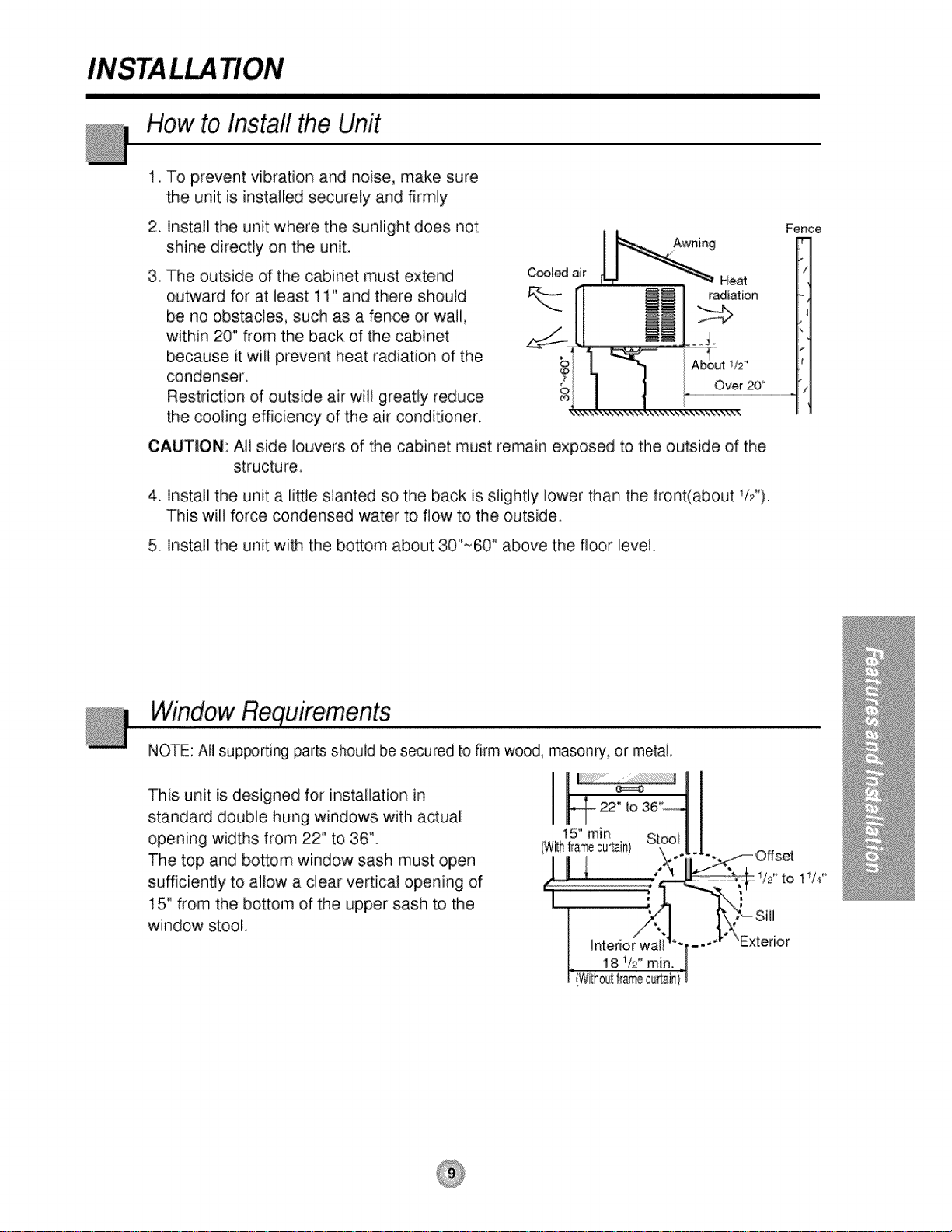
Howto Installthe Unit
.
To prevent vibration and noise, make sure
the unit is installed securely and firmly
25
Install the unit where the sunlight does not
shine directly on the unit.
3_
The outside of the cabinet must extend
outward for at least 11" and there should
be no obstacles, such as a fence or wall,
within 20" from the back of the cabinet
because it will prevent heat radiation of the
condenser.
Restriction of outside air will greatly reduce
the cooling efficiency of the air conditioner.
CAUTION: All side louvers of the cabinet must remain exposed to the outside of the
structure.
4. Install the unit a little slanted so the back is slightly lower than the front(about 1/¢,).
This will force condensed water to flow to the outside.
5. Install the unit with the bottom about 30"~60" above the floor level.
;..J......... ......................................................................,
Fenc_
f
WindowRequirements
NOTE: All sup_rting parts should be secured to firm wood, masonry, or metal.
This unit is designed for installation in
standard double hung windows with actual
opening widths from 22" to 36".
The top and bottom window sash must open
sufficiently to allow a clear vertical opening of
15" from the bottom of the upper sash to the
window stool.
I j ....
(Wi_hflamecurtain}
22" to
15" min
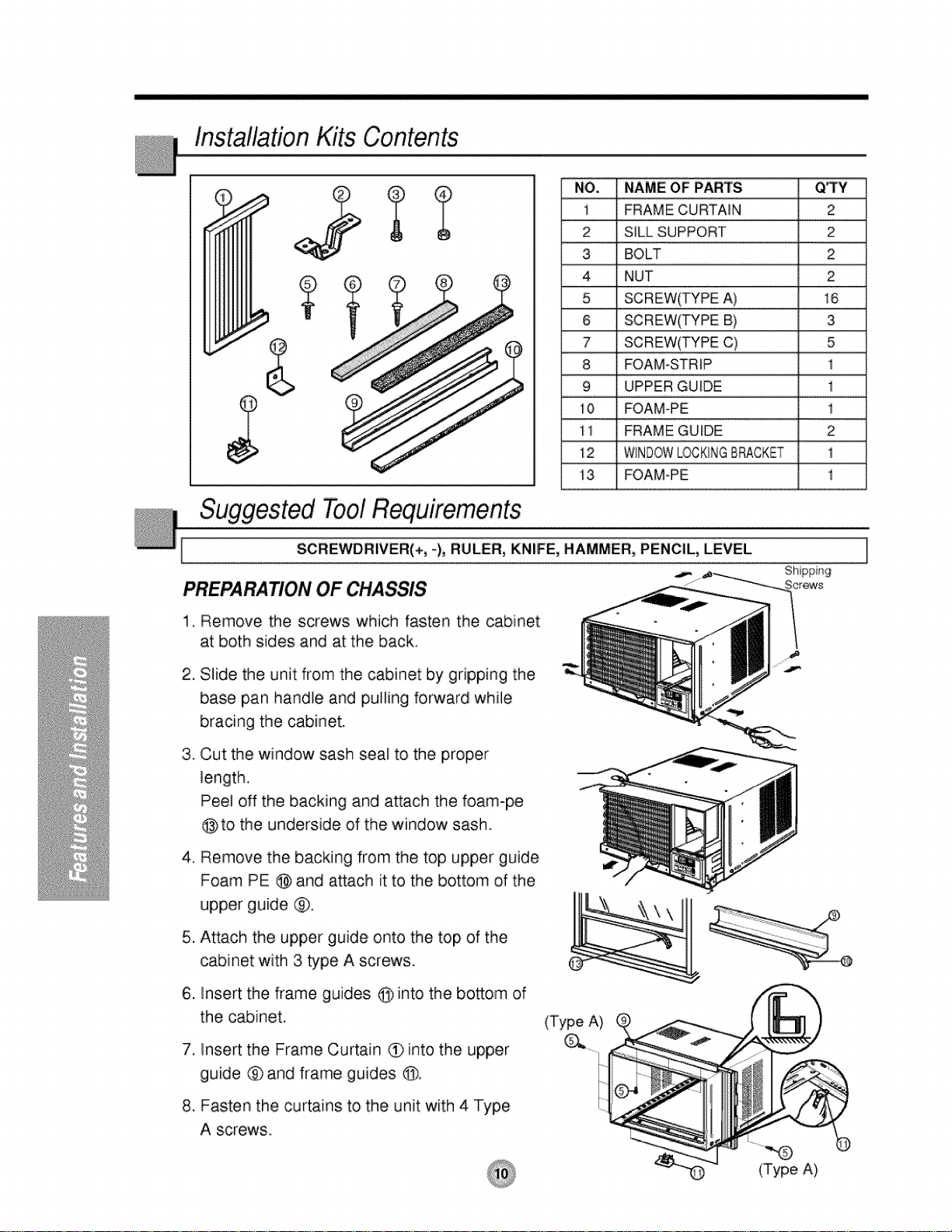
InstallationKits Contents
NO. NAME OF PARTS Q%Y
_
i FRAME CURTAmN 2
2 SILL SUPPORT 2
3 BOLT 2
4 NUT 2
5 SCREW(TYPE A) 16
6 SCREW(TYPE B) 3
7 SCREW(TYPE C) 5
8 FOAM-STRIP 1
9 UPPER GUIDE 1
0 FOAM-PE 1
11 FRAME GUIDE 2
12 WINDOWLOCKINGB_CKET 1
i 3 FOAM-PE 1
Suggested Tool Requirements
I SCREWDRIVER(+, -), RULER, KNIFE, HAMMER, PENCIL, LEVEL
PREPARATION OF CHASSIS
Remove the screws which fasten the cabinet
at both sides and at the back.
2_
Slide the unit from the cabinet by gripping the
base pan handle and pulling forward while
bracing the cabinet.
,
Cut the window sash seal to the proper
length.
Peel off the backing and attach the foam-pe
@ to the underside of the window sash.
4_
Remove the backing from the top upper guide
Foam PE @ and attach it to the bottom of the
upper guide ®.
.
Attach the upper guide onto the top of the
cabinet with 3 type A screws.
,
Insert the frame guides @ into the bottom of
the cabinet.
,
Insert the Frame Curtain _ into the upper
guide ® and frame guides @.
(Type A)
8. Fasten the curtains to the unit with 4 Type
A screws
(Type A)
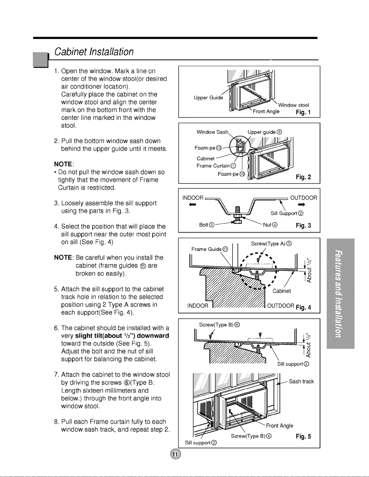
CabinetInstallation
1. Open the window. Mark a line on
center of the window stool(or desired
air conditioner location).
Carefully place the cabinet on the
window stool and align the center
mark on the bottom front with the
center line marked in the window
stool.
2. Pull the bottom window saslh down
behind the upper guide until it meets.
• Do not pull the window sash down so
tightly that the movement of Frame
Curtain is restricted.
3. Loosely assemble the sill support
using the parts in Fig. 3.
Upper Guide
Window stool
Front Angie Fig, 1
Window Sash
Foam-
Frame Cumin 0
Foam-pe@
4. Select the position that will place the
sill support near the outer most point
on sill (See Fig. 4)
NOTE: Be careful when you install the
cabinet (frame guides @ are
broken so easily).
5. Attach the sill support to the cabinet
track hole in relation to the selected
position using 2 Type A screws in
each support(See Fig. 4).
6. The cabinet should be installed with a
very slight tilt(about 1/2") downwaird
toward the outside (See Fig. 5).
Adjust the bolt and the nut of sill
support for balancing the cabinet
7. Attach the cabinet to the window stool
by driving the screws ®(Type B:
Length sixteen millimeters and
below.} through the front angle into
window stool,
_rew(Type A) Q
_rew(Type B)
SillsuppodQ
Sashtrack
8. Pull each Frame curtain fully to each
window sash track, and repeat step 2.
Front Angle
Screw(Type B)Q
Sill suppo_Q
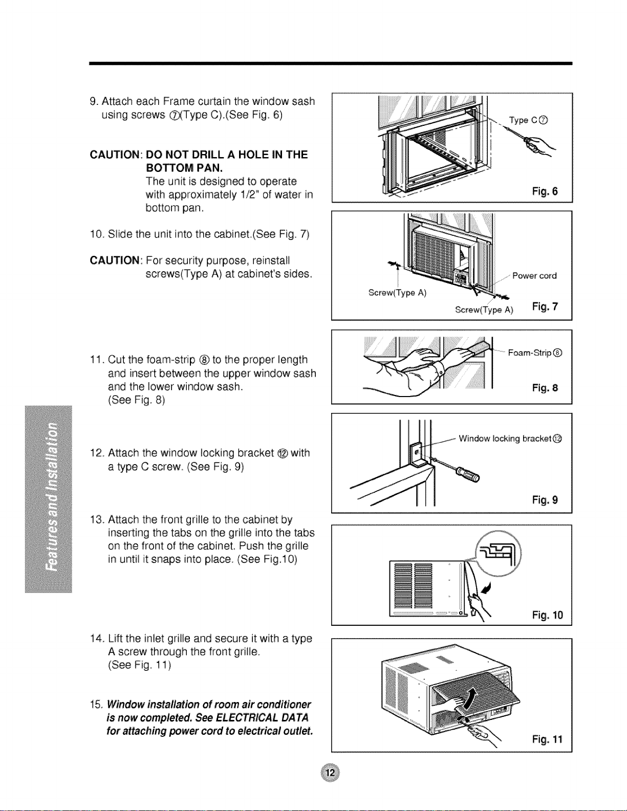
9. Attach each Frame curtain the window sash
using screws _Type C),(See Fig, 6)
CAUTION: DO NOT DRILL A HOLE IN THE
BOSOM PAN,
The unit is designed to operate
with approximately 1/2" of water in
bottom pan,
10. Slide the unit into the cabinet(See Fig, 7)
CAUTION: For security purpose, reinstall
screws(Type A) at cabinet's sides.
........Power cord
11. Cut the foam-strip ® to the proper length
and insert between the upper window sash
and the lower window sash.
(See Fig. 8)
12. Attach the window locking bracket @ with
a type C screw (See Fig. 9)
13. Attach the front grilte to the cabinet by
inserting the tabs on the grille into the tabs
on the front of the cabinet, Push the grille
in until it snaps into place. (See Fig,10)
Screw(Ty_ A)
f
Screw(Type A)
F_m-Strip Q
Window locking bracket @
14 Lift the inlet gdlle and secure it with a type
A screw through the front grille,
(See Fig. 11)
15, Window installation of morn air conditioner
is now completed, See ELECTRICAL DATA
for attaching _wer cord to electrical outlet,
Fig, 10
Fig. 11
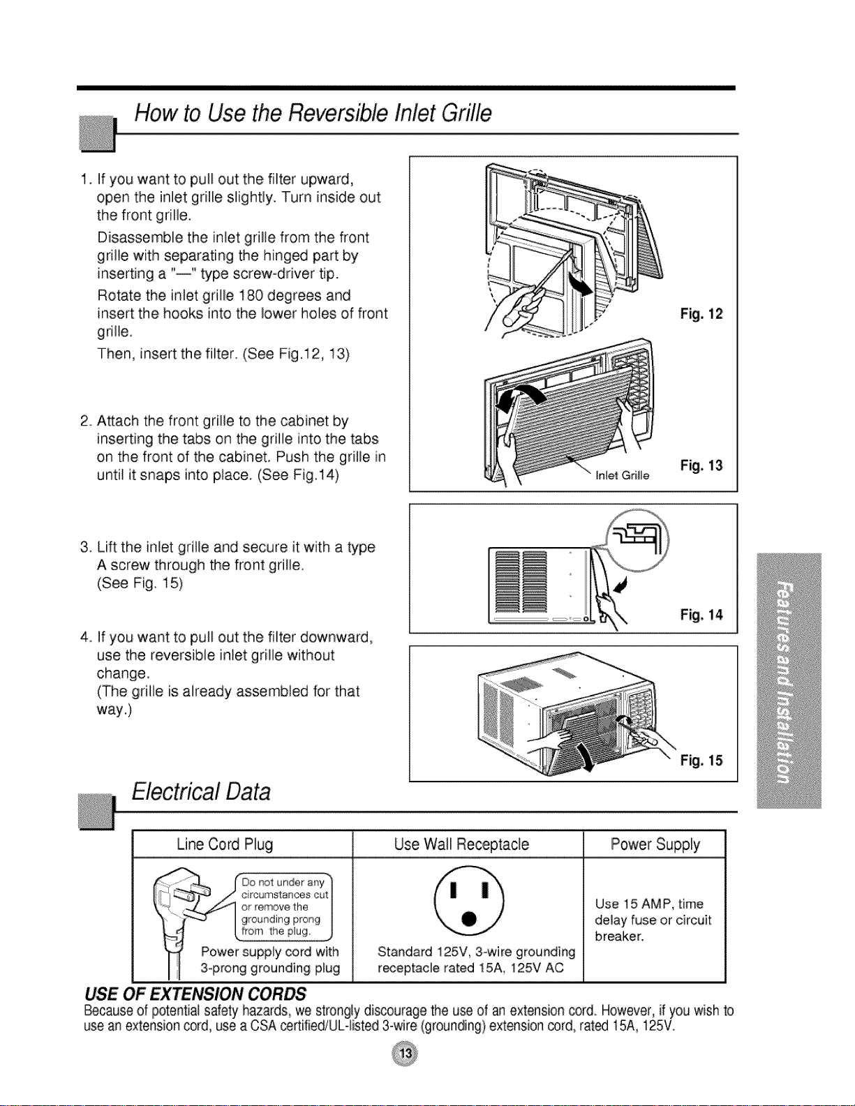
How to Use the Reversible,Inlet Grille
1. If you want to pull out the filter upward,
open the inlet grille slightly. Turn inside out
the front grille.
Disassemble the inlet grille from the front
grille with separating the hinged part by
inserting a "--" type screw-driver tip.
Rotate the inlet grille 180 degrees and
insert the hooks into the lower holes of front
grille
Then, insert the filter. (See Fig.12, 13)
2 A_ach the front grille to the cabinet by
inserting the tabs on the grifle into the tabs
on the front of the cabinet, Push the grille in
until it snaps into place (See Fig.14)
!
7
Fig. 12
Fig, 13
3. Lift the inlet grille and secure it with a type
A screw through the front grille.
(See Fig. 15)
Fig, 14
4 if you want to pull out the filter downward,
use the reversible inlet grille without
change.
(The grille is already assembled for that
way.)
Fig. 15,
Bectrical Data
Line Cord Plug Use Wall Receptacle Power Supply
_T J z/ circumstances out
-./.._ or remove the Use 15 AM P time
>-_J I grounding prong delay fuse or circuit
......._ l[)o r_otur'der ar_Y
i breaker.
USE OF EXTENSION CORDS
Because of potential safety hazards, we strongly discourage the use of an extension cord_However, if you wishto
use an extension cord, use a CSA certifiediUL-listed 3-wire (grounding) extension _rd, rated 15A, i25V.
[..from the plug,
Power supply €oid with
3oprong grounding plug
Standard 125V, 3-wire grounding
r_eptacle rated 15A, 125V AC
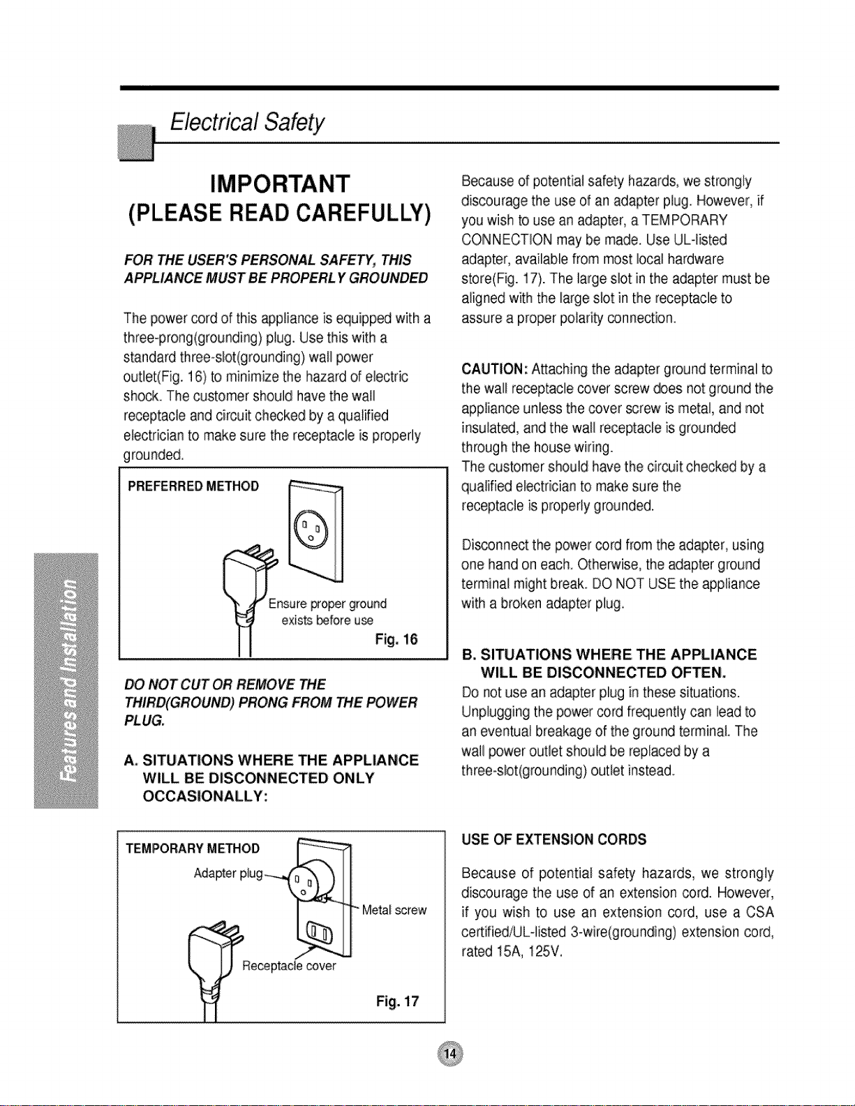
ElectricalSafety
(PLEASE READ CAREFULLY)
FOR THE USER'S PERSONAL SAFETY, THIS
APPLIANCE MUST BE PROPERI_ Y GROUNDED
The power cord of this appliance is equipped with a
three-prong(grounding) plug. Use this with a
standard three-slot(grounding) wall power
outlet(Fig. 16) to minimize the hazard of electric
shock. The customer should have the wall
receptacle and circuit checked by a qualified
electrician to make sure the r_eptacle is properly
grounded,
PREFERREDMETHOD
Because of potential safety hazards, we strongly
discourage the use of an adapter plug. However, if
you wish to use an adapter, a TEMPORARY
CONNECTION may be made. Use ULqisted
adapter, available from most local hardware
store(Fig. 17). The large slot in the adapter must be
aligned with the large slot in the receptacle to
assure a proper polari_ connection.
CAUTION: A_aching the adapter ground terminal b
the wall receptacle _ver screw does not ground the
appliance unless the cover screw is metal, and not
insulated, and the wall receptacle is grounded
through the house wiring.
The customer should have the circuit checked by a
qualified electrician to make sure the
receptacle is properly grounded.
nsureFoper ground
exists _fore u_
Fig. 16
DO NOT CUT OR REMOVE THE
OUND) PRONG FROM THE POWER
PLUG,
A. SITUATIONS WHERE THE APPLIANCE
WILL BE DISCONNECTED ONLY
OCCASIONALLY:
Metal screw
Di_onnect the power cord from the adapter, using
one hand on each_ Otherwise, the adapter ground
terminal might break DO NOT USE the appliance
with a broken adapter plug,
B. SITUATIONS WHERE, THE APPLIANCE
WILL BE DISCONNECTED OFTEN.
Do not use an adapter piug in these situations.
Unplugging the power _rd fr_uent]y can lead to
an eventual breakage of the ground terminal The
wail power outlet should be replaced by a
three-slot(grounding) outlet instead.
USE OF EXTENSION CORDS
Because of potential safety hazards, we strongly
discourage the use of an extension cord. However,
if you wish to use an extension cord, use a CSA
certified/UL4isted 3-wire(grounding) extension cord,
rated 15A, 125V,
Fig. 17
 Loading...