

Page 1

1-1.
INTRODUCTION
1.
GENERAL INFORMATION
The Model
many quality
delayed sweep, and a
7040A
features:
shown
in
Figure
1-1,
is a
40
MHz dual-trace oscilloscope with
wide bandwidth, high sensitivity, dual timebases with
TV
sync separator. Moreover, the large CRT has an illumin-
ated internal graticule for parallax-free measurements and photographic applications.
1-2.
SPECIFICATIONS
Specifications for the Model
Vertical Amplifiers (Ch.l
Bandwidth
DC
(-3
coupled
dB)
& 2)
7040A
Model
oscilloscope are given in Table
Table
7040A
1-1
SPECIFICATIONS
DC
to
40
MHz normal
DC
to 7
MHz
magnified
1-1.
AC
coupled
10
Hz to
10
Hz to 7
40
MHz normal
MHz
magnified
Risetime 8.8 nS normal
50
nS magnified
Deflection
Coefficients 5 m V / div to 5 V / div
in
10
calibrated steps
of a 1-2-5 sequence. Continuously variable
between steps, highest uncalibrated deflection
12.5
V /
div.
factor is at least
5 X magnifier
adds 1 m V / div and 2 m V / div steps for frequencies up to 7
MHz.
Accuracy ± 3 %normal; ± 5 % magnified
Input Impedance Approx. 1 megohm
300
Maximum Input Voltage
Input Coupling
V (DC + peak
500
V peak
AC,
DC,
or ground
AC
in
parallel with
AC)
below 1 kHz
30
pF
Page 2
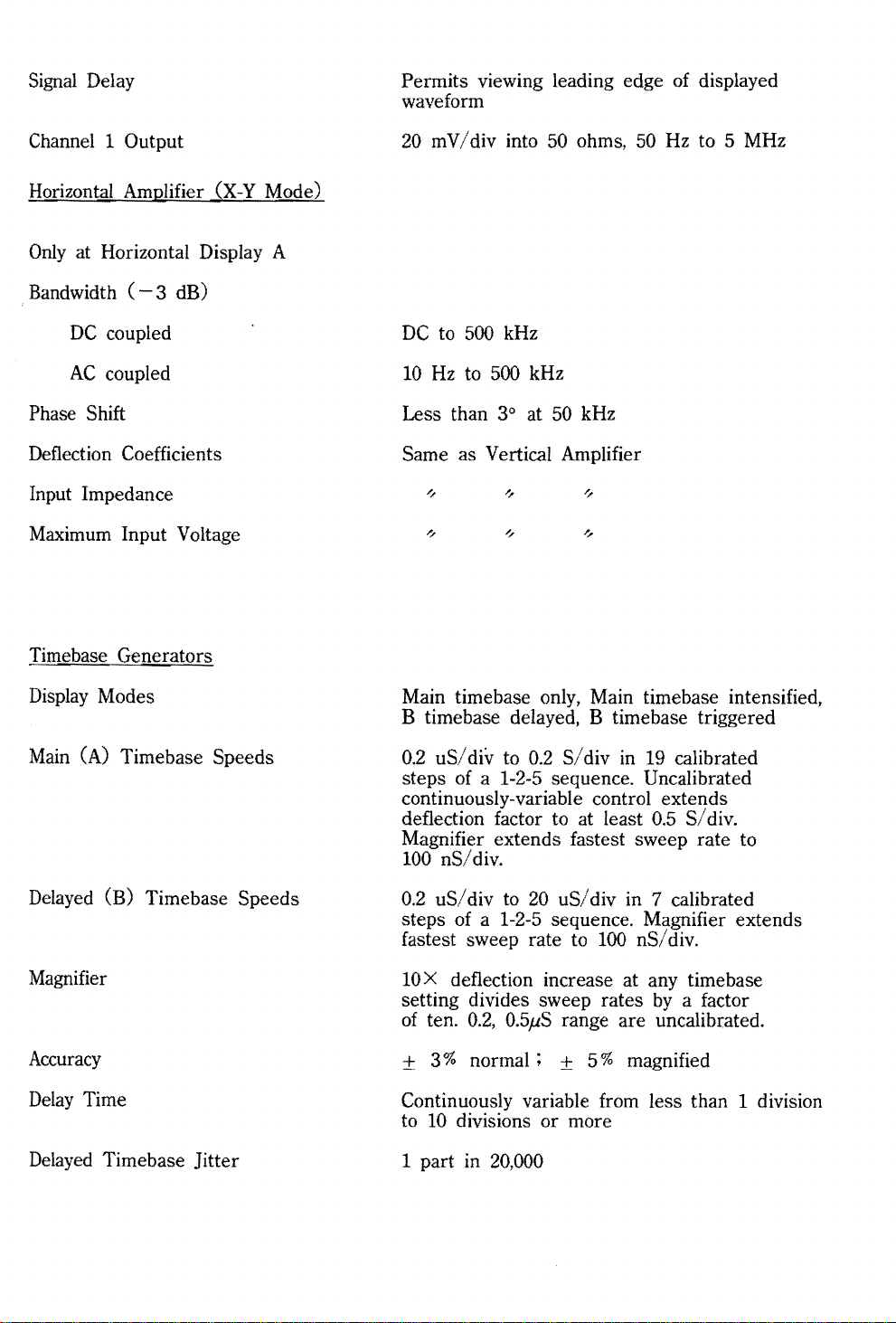
Signal
Delay
Permits viewing leading edge of displayed
waveform
Channel 1 Output
Horizontal Amplifier
Only
at Horizontal Display A
Bandwidth
DC
AC
(-
3 dB)
coupled
coupled
(X-Y
Phase Shift
Deflection Coefficients
Input Impedance
Maximum Input Voltage
Timebase Generators
Mode)
20 m V / div into 50 ohms, 50
DC
to
500
kHz
10
Hz
to
500
kHz
Less than 3° at
50 kHz
Same as Vertical Amplifier
Hz
to 5 MHz
Display
Main
Modes
(A) Timebase Speeds
Delayed (B) Timebase Speeds
Magnifier
Accuracy
Delay
Delayed
Time
Timebase Jitter
Main timebase only, Main timebase intensified,
B timebase delayed, B timebase triggered
0.2
uS/
steps
div to 0.2 S/div in
of
a 1-2-5 sequence. Uncalibrated
19
calibrated
continuously-variable control extends
deflection factor to at least
0.5
S/
div.
Magnifier extends fastest sweep rate to
100
nS/div.
0.2
uS/
div
to
20
uS/
div in 7 calibrated
steps of a
fastest sweep rate to
10 X deflection increase at any time base
setting divides sweep rates
of
ten. 0.2, 0.5;B range are uncalibrated.
± 3%
1-2-5 sequence. Magnifier extends
100
nSf div.
by
a factor
normal;
± 5% magnified
Continuously variable from less than 1 division
to
10 divisions or more
1 part in
20,000
Page 3
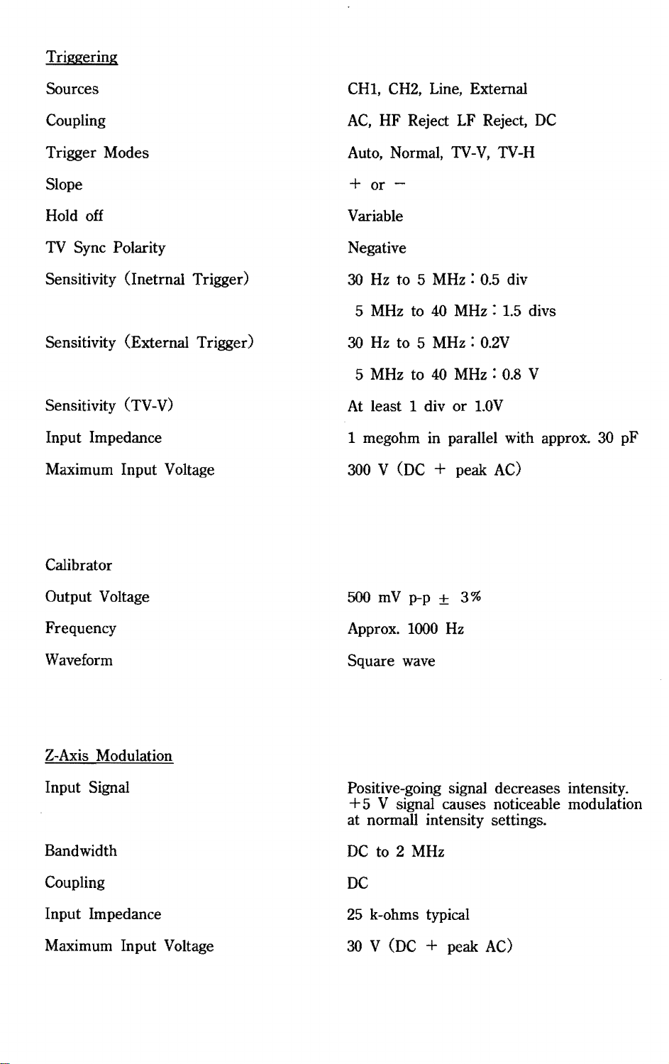
Triggering
Sources
CHI,
CH2,
Line, External
Coupling
Trigger Modes
Slope
Hold off
TV
Sync Polarity
Sensitivity (Inetrnal Trigger)
Sensitivity (External Trigger)
Sensitivity (TV-V)
Input Impedance
Maximum Input Voltage
AC,
Auto,
HF Reject
Normal,
LF
Reject,
TV-V,
DC
TV-H
+ or -
Variable
Negative
30
Hz
to 5 MHz :
5
MHz
to
40
30
Hz
to 5
MHz:
5
MHz
to 40
At
least 1 div or
1 megohm in parallel with approx. 30 pF
300
V (DC + peak
0.5
div
MHz:
MHz : 0.8
1.5
0.2V
l.OV
AC)
divs
V
Calibrator
Output Voltage
Frequency
Waveform
Z-Axis
Input Signal
Bandwidth
Coupling
Input Impedance
Maximum Input Voltage
Modulation
500
mV
p-p ± 3%
Approx.
Square
Positive-going signal decreases intensity.
1000
wave
Hz
+5 V signal causes noticeable modulation
at normall intensity settings.
DC
to 2
MHz
DC
25
k-ohms typical
30 V (DC
+ peak
AC)
Page 4
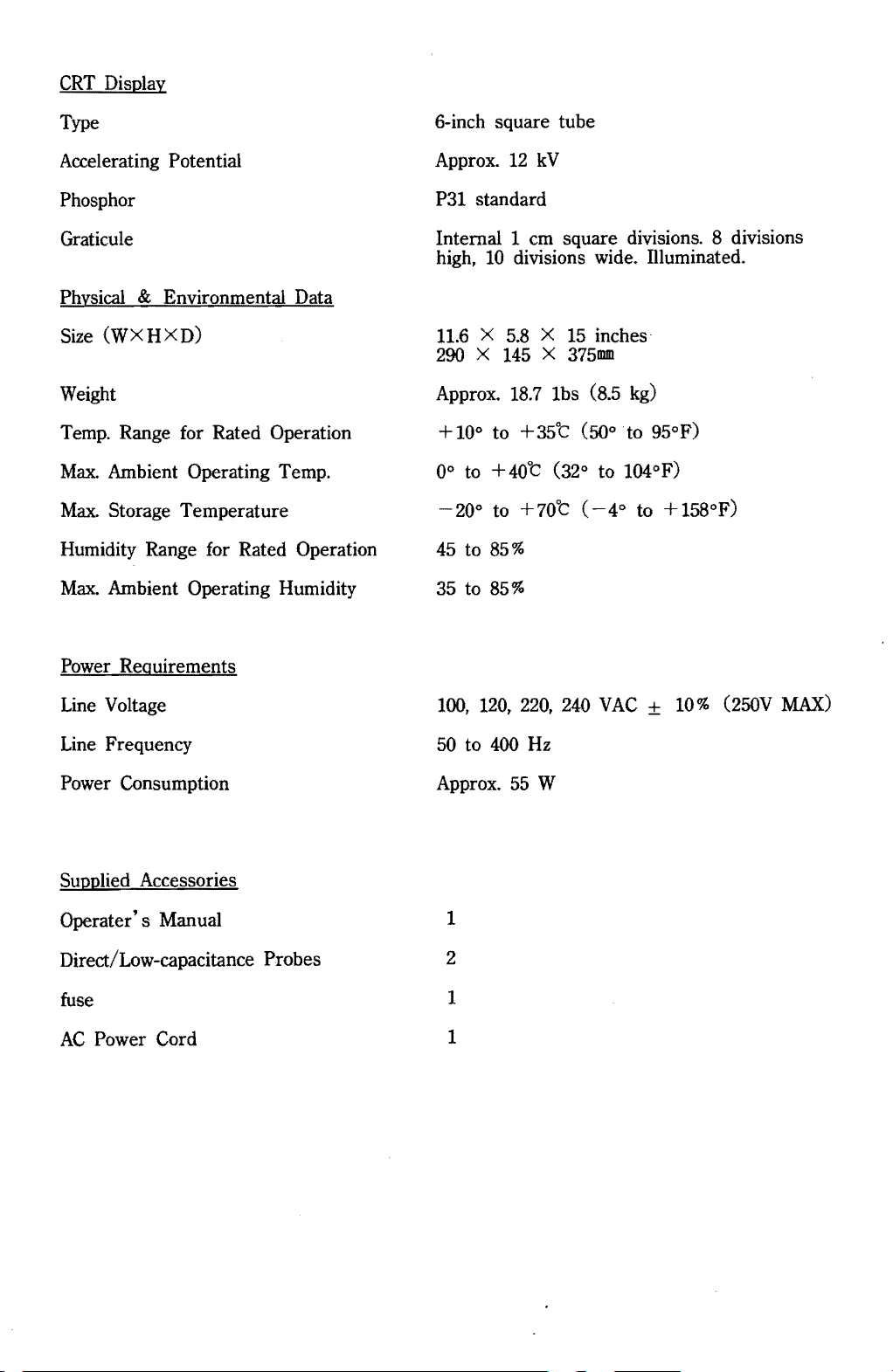
CRT
Display
Type
Accelerating Potential
Phosphor
Graticule
Physical
Size
& Environmental Data
(WXHXD)
Weight
Temp.
Max.
Max.
Range for Rated Operation
Ambient Operating Temp.
Storage Temperature
Humidity Range for Rated Operation
Max.
Ambient Operating Humidity
6-inch square tube
Approx.
P31
Internal 1
high,
11.6 X 5.8 X 15
12
kV
standard
cm
square divisions. 8 divisions
10
divisions wide. Illuminated.
inches·
290 X 145 X 375mm
Approx.
+10°
0° to
-20°
45
35
to
to
18.7
to
+35't
+40't
to
+70't
85%
85%
1bs (8.5 kg)
(50° to 95°F)
(32° to 104°F)
(-4°
to +158°F)
Power Requirements
Line
Voltage
Line
Frequency
Power Consumption
Supplied Accessories
Operater's Manual
Direct/Low-capacitance Probes
fuse
AC
Power Cord
100, 120,
50
to
400
Approx.
1
2
1
1
220,
55
Hz
W
240
VAC ± 10%
(25OV
MAX)
Page 5
,00-~--~-+--+--+--+--4--4-~--~
.b
....
FIGU
RE
2 -
1.
FRONT-PAN
EL
30
1IlL-_~32
ITEMS
0
0
~
GoldStor
WARNING
FIGURE 2 -
OSCILLOSCOPE
OS-7040A
Precision
CO.,Ltd.
I.IADE
IN
KOREA
POWER
C(JtSUWPTlON:
2.
OUWUT
~
®
APPR025W
REAR-PAN
EL
0
0
ITEMS
0 0
0
0
0
0
Page 6

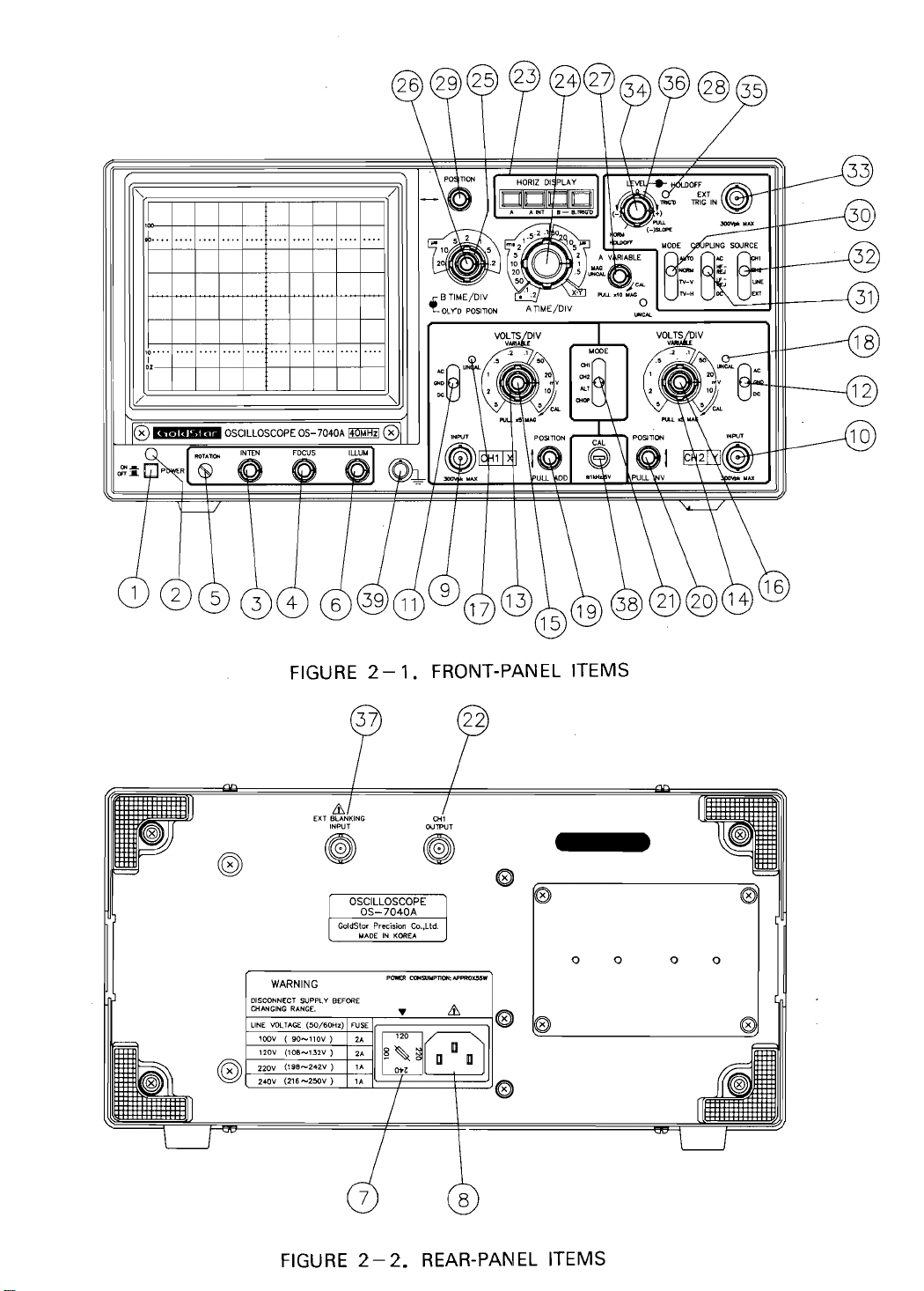
2.
OPERATING INSTRUCTIONS
This section contains the information needed to operate the Model
utilize
it in a variety of basic and advanced measurement procedures. Included
are
the
identification and function of controls, connectors, and indicators,
7040A
startup procedures, basic operating routines, and selected measurement procedures.
2-1.
FUNCTION
OF CONTROLS, CONNECTORS,
AND
INDICATORS
Before turning this instrument on, familiarize yourself with the controls,
conne,ctors,
following
2-1-1
(1)
POWER
(2)
POWER
indicators, and other features described in this section. The
descriptions are keyed to the items called out in Figures 2-1 and 2-2.
Display
Item
and Power Blocks
switch
lamp
Function
Push in to turn instrument power on and
Lights when power is on.
and i
off.
(3)
INTEN
(4)
FOCUS
(5)
ROTATION
(6)
ILLUM
(7)
Voltage
(8)
Power
control
control
control
control
Selector
Connector
Adjusts the brightness of the CRT display.
Clockwise rotation increases brightness.
To obtain maximum trace sharpness.
Allows screwdriver adjustment
of
trace
alignment with regard to the horizontal
of
the
graticule lines
CRT.
To adjust graticule illumination for
photographing the CRT display.
Permits changing the operating voltage range.
of
the
Permits removal or replacement
AC
power cord.
Page 7
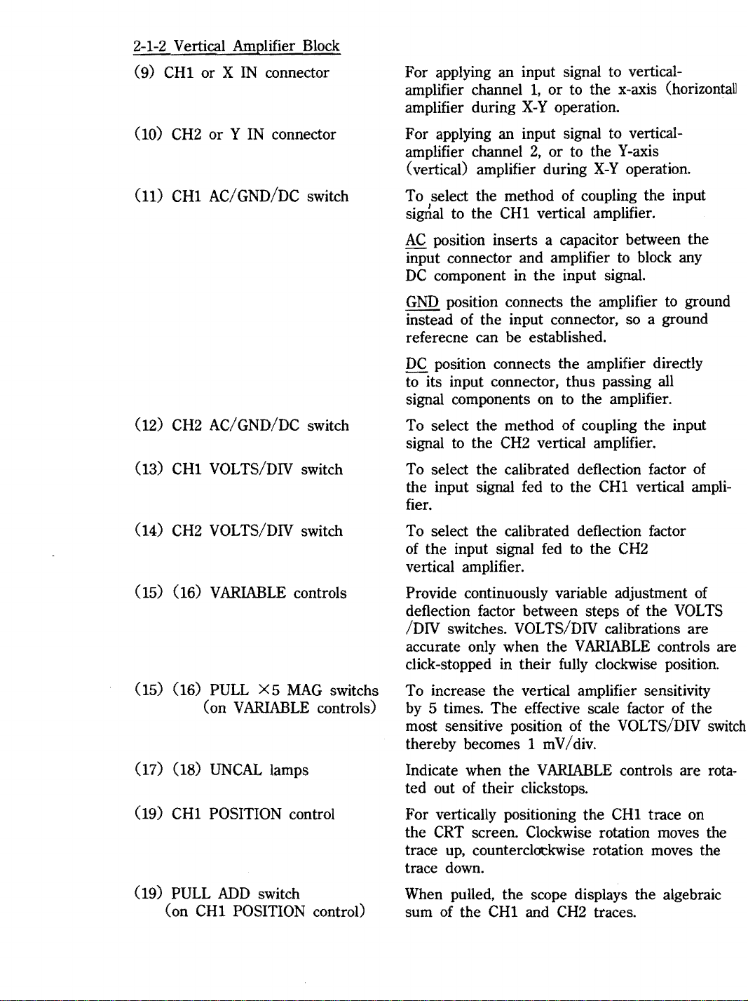
2-1-2
Vertical Amplifier Block
CH1
(9)
(10) CH2
CH1
(11)
CH2
(12)
(13)
CH1
or X
IN
connector
or Y IN
AC/GND/DC switch
AC/GND/DC switch
VOLTS/DIV switch
connector
For applying an input signal to verticalamplifier
amplifier during
For applying an input signal to verticalamplifier channel
(vertical) amplifier during
To select the method of coupling the input
sigrial to the
AC
input connector and amplifier
DC
GND
instead of the input connector, so a ground
referecne can be established.
DC
to its input connector, thus passing all
signal components on
To select the method of coupling the input
signal
To select the calibrated deflection factor of
the input signal fed to the
fier.
channell,
CH1
position inserts a capacitor between the
component
position connects the amplifier
position connects the amplifier directly
to
the
CH2
or to the x-axis (horizontal]
X-Y
operation.
2,
or to the Y-axis
X-Y
operation.
vertical amplifier.
to
block any
in
the input signal.
to
the amplifier.
vertical amplifier.
CH1
vertical
to
ground
ampli-
(14)
CH2
(15) (16)
(15) (16)
(17) (18)
(19)
CH1
PULL
(19)
CH1
(on
VOLTS/DIV switch
VARIABLE
PULL
VARIABLE
( on
UNCAL
POSITION control
ADD
POSITION control)
X5
MAG
lamps
switch
controls
controls)
switchs
To select the calibrated deflection factor
fed
to
the
of the input signal
vertical amplifier.
Provide continuously variable adjustment of
deflection factor between steps of the
/DIV switches. VOLTS/DIV calibrations are
accurate only when the
click-stopped
To increase the vertical amplifier sensitivity
by
5 times. The effective scale factor of the
most sensitive position of the VOLTS/DIV
thereby becomes 1 m V /
Indicate when the
ted out of their clickstops.
For vertically positioning the
CRT
the
up,
trace
trace down.
When pulled, the scope displays the algebraic
sum of the
in
their fully clockwise position.
screen. Clockwise rotation moves the
counterclockwise rotation moves the
CH1
and
VARIABLE
div.
VARIABLE
CH2
CH2
VOLTS
controls are
controls are rota·
CH1
trace on
traces.
switch
Page 8
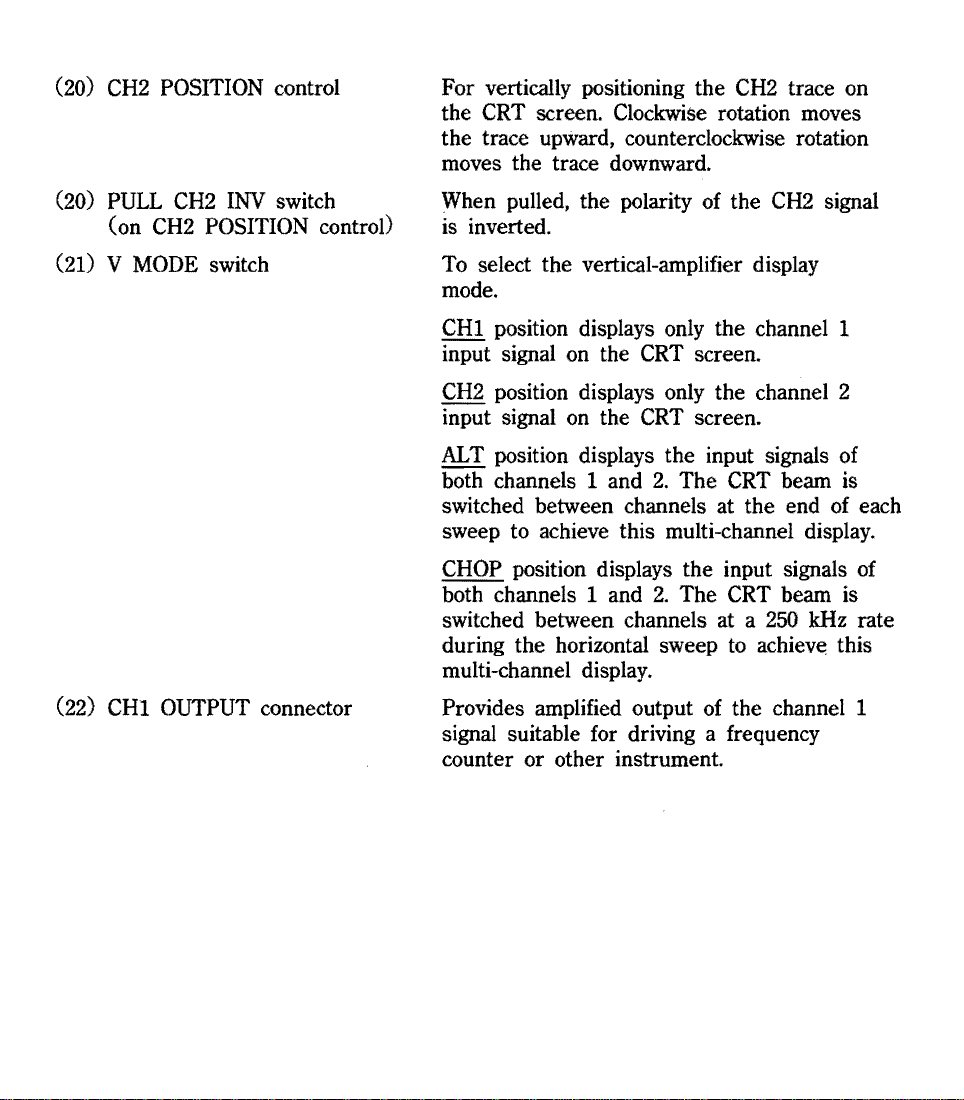
(20)
(20)
CH2
POSITION control
PULL
(on
CH2
CH2
POSITION control)
INV
switch
For vertically positioning the
the
CRT
screen. Clockwise rotation moves
CH2
trace on
the trace upward, counterclockwise rotation
moves the trace downward.
CH2
When pulled, the polarity of the
signal
is inverted.
(21) V
MODE
switch
(22) CHI OUTPUT connector
To
select the vertical-amplifier display
mode.
CHI position displays only the channel 1
CRT
CRT
2.
screen.
screen.
The
CRT
beam is
input signal on the
CH2
position displays only the channel 2
input signal on the
AL
T position displays the input signals of
both channels 1 and
switched between channels at the end of each
sweep to achieve this multi-channel display.
CHOP
both channels 1 and
switched between channels at a
position displays the input signals of
2.
The
CRT
beam is
250
kHz rate
during the horizontal sweep to achieve this
multi-channel display.
Provides amplified output of the channel 1
signal suitable for driving a frequency
counter or other instrument.
Page 9

2-1-3
Sweep and Trigger Blocks
(23)
HORIZ
DISPLAY
switches
To select the sweep mode.
A pushbutton sweeps the CRT at the main (A)
timebase rate when pressed.
(24) A TIME/DIV switch
(25) B TIME/DIV switch
(26)
DELAY
TIME POS control
A INT pushbutton sweeps the CRT at the main
timebase rate when pressed, and the B timebase
intensifies a section
location
by
B pushbutton sweeps the CRT at the rate selected
by
determined
DELAY
B TRIG'D pushbutton sweeps the CRT at the rate
selected
triggered
the delay time determined
switch and the
To select either the calibrated sweep rate of the
main (A) timebase, the delay-time range for
delayed-sweep operation, or
To select the calibrated sweep rate of the
delayed (B) timebase.
To determine the exact starting point within the
A time base delay range at which the B timebase
will
of
the intensified section
the
DELAY
the B TIME/DIV switch, after a delay
by
TIME POS controL
by
the B TIME/DIV switch when
by
the first trigger pulse occuring after
begin sweeping.
of
the trace(s). The
is
determined
TIME POS controL
the A TIME/DIV switch and the
by
the A TIME/DIV
DELAY
TIME POS controL
X-Y
operation.
(A)
(27) A
(27) PULL X
(28)
(29) Horizontal POSITION control
VARIABLE
(on A
UNCAL
VARIABLE
10
lamp
control
MAG
switch
control)
Provides continuously variable adjustment
sweep rate between steps
TIME/DIV calibrations are accurate only when
A
VARIABLE
To expand the horizontal deflection
thus increasing horizontal sensitivity
for
X-Y
sweep speed
Indicates when A
of
its click-stopped position.
To adjust the horizontal position
displayed on the
the traces
tion moves the traces
control
operation, and increasing the effective
by
10
VARIABLE
CRT.
to
the right, counterclockwise rota-
of
the A TIME/DIV
is
click-stopped fully
times.
controls rotated
Clockwise rotation
to
the left.
of
the traces
by
10 times,
by
10 times
of
switdn
clockwise
moves
the
out
Page 10

(30)
Trigger
(31)
Trigger COUPLING switch
MODE
switch
To select
AUTO position selects free-running sweep where
a baseline is displayed in the absense of a
signal. This condition automatically reverts
to triggered sweep when a trigger signal of
Hz
or higher is received and other trigger
controls are properly set.
NORM position produces sweep only when a trigger
signal is received and other controls are properly set.
requirement is missing. This mode must be used
when
TV-V position is used for observing a composite
video signal
TV-H position is used for observing a composite
video signal
To select the frequency characteristics of the
trigger-circuit coupling.
AC
position inserts a large capacitor in the
trigger-coupling chain to remove and
ponent from the trigger signal.
the
sweep triggering mode.
No
trace is visible if any trigger
the
signal frequency is 25
at
the
frame rate.
at
the
line rate.
Hz
or lower.
DC
25
com-
(32) Trigger SOURCE switch
HF
REJ
position inserts a filter in the triggercoupling chain that removes signal components
higher than 4 kHz. Use this position to eliminate high-frequency noise.
REJ
LF
signal components lower in frequency than 4 kHz.
Use this position to eliminate low-frequency
noise
DC
modification. Use this setting when triggering
from a very low-frequency signal or a
To conveniently select
CHI
the trigger source.
CH2 position selects the channel 2 signal
the trigger source.
LINE position selects a trigger derived from the
AC
bilize display line-related components of a signal
even
components of the signaL
position inserts a filter that removes
or
undesired trigger signals.
position passes the trigger signal without
DC
level.
the
trigger source.
position selects the channel I signal as
as
power line. This permits
if
they are very small compared to other
the
scope to sta-
EXT position selects
EXT TRIG
IN
connector.
the
signal applied to
the
Page 11

(33) EXT TRIG
IN
connector
For applying external trigger signal to the
trigger circuits.
(34) Trigger LEVEL control
(34) Trigger SLOPE switch
(on LEVEL control)
(35) TRIG'D lamp
(36)
HOLD
OFF control
To select the trigger-signal amplitude at which
triggering occurs. When rotated clockwise. the
trigger point moves toward the positive peak
the trigger signal. When this control
is
of
rotated
counterclockwise. the trigger point moves toward
the negative peak
To select the positive
of
the trigger signal.
or
negative slope of the
trigger signal for initiating sweep. Pushed
in. the switch selects the positive
(+)
slope.
When pulled, this switch selects the negative
(-)
slope.
is
Lights when the sweep generator
being trig-
gered.
Allows
by
triggering on certain complex signals
changing the hold
off
(dead) time of the
main (A) sweep. This avoids triggering on
intermediate trigger points within the repetition cycle
of
the desired display. The holdoff
time increases with clockwise rotation.
NORM
rotation that
is a position"at full counterclockwise
is
used for ordinary signals.
2-1-4 Miscellaneous Features
(37) EXT BLANKING INPUT connector
(38)
CAL
connector
(39) Ground connector
For applying signal to intensity modulate the
CRT.
Trace brightness is reduced with a posi-
tive signal, and increased with a negative signal.
of
Provides a fast-rise square wave
precise
amplitude for probe adjustment and vertical
amplifier calibration.
Provides an attachment point for a separate
ground lead.
Page 12

2-3.
BASIC
OPERATING PROCEDURES
The following paragraphs in this section describe
beginning with the most elementary operating modes, and progressing to the less
frequently-used
2-3-1 Signal Connections
There are three methods
observe. They are : a simple wire lead, coaxial cable, and scope probes.
A simple lead wire may be sufficient when the signal level is high and the source
impedance
up hum and noise ; this distorts the ovserved signal when the signal level is
Also,
there is the problem
nectors. A binding post-to
Coaxial cable is
and/or
low
(such as TTL circuitry), but is not often used. Unshielded wire picks
complex modes.
of
connecting an oscilloscope to the signal you with to
of
making secure mechanical connection to the input con-
BNC
adapter is adviseable in this case.
the
most popular method
of
how
to operate the Model
low.
connecting an oscilloscope to signal
7040A,
of
sources and equipment having output connectors. The outer conductor
shields the central signal conductor from hum and noise pickup. These cables are
usually fitted with BNC connectors on each end, and specialized cable and adaptors
are readily available for mating with other kinds of connectors.
of
Scope probes are the most popular method
cuitry. These probes are available with 1X attenuation (direct connection) and lOX
10
attenuation. The
probe/ scope combination to
input capacitance is the most important reason for using attenuator probes at high
frequencies, where capacitance is the major factor in loading down a circuit and distorting
the singnal. When lOX attenuatior probes are used, the cale factor (VOLTS/DIY switch
setting) must be multiplied
Despite their high imput impedance, scope probes do not pickup appreciable hum
X attenuator probes increase the effective input impedance
10
megohms shunted
by
ten.
connecting the oscilloscope to cir-
by a few
picofarads. The reduction in
the cable
of
the
or noise.
As
was the case with coaxial cable, the outer conductor of the probe
Page 13

cable
shields the central signal conductor. Scope probes are also quite conven-
ient
from
a mechanical standpoint.
To
,
know
determine
the source impedance of the circuit you are connecting
if
a direct connection with shielded cable is permissible, you must
to,
the highest frequencies
unknown,
A
pedance
matching
allows
established,
the
using
Ground
involved, and the capacitance
use a
An
alternative connection method at high frequencies is terminated coaxial cable.
feed-thru
10
X low-capacitance probe.
terminator having an inpedance equal to that of the signal-source
of
the cable.
If
any of these factors are
is connected to the osclloscope input connector. A coaxial cable
impedance connects the signal source
to
the terminator. This technique
using cables of nearly and practical length without signal loss.
If
a low-resistance ground connection between oscilloscope and circuit is not
enormous amounts of hum
will
appear in the displayed signal. Generally,
outer conductor of shielded cable provides the ground connection.
plain
lead wire, be certain to first connect a ground wire between the Model
connector (39) and the chassis or ground bus
WARNING: The Model
7040A
has an earth-grounded chassis (via
of
the circuit under observation.
of
If
you are
im-
7040A
the 3-prong power cord). Be certain the device to which
you connect the scope
is
transformer operated.
Do
NOT connect this oscilloscope or any other test equipment to
..
AC/DC". "hot chassis", or "transformerless" devices.
Similarly,
power line
do
NOT connect this scope directly to the
or
any circuitry connected directly to the
AC
power line. Damage to the instrument and severe injury
to the operator may result from failure to heed this warning.
Page 14

2-3-2.
Single-trace Operation
Single-trace operation with single time base and internal triggering
elementary operating mode of the Model
only a single signal, and not be disturbed
is fundamentally a two-channel instrument,
neL
Channel has an output terminal ; use channel 1 if you also want to measure
frequency with a counter while observing the waveform. Channel 2 has a polarityinverting switch. While this adds flexibility, it is not too useful in ordinary
single-trace operation.
The Model
1.
Set the following controls as indicated below. Note that the trigger source
selected (CHI or
CH2
V MODE).
POWER switch (1)
AC/GND/DC switches (11) (12)
Vertical
VARIABLE
V
POSITION controls (19) (20)
MODE
7040A
controls (15) (16)
switch (21) CHI (CH2)
is set up for single-trace operation as
CH2
SOURCE) must match the single channel selected (CHI or
7040A.
by
Use this mode when
other traces on the
you
have a choice for your single chan-
follows
ON
(pushed in)
AC
Mid
rotation and pushed in
CW
Fully
is
the most
you
wish to observe
CRT.
Since this
and pushed in
HORIZ
A
Trigger
Trigger
Trigger
Trigger LEVEL control (34)
HOLDOFF control (36)
2.
Use the corresponding Vertical POSITION control (19) or (20) to set the trace
near
3.
Connect the signal to be observed to the corresponding
and adjust the corresponding VOLTS/DIV switch (13) or (14) so the displayed
signal is totally on screen.
4.
Set the A TIME/DIV switch (24) so the desired number of signal cycles are
displayed. For some measurements just 2 or 3 cycles are
measurements 50-100 cycles appearing like a solid band works best. Adjust
the Trigger
DISPLAY
VARIABLE
MODE
SOURCE
COUPLING
mid
screen.
LEVEL
switches (23)
control (27)
switch (30)
switch (32) CHI (CH2)
switch (31)
CAUTION;
control (34)
Do
not apply a signal
greater than
if
necessary
300
V (DC + peak
for
a stable display.
A
Fully
AUTO
AC
Mid rotation
NORM
IN
best;
CW
and pushed in
(fully
connector (9) or (10),
CCW)
AC)
for other
Page 15

5.
If
the signal
of
the VOLTS/DIV switch cannot produce sufficient trace height
gering
(PULL X 5MAG
when
the VOLTS/DIV switch is set to 10 m
to 5 mY.
trace noise
6.
If
the signal you wish
.2
uS
position
played,
This
increases the effective sweep speed
becomes
IpS
is
7.
If
the signal
that
AC
switch
you
wish to observe is
so
weak that even the 5 m V position
or a useable display, pull the corresponding
switch) (15) or CI6). This produces 2 mV/div sensitivity
V,
and 1 m V / div when
However, the channel bandwidth decreases to 7
may
become noticeable when this is done.
to
observe
of
the A TIME/DIV switch results in too many cycles dis-
pull the A
20
nSf
calibrated and
VARIABLE
div,
.5
uS
become
below.
you
wish to observe is either
coupling attenuates or distorts the signal,
(11) or (12) to
DC.
is
to high in frequency that even the
knob to activate the
by
a factor
50
nSf div, etc.
DC
or
0.2
low
flip
VARIABLE
PULL X 10
of
for
trig-
control knob
it
MHz,
and the
MAG
ten, so
and
enough
0.5,uS
in
.2
uS
MAG
frequency
the AC/GND/DC
is set
switch (27).
are uncalibrated,
You
will
also have to reset the Trigger
signal
frequency is below
control
2-3-3
(34).
Dual-trace Operation
CAUTION
:
If
the observed waveform is
AC,
low-level
riding
on
make certain
a high-amplitude
MODE
25
Hz,
and possibly readjust the Trigger
Dual-trace operation is the major operating mode
for
dual-trace operation is identical to that
with
the
following
1.
Set
the V
high-frequency signals
CHOP
or
for
slower)
exceptions :
MODE
switch (21) to either
(A
TIME/DIV switch set
relatively low-frequency signals
of
ALT
it
is
not
DC
voltage.
switch (30) to
of
the Model
2-3-2
Single-trace Operation
or
CHOP.
to
(A
TIME/DIV switch set to
Select
.2mS
or faster). Select
NORM
LEVEL
7040A.
ALT
for
if
the
The setup
relatively
.5
mS
2.
If
both
SOURCE
the
carrying
channel
channels are displaying signals
of
the same frequency, set the Trigger
switch (32) to the channel having the steepest-slope waveform.
signals
are different but harmonically related, trigger from the channel
the lowest frequency.
serving as the trigger source, the entire display
Also,
remember that
if
you
disconnect the
will
If
free run.
Page 16

r-I
SynchroniZing
lignal
pulee
(SYNC
pulse)
(HoriZontal)
I
.,.,
..................
~.
1 V
(VerticIl)
(a)
composite video
,.,
(b)
TV-V
..
.... ....
coupling
....
.......
....
.... ....
""
.".
,
l
.:!
I
J!"
~
JC
I
0
I
FIGURE
.
2-4.
(c)
TV-H
1
I
!
1""-
[\
!
.1
i
(d)
sync polarity
USING
\
~
coupling
-
..
U
THE
- I
"
l'---t\
I
.. .
i
1V
SYNC
/"'"
\...,
{
...
SEPARATOR
NEGATIVE
SVNCHROOIZATIOO
f
POlARI
TV
Page 17

2-3-4
Trigger options
Triggering is often the most difficult operation to perform on an oscillo-
scope
because of the many options available and the exa.cting requirments
certain
signals.
of
Trigger Mode Selection. When the
is
not
swept horizontally across the
signal
being observed, or another signal harmonicaliy related to
the
timebase., However, this trigger mode is inconvenient because
appears
are
set
determining the cause. The
timebase
horizontal
display
set.
operation
may
leave
signal
separator
vertical-or
signal
set
scope
to
on
the
CRT
screen in the absense of a signal, or
improperly set. Since an absense of trace can also be due to an improperly-
Vertical POSITION control or VOLTS/DIY switch, much time can
AUTO
to automatically free run when not triggered. This yields a single
line with
no
signal, and a vertically-deflected but non-synchronized
when vertical signal is present but the trigger controls are improperly
This immediately indicates what is wrong. The only hitch with
is
that signals below
not,
reliably trigger the timebase. Therefore, the usual practice is to
the Trigger
MODE
(particularly one below
The
TV-V
and
TV-H
into the trigger chain,
25
Hz
switch (30) set to
25
Hz) fails to produce a stable display.
positions
so
horizontal-repetition rates can be removed
(Figure 2-4a).
the
Trigger
To
MODE
trigger the scope at the vertical rate (Figure 2-4b) ,
switch to
TV-V.
at the horizontal (line) rate (Figure 2-4c) , set the Trigger
TV-H.
For best results, the
TV
sync polarity should be negative (Figure 2-4d)
face
NORM
of
trigger mode is selected, the
the
CRT
until a sample of the
it,
triggers
no
if
the trigger controls
trigger mode solves this problem
AUTO
cannot, and complex signals
of
the Trigger
AUTO,
but reset it to
MODE
switch insert a
of
NORM
a clean trigger signal at either the
fr'om
a composite video
To trigger the
MODE
baseline
be
by
any frequency
CRT
wasted
in
causing the
if
any
TV
sync
switch
beam
when
the sync separator is used.
Page 18

Trigger Point Selection. The
SLOPE
switch determines whether the sweep
will
on a positive-going or negative-going transition
Figure 2-5).
edge. For example, small changes in the amplitude of the sawtooth shown in Figure
2-5A
will cause jittering
but have
In the example shown in Figure
(fast rise and
the
entire trace to jitter, making observation difficult. Triggering from the stable
leading edge
signal.
an unsatisfactory display, try both slopes to find the best
The
Always
no
effect
(+
If
you are ever in doubt, or have
LEVEL
select the steepest and most stable slope or
if
the timebase is triggered on the positive (ramp) slope,
if
triggering occurs on the negative slope
2-5B,
fall
times). However, triggering
slope) yields a trace that has only the trailing-edge jitter
control determines the point on the selected slope at which the main
both leading and trailing edges are very steep
of
the trigger singal. (See
(a
fast-fall edge).
from
the jittering trailinge edge
way.
will
of
the original
cause
(A) timebase will be triggered. The effect of the
2-5C.
The
+,
0,
trace is shown in Figure
refer to the wavefrom's zero crossing and points more posivive(
-)
than this. If the trigger slope
(
pulses, there will be
control is rotated past the most positive
will
the display
Try to trigger at the mid point
since these are usually the cleanest sopts on such waveforms.
free run
no
apparent change in the displayed trace until the
(AUTO
of
is
sweep mode)
slow-rise waveforms (such as sine and triangular waveforms),
and - panel markings
very steep, as with square waves or digital
or
LEVEL
most negative trigger point, whereupon
or
disappear completely
control
on
the displayed
for
this control
+)
and more negative
LEVEL
(NORM
sweep mode).
Page 19

( + )
STARTING
POSITIVE
AT
SLOPE
POSITIVE
SLOPE
(+ )
'"
a.
SAWTOOTH
STABLE
RISING
~TI,"(+)
~I
WAVEFORM
1117J1mRl~
(~)
STARTING
NEGATIVE
(~
)
STARTING
NEGATIVE SLOPE
FALLING
PORT
AT
SLOPE
AT
----.
ION
(-)
I--
--
_i-
b.
SQUARE
0--
/
FIGURE
WAVEFORM
/
SLOPE
2 - 5.
NG
(+)
STARTI
pOSITIVE
c.
TRIGGER
S
LOPE
LEVEL
AT
TRIGGER-SLOPE
-
SELECTION
Page 20

2-3-5 Additive and Differential Operation
Additive and differential operation are forms two-channel operation where
two signals are combined to display one trace. In additive operation, the resul-
tant trace represents the algebraic sum of the CHI and
CH2
signals. In differen-
tial operation, the resultant trace represents the algebraic difference between
the
CHI
and
CH2
signals.
To set
up
the Model
7040A
for additive operation, proceed as follows
L Set up for dual-trace operation per paragraph 2-3-3 Dual-trace Operation.
2.
Make sure both VOLTS/DIV switches (13) and (14) are set to the same position
and the
If
the signal levels are very different, set both VOLTS/DIV switches to the
position producing a large on-screen display
3.
Trigger from the channel having the biggest signal.
4.
Pull the CHI Vertical POSITION knob (19), thereby activating the PULL
switch. The single trace resulting is the algebraic sum of the CHI and
VARIABLE
controls (15) and (16) are click-stopped fully clockwise.
of
the highest-amplitude signal.
CH2
signals. Either of both of the Vertical POSITION controls (19) and (20)
can be used to shift the resultant trace.
NOTE :
If
the input signals are in-phase,
the amplitude of the resultant trace will
be
the
arithmetic sum
42
traces (eg.,
If
the input signals are
div +
of
the individual
1.2
div =
180°
out-of-phase,
5.4
div)
the amplitude will be the difference(eg.,
4.2
div -
1.2
div =
3.0
div.)
ADD
5.
If
the p-p amplitude of the resultant trace is very small,
tum
both
VOLTS/DIV switches to increase the display height. Make sure both are
set to
and also pull the
the
same position.
To set up the Model
CH2
Vertical POSITION knob (20) to activate the PULL
7040A.
for differential operation do everything just described
switch. The single trace resulting is the algebraic difference of the CHI
and
CH2
signals.
the resultant trace is
(eg .•
4.2
div
1.2
Now
if the input signals are in-phase, the amplitude of
the
div =
arithmetic difference
3.0
div.)
If
the input signals are
of
the individual traces
180
out-of-phase,
the amplitude of the resultant trace is the arithmetic sum of the individual
traces (eg.,
4.2
div +
1.2
div =
5.4
div)
CH2
INV
Page 21

2-3-6
X-y
Operation
The internal timebase
deflection
Vertical
zontal
associated
1.
in
both the vertical and horizontal directions is via external signals.
channel 1 serves as the X-axis (horizontalhignal processor,
and
vertical axes have identical control facilities.
All
of
the V
MODE,
controls and connectors, are inoperative
To
set up the Model
Tum the A TIME/DIV switch (24) fully clockwise to its
CAUTION
of
the Model
7040A
are not utilized in
and trigger switches, as well as their
in
7040A
for
X-Y
operation, proceed as follows;
: Reduce the trace intensity,
lest the undeflected spot damage the
CRT
phosphor.
2.
Apply
zontal
the vertical signal to the
signal to the CHI or X
CH2
or Y
IN
connector (10), and the hori-
IN
connector(9). Once the trace is deflected,
restore normal brightness.
3.
Adjust
width
and
so
the trace height with the
with the CHI VOLTS/DIV
(16) on the
leave
the TIME
VARIABLE
VARIABLE
CH2
VOLTS/DIV switch (14). and the trace
SWITCH
(13). The
controls can be used
control (27) knob pushed
X-Y
so
the
X-Y
mode.
X-Y
positions.
PULL
if
greater is necessary,
X5
MAG
in.
operation
hori-
switches(15)
4.
Adjust
control
Horizontal
effect
5.
The
vertical (Y-axis) signal can be inverted
POSITION
the trace position vertically
(y
axis) with the
CH2
Vertical POSITION
(20). Adjust the trace position horizontally (X axis) with the
POSITION control
during
X-Y
operation.
knob to activate the
(29);
PULL
the CHI Vertical POSITION control has
by
CH2
pulling the
INV
switch (20).
CH2
no
Vertical
Page 22

2-3-7
Delayed-timt,
.~,
~e
Operation
The Model
provide a delay between a trigger event and the beginning
7040A
contains two timebases, arranged so one (the A timebase) may
of
sweep
by
the
second (B) time base. This allows any selected portion of a waveform, or one
pulse
of
a pulse train, to be spread over the entire
CRT
screen. Delayed sweep
can be used with either single-trace or dual-trace operation. The procedure
the same regardless of the number
of
traces displayed.
Basic Delayed Sweep. For delayed sweep, proceed as follows
1.
Set up the instrument for whatever vertical mode
2.
Make sure the B TRIG'D pushbutton (23) is out.
3.
Press the A INT
HORIZ
DISPLAY
pushbutton (23). A section
you
desire.
of
the trace(s)
will brighten.
NOTE The intensified portion
will
be quite small if there is a large
difference between the setting
of
the A and B TIME/DIY switches.
is
4.
Turn the B TIME/DIY switch (25) until the intensified portion of the trace
widens to an amount equal to the portion
(see
Figure 2-6b).
5.
Turn
6.
Press the B
portion
the
DELAY
of
the trace you wish to magnify.
TIME POS control (26) to position the intensification over the
HORIZ
DISPLAY
pushbutton (23). That portion
sified in Step 5 now appears spread over the full width
now
The trace
7.
If
needed, additional enlargement
knob (27) for PULL X
displayed is being swept
is
possible
10
MAG.
of
the trace you wish
of
by
the B timebase (Figure 2-6c).
by
pulling the A
to
of
the trace inten-
the CRT screen.
VARIABLE
magnify
Page 23

Triggered B Sweep.
a signal event, it begins when the main (A timebase) sweep cross comparate level setting
by
DLY
TIME
pas.
knob.
In
basic delayed sweep,
The
only problem with this is that main timebase jitter
the
B timebase is not triggered
by
becomes
(100
or
minimum
the
is
variable only with step resolution,
The
brightness being
1.
2.
appearent in the B sweep at high ratios of A to B TIME/DIV switch settings
: 1 and up). To circumvent this,
a time-relate trigger signal.
delay time between A and B
additional time until
maximum magnification possible
the
limiting factor.
For triggered B sweep, proceed as follows
Set up
paragraphs.
Press
if
the A timbase.
edge of the trigger signal ; truning the
this.
the
in
the B TRIG'D pushbutton (23), and adjust the Trigger LEVEL control (34)
necessary.
scope for basic delayed sweep as described
The
B time base is now triggering on the same trigger singal as
The
start
The
DELAY
the
next available trigger. The result is that actual delay time
of B sweep will always be a leading or trailing
the
B sweep can be triggered
TIME
sweeps;
in
increments of
by
this technique is several thousand times. CRT
pas
the
DELAY
control
actual delay time will be that plus
the
interval between triggers.
in
the preceding
TIME
pas
by
the signal itself,
then
determines
control will not change
the
Page 24

a.
A TIMEBASE
DISPLAY
INTENSIFIED
PORTION
A
SWEEP
OF
•
1
90····
10
• " T ...•
~
..........
...................................
.••• • •.•
.
.
b.
A INTENSIFIED
BY
B DISPLAY
c. B TIMEBASE DISPLAY
.......
-I--+--l--fIIioot
PELAY
~
/
I
I
11°
l
-
/
TIME
I
/
/
I
/
/
....
,
I
....
r---
.... \....
\
\
\
[\
\
\
\
\
\
\
\
FIGURE
2
6.
SWEEP MAGNIFICATION
B TIME
BASE
BY
THE
 Loading...