

Page 1
GOLDONI SERIES
Aster
operation and
maintenance (en)
Page 2

Page 3

Sede Legale e Stabilimento
Indirizzo:
Telefono:
Fax:
Internet:
GOLDONI S.p.A.
Via Canale, 3
41012 Migliarina di Carpi
Modena, Italy
+39 0522 640 111
+39 0522 699 002
www.goldoni.com
Aster 35
Aster 40
Aster 45
3
Page 4

4
Page 5

TABLE OF CONTENTS
Introduction....................................................................................................................9
After sales assistance....................................................................................................9
SAFETY................................................................................... 10
How to read the manual...............................................................................................10
Safety regulations........................................................................................................11
Safety decals ...............................................................................................................14
Information about tractor noise levels..........................................................................15
Standard symbols........................................................................................................16
Ecology........................................................................................................................17
IDENTIFICATION OF THE MACHINE AND COMPONENTS 18
Machine identification ..................................................................................................19
Decals ......................................................................................................................19
Punch marks on chassis ..........................................................................................19
Metal plate................................................................................................................20
Identification of the components..................................................................................21
Engine......................................................................................................................21
Safety frame.............................................................................................................21
Cab...........................................................................................................................21
Towing attachment...................................................................................................21
WORK STATION..................................................................... 22
Controls........................................................................................................................22
Controls in front part.................................................................................................22
Controls on RH side.................................................................................................22
Controls on LH side..................................................................................................23
Seat controls ............................................................................................................23
Instruments..................................................................................................................24
Multi-function dashboard..........................................................................................24
Ignition switch...........................................................................................................25
Light switch...............................................................................................................25
Hazard light switch...................................................................................................25
Lights........................................................................................................................26
Lights (with cab).......................................................................................................26
Revolving beacon (optional).....................................................................................26
7-pin trailer socket....................................................................................................27
Battery......................................................................................................................28
Safety frame (roll-bar or ROPS)...................................................................................29
Cab ..............................................................................................................................30
Versions ...................................................................................................................30
Heating and ventilating.............................................................................................30
Air conditioning ............................................................................................................31
5
Page 6

Cab air filter..............................................................................................................32
Cab air filter with activated carbon (optional)...........................................................32
Switches...................................................................................................................32
Cab and safety frame approval....................................................................................33
Safety belts (where applicable)....................................................................................33
Tool box.......................................................................................................................33
OPERATING INSTRUCTIONS ............................................... 34
How to start and stop the machine..............................................................................34
How to start the engine ............................................................................................34
How to start the machine..........................................................................................35
How to stop the machine..........................................................................................35
How to stop the engine.............................................................................................35
How to move off...........................................................................................................36
Main clutch...............................................................................................................36
Gearbox....................................................................................................................36
Four wheel drive.......................................................................................................38
Rear diff lock ............................................................................................................39
Power take-off..............................................................................................................39
Rear power take-off (PTO).......................................................................................39
Three-point hitch..........................................................................................................42
Third point link..........................................................................................................42
Adjustable rod (pair).................................................................................................43
Side stabilizer (pair)..................................................................................................43
Universal joint...........................................................................................................43
Rear power lift..............................................................................................................44
Controlled position....................................................................................................44
Draft control..............................................................................................................44
Floating mode..............................................................................................................44
Mixed draft and position mode adjustment ..............................................................45
Regulating lift rate and sensitivity.............................................................................45
Towing attachments (optional).....................................................................................46
Front tow hook (optional)..........................................................................................46
“Category B” tow hook (optional)..............................................................................46
“EEC Category” tow hook (optional) ........................................................................46
Ballast (optional)..........................................................................................................47
Front ballast (optional)..............................................................................................47
Rear ballast (optional)..............................................................................................47
Wheel ballasting by filling the tyres with fluid...........................................................48
Wheels.........................................................................................................................49
Steering angle..........................................................................................................49
Front wheel toe-in.....................................................................................................49
Track widths.............................................................................................................50
Wheel bolt torque values..........................................................................................50
Transmission ratio....................................................................................................50
Tyres ........................................................................................................................51
How to tow the tractor..................................................................................................51
Transporting the tractor................................................................................................52
6
Page 7

MAINTENANCE ...................................................................... 53
Routine maintenance guide:........................................................................................53
How to open the bonnet...............................................................................................54
Engine assembly..........................................................................................................54
Engine......................................................................................................................54
Fuel tank...................................................................................................................55
Dry air filter...............................................................................................................56
Cooling system.........................................................................................................57
Transmission assembly ...............................................................................................58
Gearbox housing, rear differential, power lift ...........................................................58
Mod.35-40 front axle ................................................................................................60
Mod.45 front axle......................................................................................................61
Main clutch...............................................................................................................62
Rear power take-off clutch .......................................................................................63
Rear differential lock.................................................................................................64
Final drive lever........................................................................................................64
Brakes......................................................................................................................65
Electrical system..........................................................................................................66
Battery......................................................................................................................66
Headlights ................................................................................................................67
Fuses........................................................................................................................68
Engine air filter clogging sensor...............................................................................69
Bodywork..................................................................................................................69
Air conditioning system ............................................................................................70
TECHNICAL SPECIFICATIONS............................................. 71
General specifications..................................................................................................71
Dimensions and weights..............................................................................................72
Speeds.........................................................................................................................73
Recommended lubricants............................................................................................74
7
Page 8

8
Page 9
Introduction
The confidence you have shown in our company by choosing equipment carrying our
trademark will be amply repaid by the excellent service it will give you over the years.
Correct use and normal routine maintenance will generously rewarded in performance,
output and savings.
After sales assistance
Our Assistance and Parts Division provides original spares and specialized personnel to
service our tractors. This is the only Assistance Service authorized to provide under
warranty service and assistance in conjunction with our network of AUTHORIZED
dealers.
The use of Original Spares guarantees unchanging machine performance down the
years and gives owners the right of UNDER WARRANTY service for the prescribed
period.
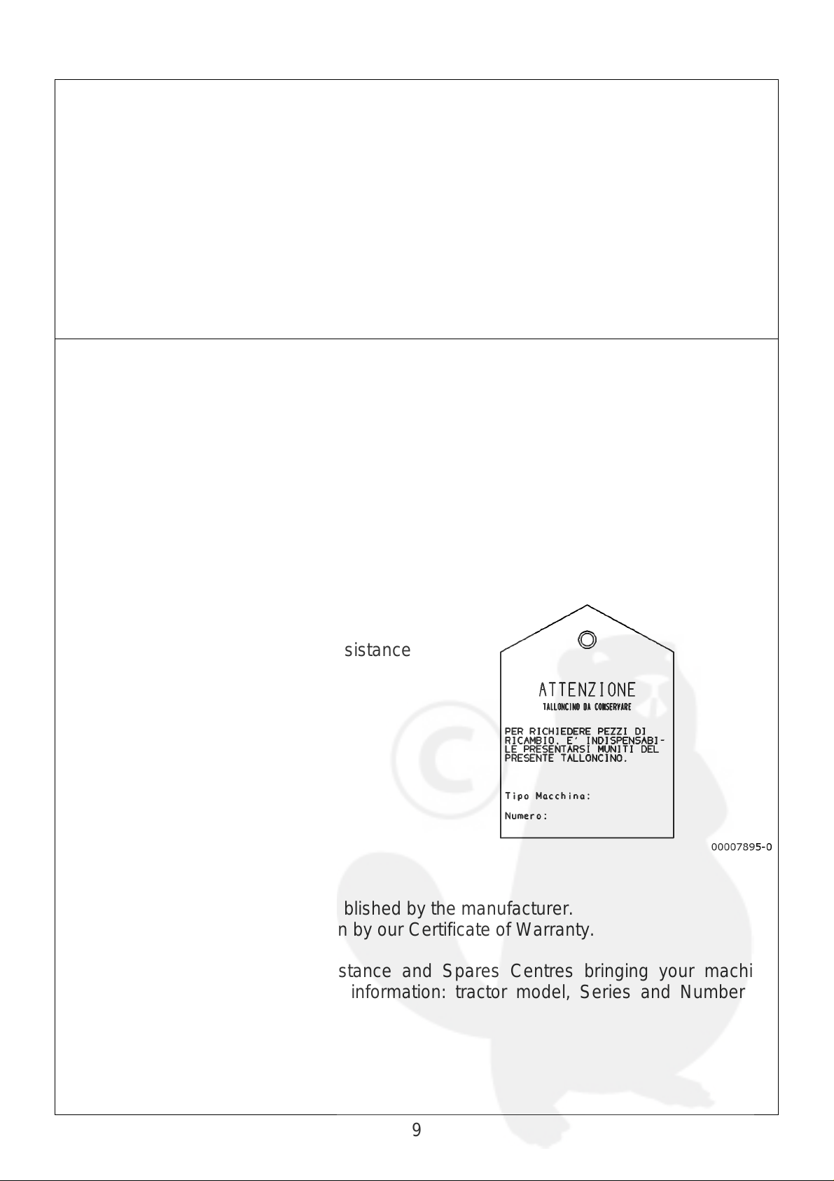
Attention: check to make sure your tractor
has its identification tag. This is essential
when ordering spares from our Assistance
Centres.
Warranty and spares
Engine: conditions and terms established by the manufacturer.
Tractor: within the terms laid down by our Certificate of Warranty.
To order spares: Visit our Assistance and Spares Centres bringing your machine
identification tag or with following information: tractor model, Series and Number as
stamped on the Serial Plate.
9
Page 10
SAFETY
A
How to read the manual
This manual is your operation and maintenance guide. You are
advised to strictly comply with the instructions herein and to
consider the manual as an integral part of the product: it must be
kept near the machine and consigned to all future users.
The illustrations, descriptions and specifications given in this
Manual are not binding on the manufacturer who, while main
taining the main specifications, reserves the right to make any
and all changes, at any time, in compliance with technical or
commercial requirements without prior notice and without
obligation to make such changes to previously manufactured
equipment.
Consult the specific manuals for the safe operation and
maintenance instructions about those parts of the machine
manufactured by third parties.
ll indications as to the “front”, “rear”, “right” and “left” parts of the
machine refer to the operator seated on the machine.
Certain sections of this manual containing information of particular importance in relation
to safety or operation, are highlighted in the following way:
IMPORTANT
The information is given with the intention of preventing damage to the machine
or causing damage.
WARNING
Failure to comply with the instructions could cause personal injuries or harm third
parties.
DANGER
Failure to comply with the instructions could lead to serious danger and serious
personal injuries or harm to third parties.
10
Page 11
Safety regulations
A
There is no substitute for prudence to make your work safer
and to prevent accidents The following cautions are
important for all users of our achines.
Failure to follow the regulations given below exonerates our
firm from all civil and penal responsibility.
Do not tamper with the machine and its equipment in any way.
Before starting the engine make sure that the gear shift and the
PTO are in neutral.
Let out the clutch gradually to prevent the machine from jumping
the clutch.
Do not go downhill with the clutch disengaged or the gear shift in
neutral. Use the engine to brake the machine. If you find you are
using the brake a lot when going downhill, put the machine into a
lower gear.
Follow the traffic code when on-road driving.
o not service, repair or make any kind of adjustment to the tractor
or to equipment coupled to it without having first turned off the
engine, removed the ignition key and lowered the equipment to
the ground.
lways park the tractor so that the utmost in stability is
guaranteed by engaging a gear and applying the parking brake.
On gradients engage 1st gear uphill and reverse downhill. For
greater safety use a chock. Engage front wheel drive if the tractor
has it.
11
Page 12

Check to make sure that all revolving parts on the machines
A
(PTO, Cardan couplings, pulleys etc) are fully guarded. Do not
wear clothing which could be pulled into the machine's or the
equipment's moving parts.
Do not run the engine in an enclosed area: the engine exhaust is
poisonous.
Do not leave the machine with engine running near flammable
substances.
Before driving the machine, check to be sure that there are no
bystanders or animals in its working range.
Do not leave the driving seat with the engine running and/or the
key in the ignition.
Whenever the PTO is in use, the drive shaft must be covered by
the special guard.
From time to time, with the engine shut off, wheel and roll bar
fixing nuts and screws.
fter any maintenance work, grease and remove the grease from
the engine to eliminate the risk of a fire.
12
Page 13
Keep hands and other parts of the body away from holes or leaks
A
in the hydraulic system. The hydrualic fluid from the leak is under
pressure and can cause serious injury.
To not carry any other equipment on the machine apart from that
supplied with it. Do not carry passengers in addition t o the driver.
Do not use the differential lock near or in curves and avoid using
it in fast gears or with engine running at high rpm.
Do not get on or off the machine while it is moving.
void tight steering angles when towed implements are mounted
and the drive shaft is under strain since the coupling could be
damaged.
Do not use the 3-point linkage on the lift as a hitch.
Regulate the hitch in its lowest possible positions to prevent the
machine from rearing.
During transhipments with equipment coupled on the 3-point
linkage, tension the chains and keep the lift raised.
13
Page 14

The operator must check if every part of the tractor and,
especially the safety devices, are in good working condition and
perform to specs. They should be kept in perform working
condition. If you note any defects or malfunctioning, fix or repair
them in good time. If necessary contact your nearest Assistance
Centre. Failure to observe these instructions will release the
manufacturer from all liability.
Safety decals
Safety decals have been affixed to various parts of the machine.
They indicate potential dangers.
The decals must be kept clean and legible. If damaged, they must
be replaced.
Some of the machine components can be equipped with the
manufacturer’s specific safety decals.
14
Page 15
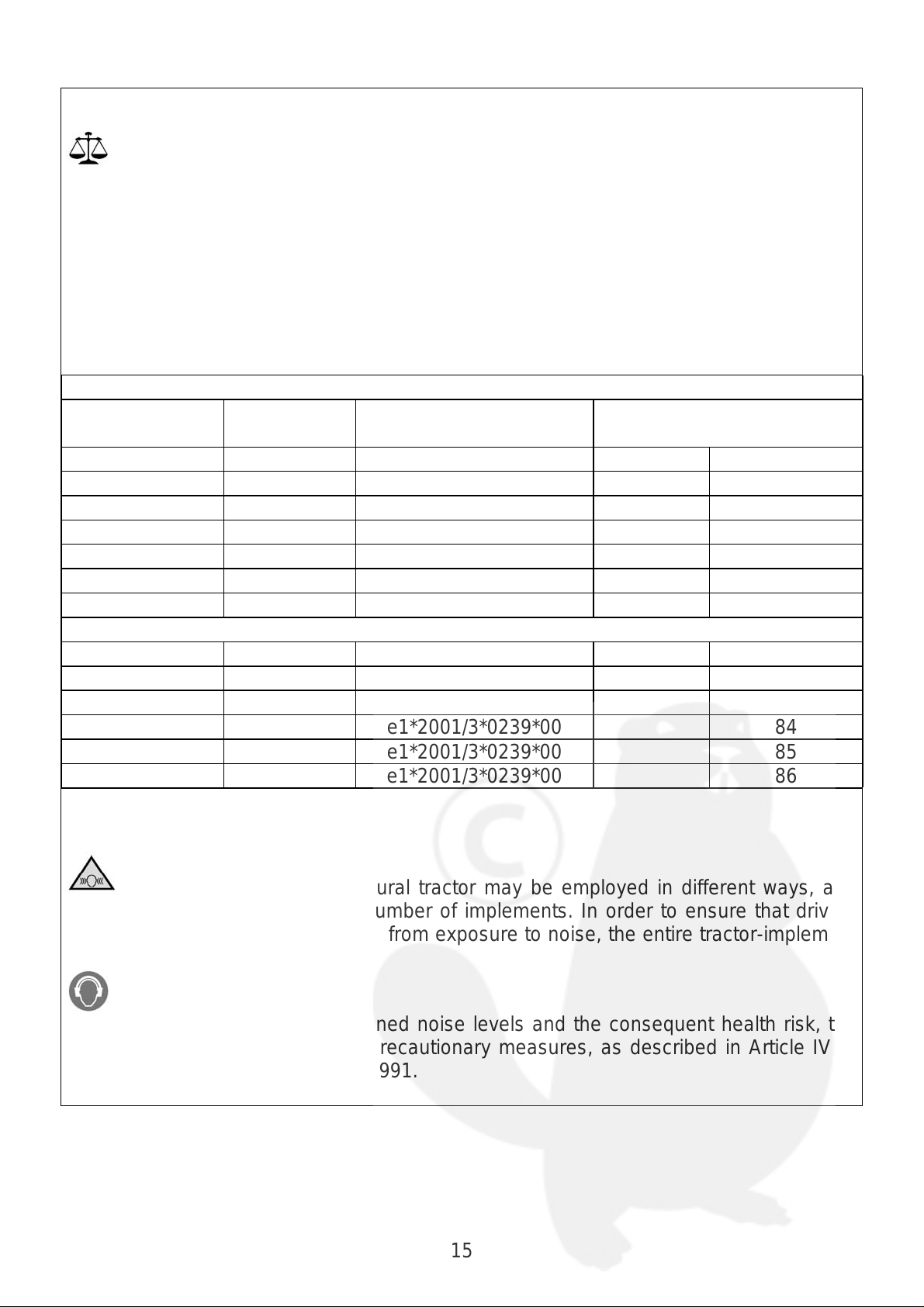
Information about tractor noise levels
This Chart, which provides the noise values produced by the tractors described in
the Guide to Maintenance and Use, has been prepared in order to satisfy the
requirements of Law Decree No. 277 dated 15/08/1991.
Bearing in mind the impossibility of the manufacturer to foresee the normal working
conditions in which the agricultural tractor will be operated, the noise levels have been
defined in accordance with the methods and conditions described in Attachment 8 of
Presidential Decree No. 212 dated 10/02/1981. This conforms to Directive 77/311/CEE
concerning noise levels at the ears of the driver of wheeled agricultural tractors.
TRACTORS with SAFETY BARS
Model Type Type Approval N° Maximum noise level at
the driver’s seat dB (A)
Article I Article II
Aster 35 TX1A -TX1B e1*2001/3*0239*00 83
Aster 40 TX3A -TX3B e1*2001/3*0239*00 83
Aster 45 TX5A e1*2001/3*0239*00 83
Milenio 35C TX1A -TX1B e1*2001/3*0239*00 83
Milenio 40C TX3A -TX3B e1*2001/3*0239*00 83
Milenio 45C TX5A e1*2001/3*0239*00 83
TRACTORS with CAB
Aster 35 TX2A - TX2B e1*2001/3*0239*00 84
Aster 40 TX4A - TX4B e1*2001/3*0239*00 85
Aster 45 TX6A e1*2001/3*0239*00 86
Milenio 35C TX2A - TX2B e1*2001/3*0239*00 84
Milenio 40C TX4A - TX4B e1*2001/3*0239*00 85
Milenio 45C TX6A e1*2001/3*0239*00 86
WARNING TO THE USER
Remember that the agricultural tractor may be employed in different ways, and
may be connected to an infinite number of implements. In order to ensure that drivers
are protected against risks deriving from exposure to noise, the entire tractor-implement
group must be considered.
Bearing in mind the above-mentioned noise levels and the consequent health risk, the
user must adopt the appropriate precautionary measures, as described in Article IV of
Law Decree No. 277 dated 15/08/1991.
15
Page 16
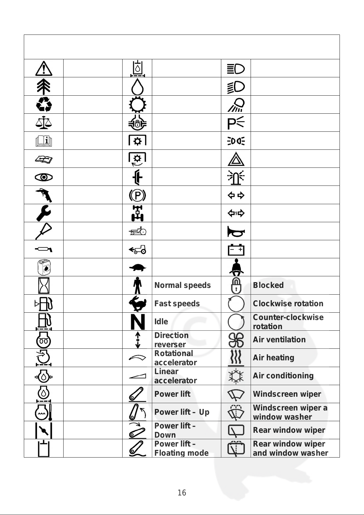
Standard symbols
r
p
p
r
r
r
p
r
r
r
g
r
Standard symbols have been used to ensure the machine is used in the best way.
Warning
Environment Oil Dipped beam
Recycling Transmission Field light
Legislation Differential lock Parking light
Information Power take-off Side lights
Hydraulic circuit
filte
Driving beam
Instructions
Check Clutch Indicator light
Clean with
com
Adjustment Four-wheel drive Trailer turn indicator
Lubrication Guard lowered Horn
Greasing
Change oil Low speeds Safety belts
Work hours Normal speeds Blocked
Fuel level Fast speeds Clockwise rotation
Fuel filter Idle
Engine
Engine air
filte
Engine oil
Engine oil
filte
Engine
coolant
Air valve
Hydraulic
circuit
ressed
reheating
ressure
Power take-off
rotation
Parking brake Turn indicator
Forward
direction
Direction
reverse
Rotational
accelerato
Linear
accelerato
Power lift Windscreen wiper
Power lift – Up
Power lift –
Down
Power lift –
Floatin
mode
Hazard lights
Battery charger
Counter-clockwise
rotation
Air ventilation
Air heating
Air conditioning
Windscreen wiper and
window washe
Rear window wiper
Rear window wiper
and window washe
16
Page 17

Ecology
It is of fundamental importance to safeguard the environment. Incorrect waste disposal
can alter the environment and the ecological system.
Do not discard fluids like fuels, lubricants, coolants or other, in the environment.
Do not use food or dink containers, which could lead to mistakes, to drain off
fluids like fuels, lubricants, coolants or other.
Do not dispose of parts of the cooling system (such as radiators, fluids, tanks,
etc.) in the environment.
Contact an authorized organization or ask your dealer for advice about how to
recycle or dispose of waste products in the correct way.
17
Page 18
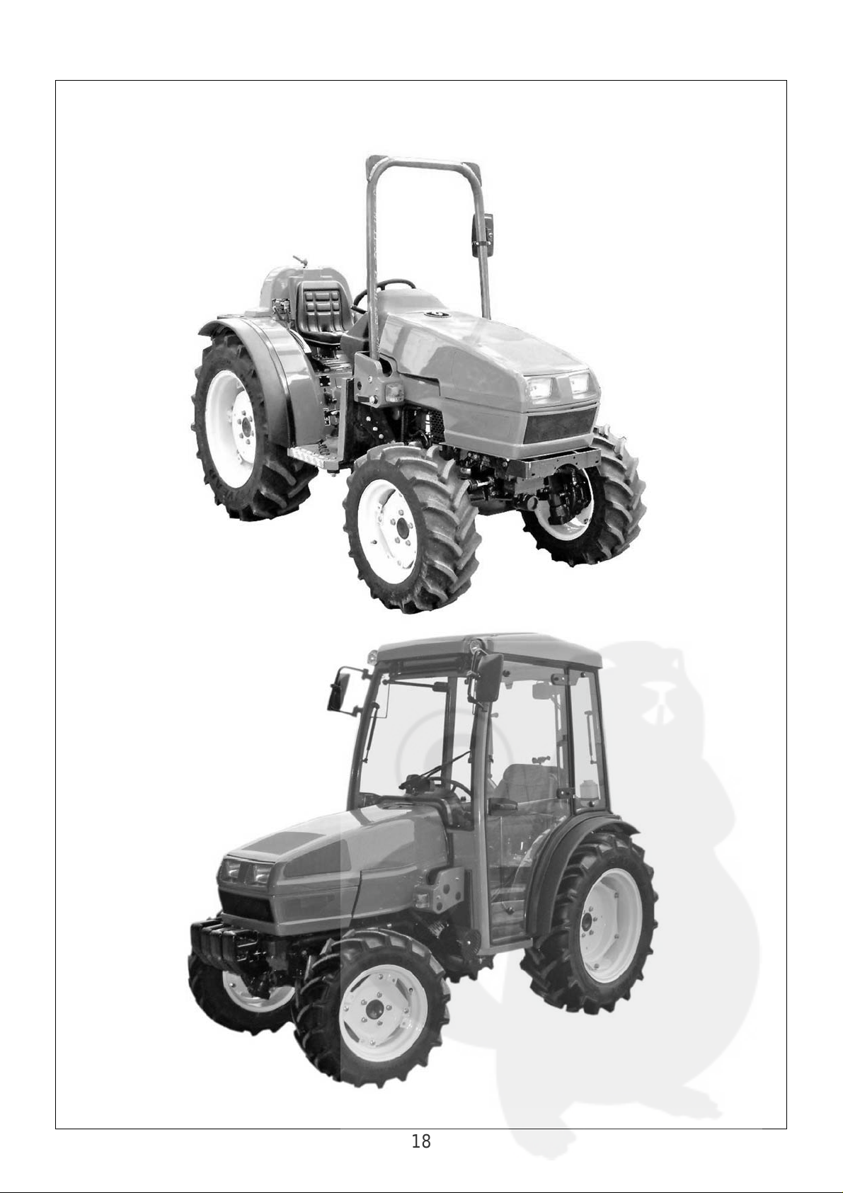
IDENTIFICATION OF THE MACHINE AND COMPONENTS
18
Page 19
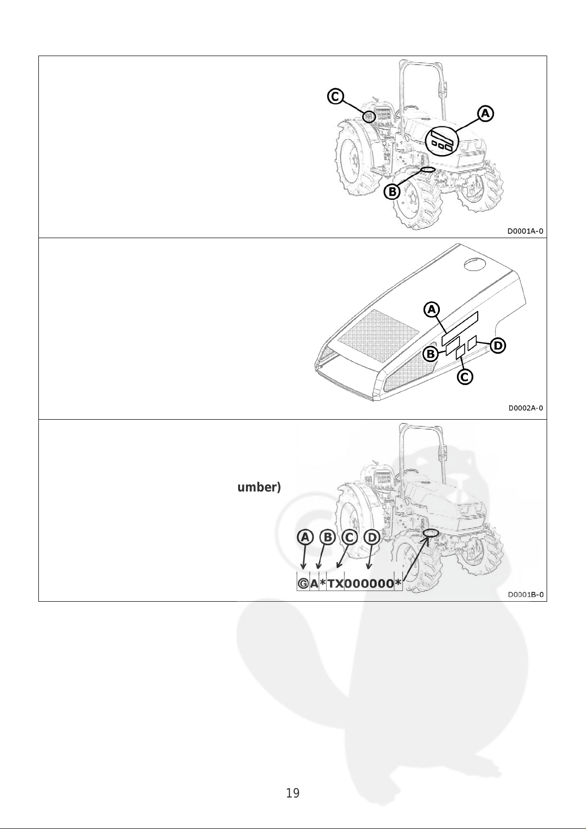
Machine identification
The machine is identified in three different
ways:
A with decals
B punch marks on chassis
C with a metal plate
Decals
The decals affixed to the bonnet indicate:
A Make
B Series
C Model
D Version
Punch marks on chassis
A Manufacturer’s code
B Production series
C Type of machine
D Identification number (serial number)
19
Page 20
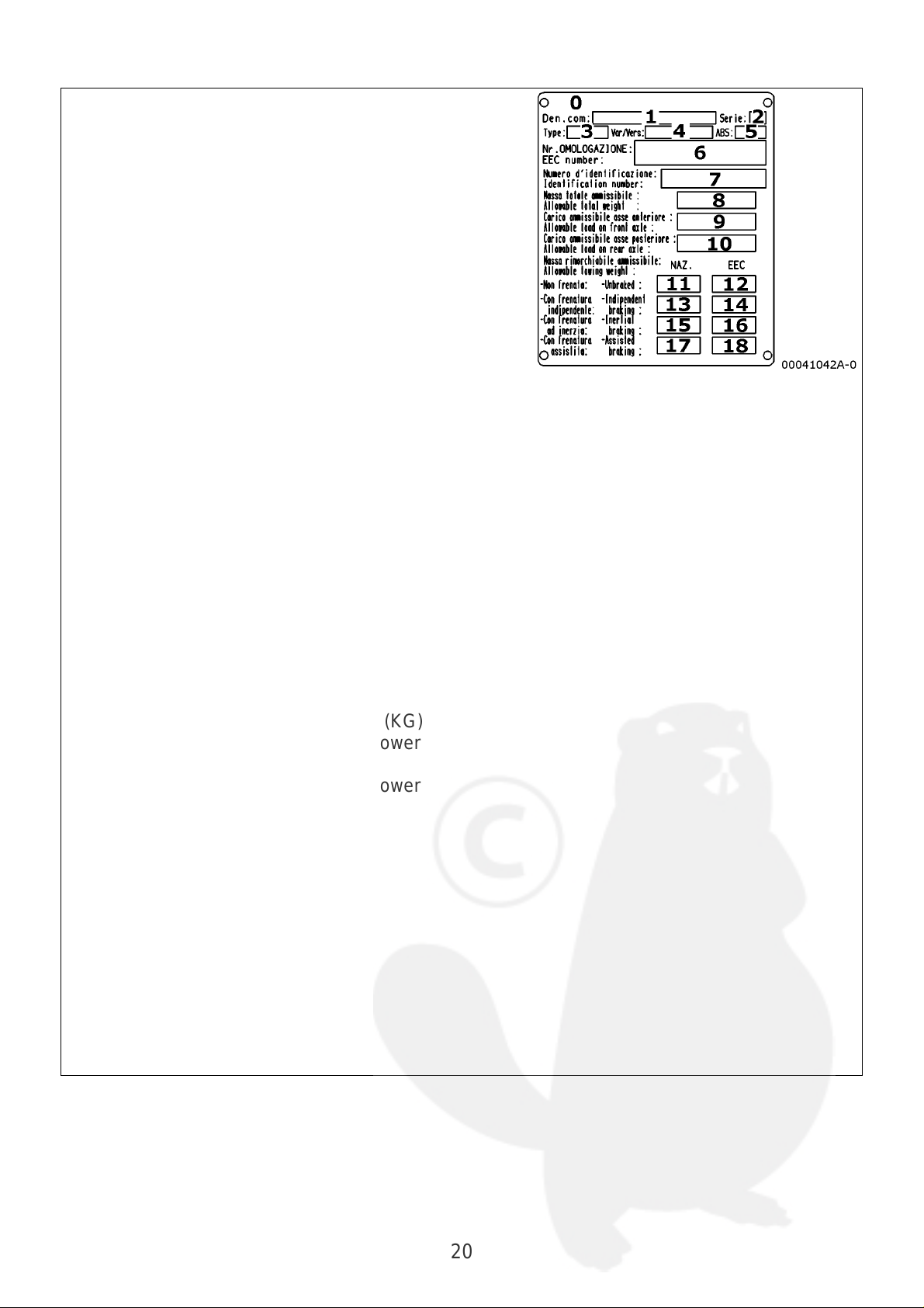
Metal plate
The metal plate gives the following
information:
Manufacturer’s name and address
0
Commercial denomination
1
Production series
2
Type of machine
3
Variant
4
ABC coefficient
5
Approval number
6
Identification number (serial number)
7
Total permissible weight (KG)
8
Permissible load on front axle (KG)
9
Permissible load on rear axle (KG)
10
Non-braked permissible towed weight (in
11
Italy) (KG)
Non-braked permissible towed weight
12
(European) (KG)
Permissible towed weight with
13
independent braking (in Italy) (KG)
Permissible towed weight with
14
independent braking (European) (KG)
Permissible towed weight with
15
overrunning braking (in Italy) (KG)
Permissible towed weight with
16
overrunning braking (European) (KG)
Permissible towed weight with power
17
braking (in Italy) (KG)
Permissible towed weight with power
18
braking (European) (KG)
20
Page 21
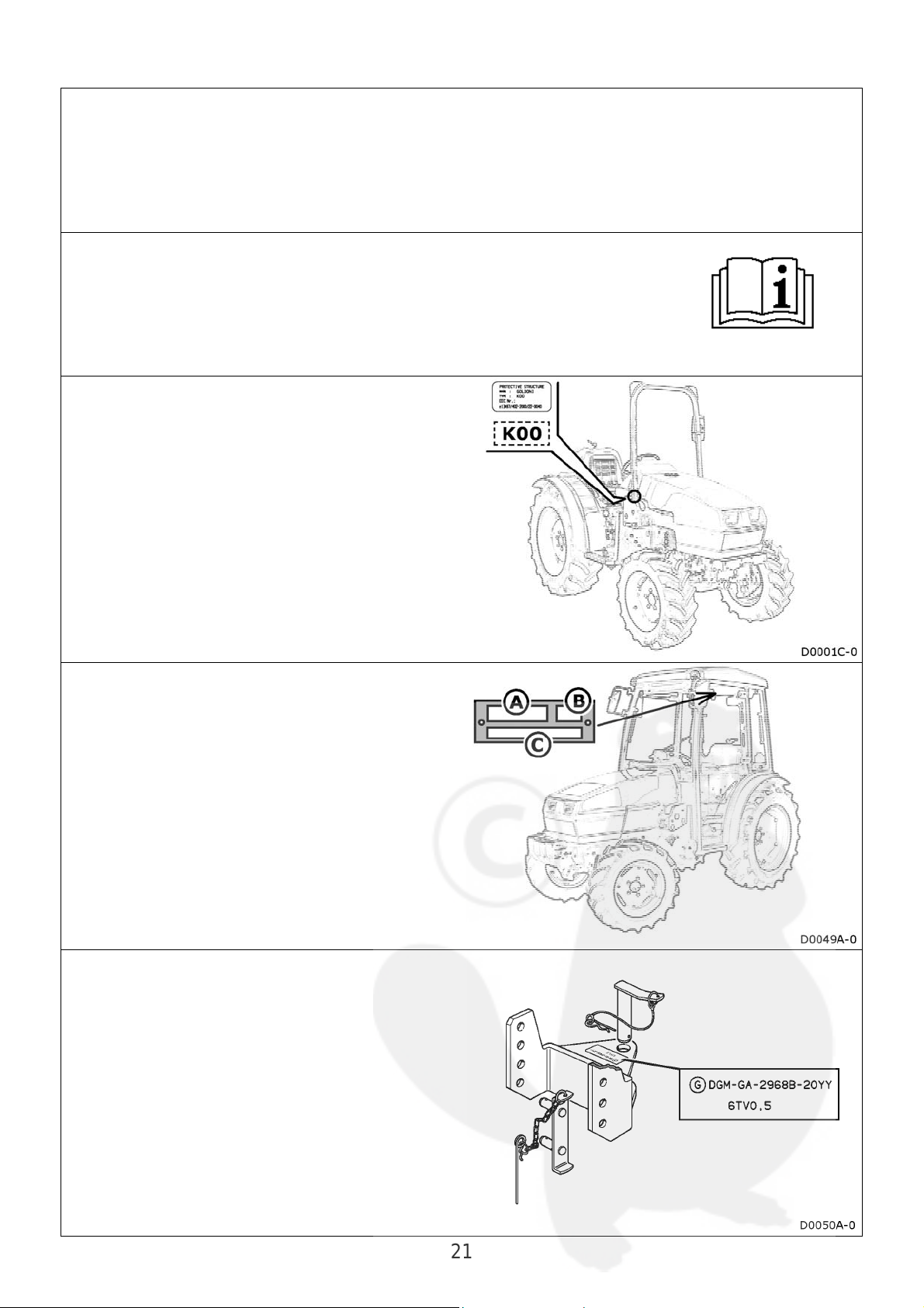
Identification of the components
The machine consists of a series of main components which are
each identified by a metal data plate and/or by punch marks.
Engine
Metal data plate and punched code number.
See engine’s operation and maintenance manual.
Safety frame
• Decal with the Type of safety frame.
• Punched code number on the safety
frame itself.
Cab
Metal data plate on cab:
A Manufacturer
B Type
C Serial number (chassis number)
Towing attachment
Code punched on device:
• Make
• Type of device
21
Page 22
WORK STATION
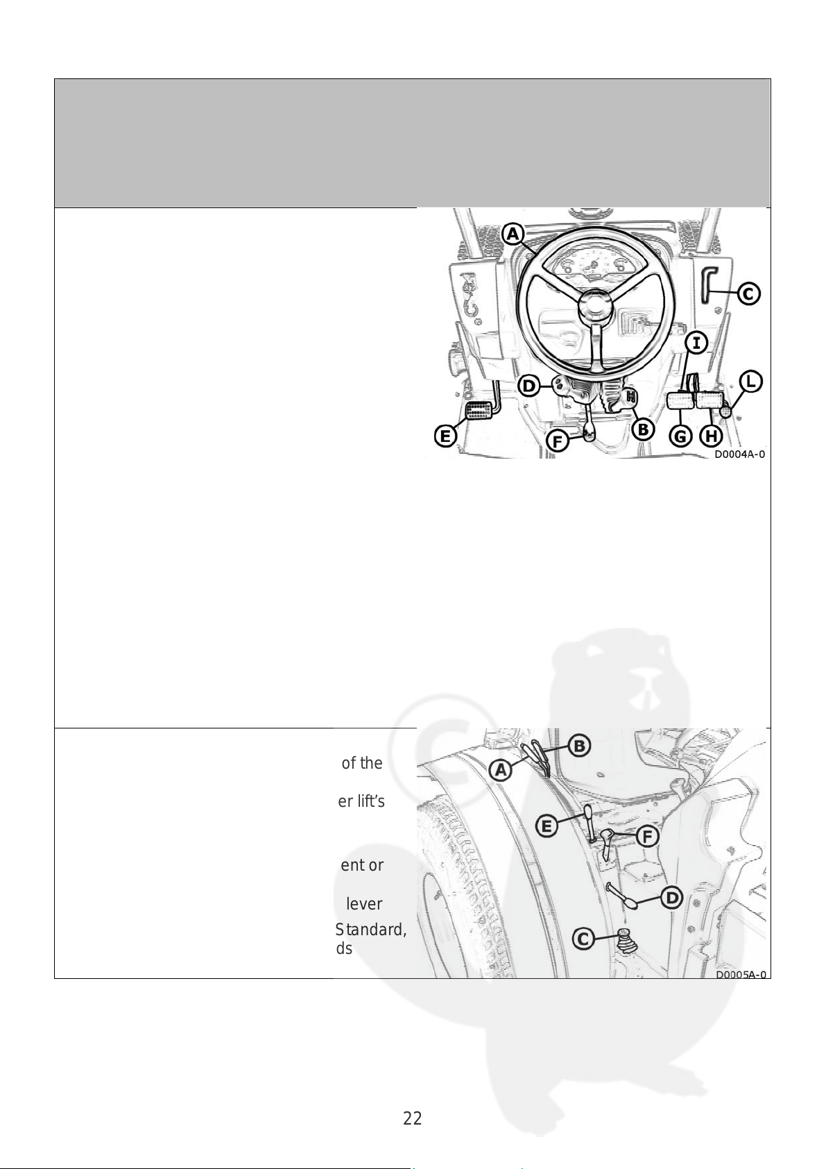
Controls
Controls in front part
A Steering wheel
B Gearshift lever:
speed selection (1-2-N-3-4)
C
Hand throttle
D Reverse shuttle lever:
for selecting forward, reverse speeds
E Clutch pedal
F Rear PTO clutch lever
G LH brake pedal
H RH brake pedal
I Brake pedal latch
L Accelerator pedal
Controls on RH side
Lever for regulating the position of the
A
rear power lift
Lever for adjusting the rear power lift’s
B
draft
Diff lock pedal
C
Lever for selecting the independent or
D
synchronized rear PTO
Rear supplementary spool valve lever
E
Final drive lever: selects Low, Standard,
F
High speeds and Reverse speeds
22
Page 23
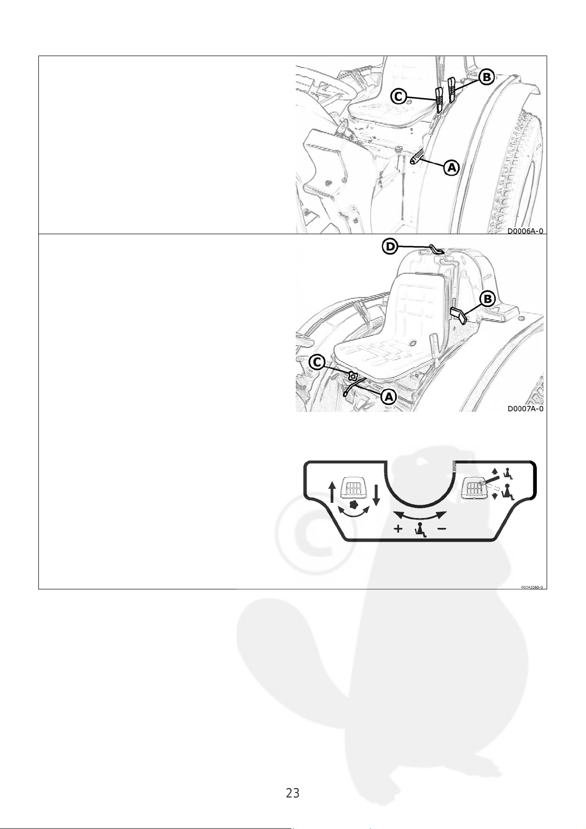
Controls on LH side
A Parking brake lever
B 4 WD lever
C Synchronized rear PTO engaging
lever
Seat controls
A Distance of seat from controls
B Adjustment of seat springs
C Seat height adjustment
D Adjustment of springs
23
Page 24
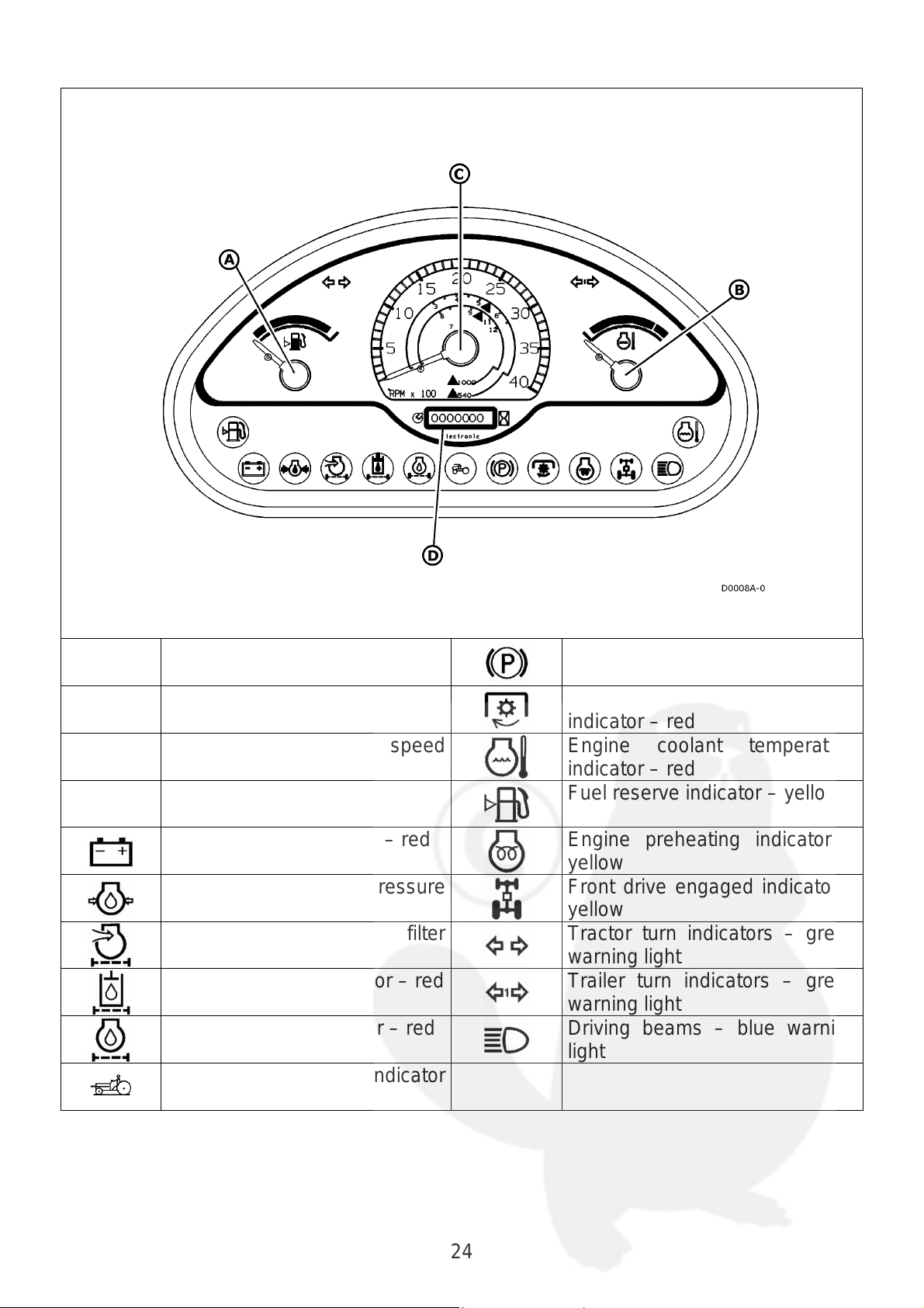
Instruments
Multi-function dashboard
A
B
C
D
Fuel level gauge
Engine coolant temperature
gauge
Engine and PTO speed
indicator
Hour counter
Battery charge indicator – red
Low engine oil pressure
indicator – red
Clogged engine air filter
indicator - red
Clogged oil filter indicator – red
Engine oil level indicator – red
Safety frame lowered indicator
- red
Parking brake engaged
indicator – red
PTO clutch disengaged
indicator – red
Engine coolant temperature
indicator – red
Fuel reserve indicator – yellow
Engine preheating indicator –
yellow
Front drive engaged indicator –
yellow
Tractor turn indicators – green
warning light
Trailer turn indicators – green
warning light
Driving beams – blue warning
light
24
Page 25
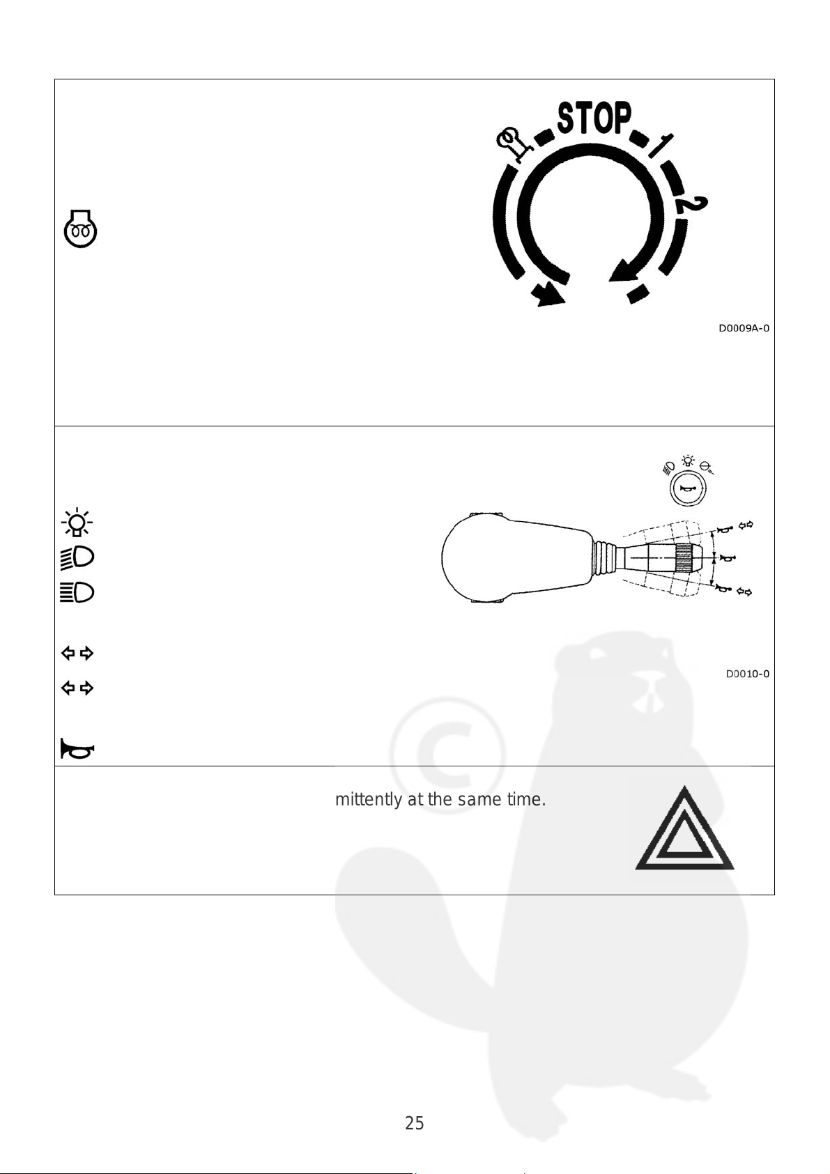
Ignition switch
Engine preheating position
No circuits powered. Key can be
STOP
removed. Turn the key to this position
to switch off the engine.
Operating position. Various users
powered. Indicators and monitoring
1
instruments operative.
Engine starts.
2
Light switch
Light operation:
Lights off
0
Side lights on
Dipped beams
Push: Driving beams
Turn indicator:
Forwards: lh turn indication
Back: rh turn indication
Horn:
Push
Hazard light switch
Flashes all the turn indicators intermittently at the same time.
25
Page 26
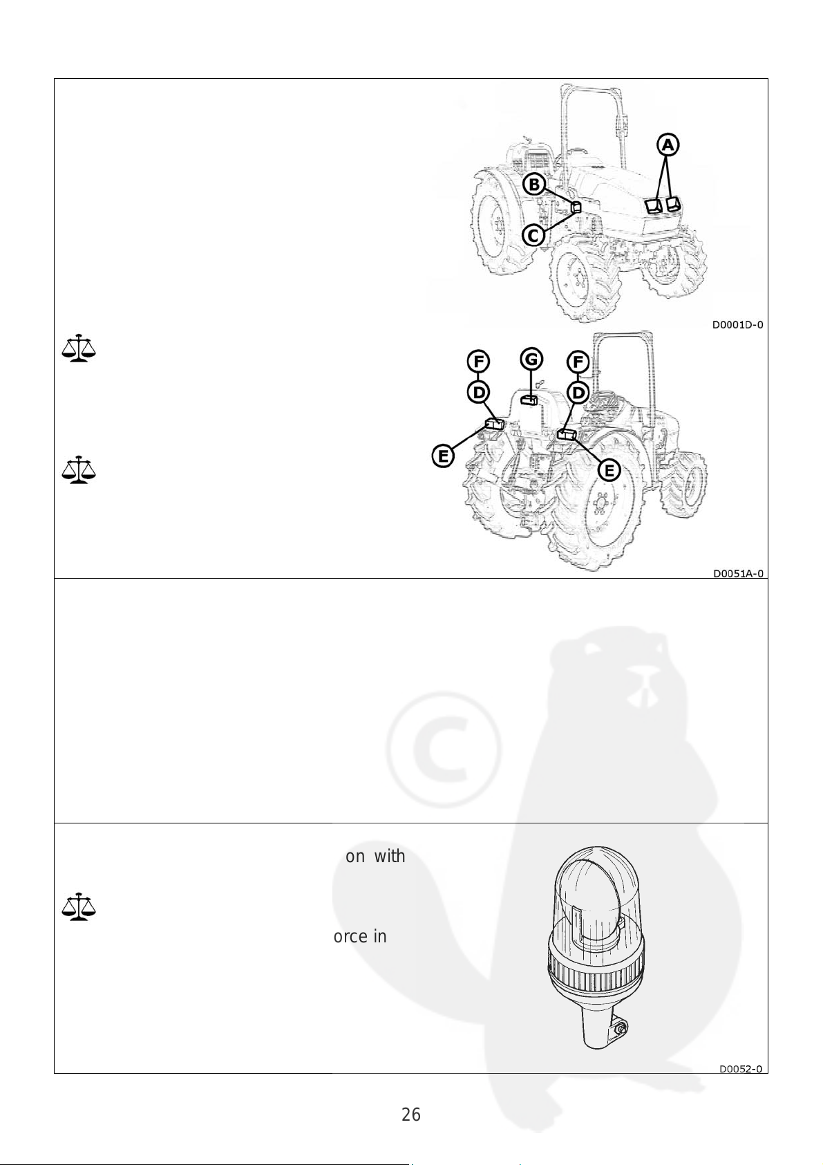
Lights
Headlight in dipped/driving positions
A
Front turn indicator
B
Front side light
C
Rear side light
D
Rear turn indicator
E
Rear brake light
F
License plate light
G
The vehicle’s lights must comply with the
Highway Code in force in the relative
country of use for driving on public
thoroughfares.
Use of driving beams is governed by the
Highway Code in force in the country of
use.
Lights (with cab)
Front field light
Rear field light
Revolving beacon (optional)
The revolving beacon is switched on with
button A
Its use is governed by the laws in force in
the country of use.
26
Page 27

7-pin trailer socket
This socket is used to connect lights, turn
indicators and other electrical devices for a
trailer or implement.
Supplementary lights must be used if an
implement obscures the turn indicators or
other lights at the rear of the machine.
Terminal functions:
A Lh turn indicator
B Vacant
C Ground
D Rh turn indicator
E Rh rear light
F Brake lights
G Lh rear light
27
Page 28

Battery
Symbols:
Protect the eyes
Read the instructions
Keep well out of children’s reach
Dangerous corrosive acid
Avoid naked flames and sparks
Danger of explosion
WARNING: The battery may be equipped with the
manufacturer’s instructions for safe use and maintenance.
Read these instructions and contact specialized personnel if
you have any doubts.
28
Page 29

Safety frame (roll-bar or ROPS)
The machine is equipped with a folding safety frame. Always keep the safety frame
mounted in its correct vertical position when you are working. It is absolutely forbidden to
modify the structural components of this type of construction by welding on additional
parts, drilling holes, grinding, etc. Failure to comply with these recommendations could
impair the rigidity of the frame itself.
The safety frame is subjected to considerable stress if the tractor tips over. If this
happens, the structural components must be replaced if they have been bent, deformed
or damaged in some other way.
When in the horizontal position, the safety frame will provide no protection if the
tractor tips up. When working in these conditions, it is of the utmost importance
for the operator to pay the greatest attention when manoeuvring the machine.
Raise the safety frame again as soon as the machine is able to operate in normal
conditions.
To lower the safety frame, on both sides:
• turn the pin through 90° and remove it
• lower the safety frame
• insert the pin into the second housing
and turn it through 90°
29
Page 30
Cab
A
• Always shut the doors before moving
off with the tractor.
• Keep the windows clean to ensure
good visibility.
• The cab is approved as a safety
structure. It is therefore absolutely
forbidden to tamper with it, modify or
add extra equipment and/or
supports.
Versions
The machine can be equipped with a cab in
three different versions:
• Cab without ventilation (Basic version)
• Cab with heating function (Top Calda)
• Cab with heating and air conditioning
(Top Fredda)
ccessories: activated carbon filter and
revolving beacon.
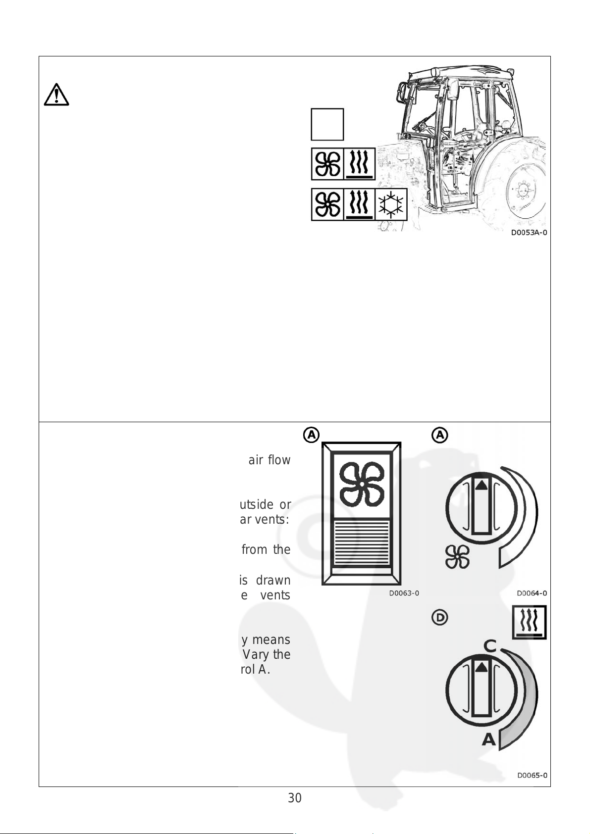
Heating and ventilating
The ventilation function is operated by
means of the control A. Direct the air flow
by positioning front vents.
The air can be drawn from the outside or
from inside the cab by means of rear vents:
• vents closed: the air is drawn from the
outside through the filter.
• vents open: most of the air is drawn
from the inside through the vents
themselves.
The heating function is operated by means
of control D (a =open; c = closed). Vary the
ventilation speed by means of control A.
30
Page 31

Air conditioning
A
The air conditioning system allows you to
obtain fresh, dehumidified air or hot
dehumidified air.
• Never tamper with the air
conditioning system: always contact
specialized personnel.
• Keep naked flames and heat
sources well away from the air
conditioning system.
• Never loosen unions and/or
tamper with pipes: the system is
pressurized.
• The refrigerant can freeze the skin
and eyes.
Starting and stopping the engine
Make sure that the air conditioner and fan
are off before starting the engine.
lways turn off the air conditioner and fan
before stopping the engine.
Operation
To operate the air conditioning system:
1) stop the heating function by means of
knob C (set to position C)
2) use knob A to turn on the ventilation
3) use knob L to turn on the cooling
function.
If the fan on the cab roof fails to start within
one minute once the system has been
turned on, turn it off and check the fuses.
Failure of the rear fan to operate will raise
the pressure of the gas in the air
conditioner’s circuit and could block the
system.
Technical specifications:
Refrigerant fluid: R134a
Quantity: 0.8 kg
31
Page 32

Cab air filter
Warning: the cab air filter has not
been designed to retain harmful
substances! Comply with the
instructions provided by the
manufacturer of the substance used.
The air that enters the cab is always
subjected to a filtering treatment. The filter
is installed in the top front part of the cab.
Cab air filter with activated carbon (optional)
Comply with the use and maintenance instructions supplied with
the filter.
Warning: use of the cab air filter with activated carbon
does not relieve the operators from wearing recommended
personal protective equipment to safeguard against the
harmfulness of the individual substances used.
Switches
The cab switches are installed in the ceiling
of the cab itself, on the right-hand side.
They are used for the following functions
(some of which are optional):
1- 0
Front field lights
Front and rear window wipers and
washers.
Revolving beacon
Rear field lights
- Ceiling light
Rear window wiper
Accessories
Sun shade
Installed on the front window. To unwind, pull on the handgrip situated in the center of
the shade; to rewind, use the red button on the right-hand side of the winder.
Pre-engineering for stereo system
Installed in the rear cab interior. Includes 2 housings for loudspeakers
Document pocket
32
Page 33

Cab and safety frame approval
(Optional)
- For Italy
If the cab and roll bar are installed after the purchase of the tractor, the customer should
ask our Sales Division for the corresponding Approval documents.
With these documents and the registration book and/or Log Book, the customer should
go to his local Ministry of Transport Licencing Office. This office will update or replace
the registration book/Log Book.
- For other countries
If the cab or roll bar are installed after the purchase of the tractor, the owner should refer
to the national approval agencies to have the tractor's registration or log book brought
up to date.
Safety belts (where applicable)
Wear the safety belts when you use the
machine with the safety frame (roll-bar or
ROPS) to reduce the risk of accidents if the
tractor tips up.
Do not wear the seat belt if you use the
machine with the roll-bar in the
horizontal position.
Tool box
The machine has a tool box which can be
accessed by turning the knob.
33
Page 34

OPERATING INSTRUCTIONS
How to start and stop the machine
How to start the engine
Consult the engine’s operation and maintenance manual.
Before starting the engine:
Apply the parking brake
Move the final drive lever to the neutral position
Move the lever used to select the independent or synchronized rear PTO to
the neutral position.
Move the lever used to select the PTO speed to the neutral position
Move the hand throttle lever halfway along its travel
Depress the clutch pedal
Ignition switch:
Insert the key and turn it as described
below:
Glow plug preheating. Keep the key
in this position for 8-10 seconds.
STOP
No circuit powered
Instruments and warning lights on
1
(operating position).
Engine starts.
2
After the engine has started:
• Release the key. It will automatically return to the operating position.
• Release the clutch pedal.
• Check the warning lights and instruments.
34
Page 35
How to start the machine
Before starting the machine, make sure you become familiar with its main
controls: brakes, transmission, PTO, diff lock and how to stop the engine.
Make sure that the brakes are efficient before moving off.
• Depress the clutch pedal.
• Select the transmission ratio (consult the Gearbox chapter).
• Disengage the parking brake.
• Gradually release the clutch pedal.
• Gradually accelerate the engine.
How to stop the machine
• Allow the engine to idle.
• Depress the clutch pedal.
• Stop the machine
• Move the final drive lever to the idle position.
• Apply the parking brake.
How to stop the engine
• Turn the ignition key to position 0.
• Remove the key and put it away in a safe place.
WARNING: The steering action of the power steering system will be reduced if the
engine accidentally stops. Depress the main brake to allow the machine to come to a full
stop.
35
Page 36

How to move off
Main clutch
Transmits drive from the engine to the transmission.
Pedal up = clutch engaged (drive is transmitted)
Pedal down = clutch disengaged (drive not transmitted)
Make gradual engagements and disengagements.
Remove your foot from the clutch pedal when not required.
lengthy clutch disengagements could wear out the thrust bearing.
NEVER attempt to drive up or down slopes with the clutch disengaged.
Gearbox
The machine’s transmission comprises a gearbox, final drive and synchronized reverse
shuttle, each controlled by its own lever.
The speed at which you drive the machine must be chosen to suit:
• the work required
• the implement used
• the type of ground
Information about the ground speeds is given in the “technical specifications” section.
Gearshift lever
(1-2-N-3-4)
The lever can be moved in four positions
(plus neutral):
1 = first speed gear
2 = second speed gear
N = neutral
3 = third speed gear
4 = fourth speed gear
The speed gear selections are
synchronized.
To change gear:
• disengage the main clutch
• select the required position.
36
Page 37

Final drive lever
The lever can be moved in four positions (plus neutral):
Standard speeds (Man)
Low speeds (Tortoise)
High speeds (Hare)
Reverse speeds (REV)
Selection is not synchronized.
To select the required range:
• stop the machine
• disengage the main clutch
• select the required range
Reverse shuttle lever
The lever has two positions (plus neutral):
forward
reverse
Selection is synchronized.
Even though selection is synchronized,
proceed as described below to select the
forward or reverse speeds:
• stop the machine
• disengage the main clutch
• select the forward or reverse speed.
37
Page 38
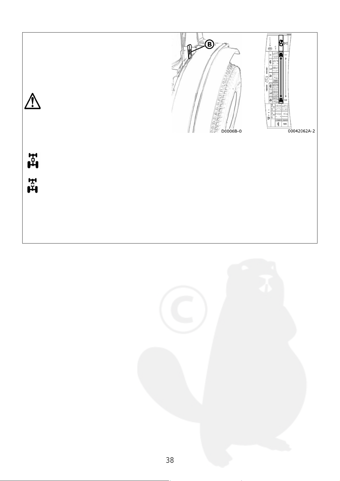
Four wheel drive
A
The tractor is the four wheel drive type
(front and rear). Four wheel drive is
recommended for ploughing jobs or if one
of the two driving wheels possess
insufficient grip owing to muddy, rugged or
slippery ground.
Do not use four wheel drive on roads as
the tyres will quickly wear out.
The four wheel drive is engaged
mechanically with lever B:
four wheel drive engaged
four wheel drive disengaged
n indicator light will come on to show that
four wheel drive has been engaged.
38
Page 39

Rear diff lock
The tractor is equipped with a rear diff lock which should be used
for ploughing work or if one of the two driving wheels possesses
insufficient grip owing to muddy, rugged or slippery ground.
The diff lock is controlled mechanically with pedal C. It is
disengaged by releasing the pedal.
To get the most out of the device, engage the differential lock
before the wheels begin to slip. Do not engage the lock while one
wheel is already slipping.
Only use the diff lock with the low and standard speed gears
and after having previously slowed the engine rate.
Do not use the diff lock near or round bends.
If the diff lock fails to release, reduce the engine rate, stop
the machine and release it by moving the steering wheel.
Power take-off
Rear power take-off (PTO)
The tractor has two shafts for the rear
power take-off (PTO):
• INDEPENDENT power take-off
• SYNCHRONIZED power take-off
Do not remove or damage protective
plate A
Cover the PTO shaft with guard B when
not used.
39
Page 40

INDEPENDENT power take-off
• Rotation directly connected to the engine.
• Upper shaft.
• Consult the technical specifications section for further details.
The independent PTO is selected
mechanically with lever D
The PTO is engaged mechanically by
pulling guard A and raising clutch lever B.
The PTO is disengaged by pulling guard A
and lowering lever B.
40
Page 41

SYNCHRONIZED power take-off
• Rotation proportional to the tractor’s ground speed
• Lower shaft
• Consult the technical specifications section for further details.
The synchronized PTO is selected
mechanically by moving lever C to the
position with symbol 1
The synchronized PTO is disengaged by
means of clutch pedal E
41
Page 42
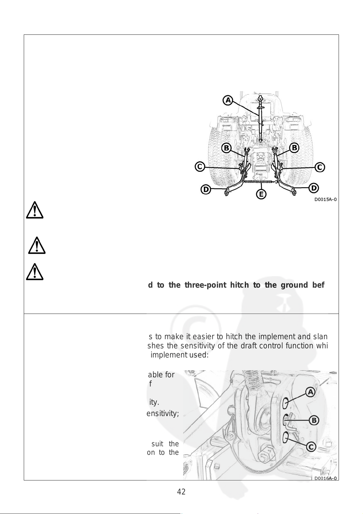
Three-point hitch
A
The tractor is equipped with a three-point hitch. To ensure that this system operates
correctly, make sure that the size and weight of the implement used correspond to the
specifications of the power lift and hitch itself.
Consult the technical specifications section for further details.
Components:
A Third point link
B Adjustable rod (pair)
C Side stabilizer (pair)
D Power lift’s lower link (pair)
E Spring
ALWAYS switch off the engine before hitching or adjusting the three-point hitch in
any way.
The third point coupling must NOT be used for towing implem ents.
Lower the implement connected to the three-point hitch to the ground before
getting off the tractor.
Third point link
Coupling
The third point coupling has 3 holes to make it easier to hitch the implement and slant it
at the correct angle. It also establishes the sensitivity of the draft control function which
must be selected to suit the type of implement used:
A
Top hole: less sensitivity; suitable for
implements that create a lot of
tractive effort.
B Central hole: medium sensitivity.
C
Bottom hole: greater sensitivity;
suitable for light implements.
Adjustment
djust the length of the link to suit the
implement’s coupling angle in relation to the
ground.
42
Page 43

Adjustable rod (pair)
The rod can be adjusted so as to level and
align the lower links to suit the implement used
and the type of work required.
Side stabilizer (pair)
The stabilizers must be adjusted to limit the
side swing of the power lift’s lower links:
5-6 cm swing
for ploughs, rotary harrows, etc.
Min. swing
for leveling blades, hoeing attachments,
etc.
0 swing
for transporting implements that are not
working.
Universal joint
Consult the specific manual for the safe operation and
maintenance instructions concerning certain parts of the machine
manufactured by third parties.
43
Page 44

Rear power lift
The following operating conditions can be applied:
• Controlled position
• Controlled draught
• Floating mode
• Combined mode
Controlled position
Ideal for jobs that required constant
implement position (drills, scraper, hitched
manure spreader, etc.).
• Move lever B fully forwards.
• Use lever A, to raise and lower the lift.
Lift raising is proportionate to lever
movement.
Draft control
This is used to keep the lugging power the
tractor must provide constantly under
control without overloading the engine and
keeping slippage within very low limits
(ploughs, cultivators, etc.).
• Move lever A fully forwards.
• Use lever B to adjust the required
amount of draft.
• Use lever A to raise and lower the power
lift.
Floating mode
Ideal when you want to leave the
implement free to follow the contour of the
ground (cultivators, ridgers, scrapers, etc.).
• Move lever B all the way back.
• Use lever A to raise and lower the lift.
44
Page 45
Mixed draft and position mode
adjustment
This operating mode is ideal for jobs
carried out in draft control mode on
irregular ground when the implement is
liable to dig too deeply into the soil.
Dig the implement into the ground down to
the desired depth as described for the draft
control mode.
Once the required depth has been
reached, gradually move lever A back
towards the end of travel point until the lift
links begin to slightly raise.
The power lift will operate in the draft
control mode but will stop the implement
from digging too deeply into the soil if it
encounters softer ground. This prevents
the tillage work from becoming irregular.
Only use lever A to raise and dig in the
implement.
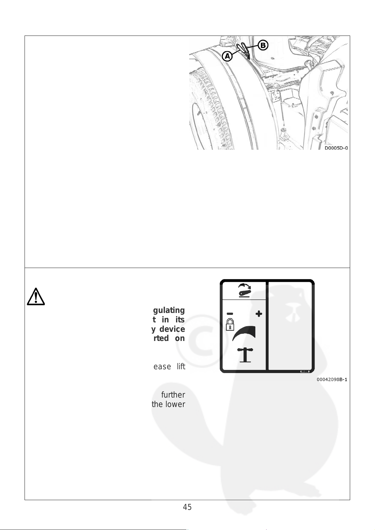
Regulating lift rate and sensitivity
Slacken off completely regulating
screw, to lock the implement in its
raised position. This is a safety device
when implements are transported on
road.
Screw out this regulator to increase lift
lowering speed.
3-point hitch sensitivity can be further
increases by attaching it to one of the lower
tractor hitch holes.
45
Page 46
Towing attachments (optional)
Choose the towing attachment to suit the type of trailer or implement towed, in
compliance with the current laws in force.
Ease of driving the tractor also depends on correct use and height adjustment of the
towing attachment.
WARNING: The tractor could tip up if the towing attachment is set in the highest
position.
Keep the drawbar as horizontal as possible when four-wheel drive is used.
Front tow hook (optional)
The tractor can be equipped with a front
tow hook for emergency manoeuvres with
the trailer or for towing the actual tractor
itself.
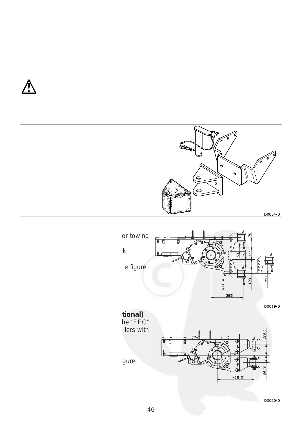
“Category B” tow hook (optional)
The tractor can be equipped with a rear tow
hook of the “CUNA CAT. B” type for towing
trailers with one or two axles.
To adjust the height of the tow hook:
• remove the pins
• position the hook as shown in the figure
• fix the pins in place
“EEC Category” tow hook (optional)
The tractor can be equipped with the “EEC”
type of rear tow hook for towing trailers with
one or two axles.
To adjust the height of the hook:
• remove the pins
• position the hook as shown in figure
• fix the pins in place
46
Page 47
Ballast (optional)
If very heavy implements are hitched to the tractor, the longitudinal stability of this latter
may be impaired. This can be corrected by using one of the various types of ballast
available as optionals.
WARNING: when you determine the type of ballast to use, make sure that you do not
exceed the following limits between the implement and the ballast itself:
• the permissible load on the front axle (KG)
• the permissible load on the rear axle (KG)
The values are given on the tractor’s metal data plate.
Front ballast (optional)
The front ballast consists of cast iron
plates.
The plates have handles so that they can
be assembled and disassembled.
The ballast is fixed in place with blade A
connected with screw B, which must be
tightened to a 5 Kgm (49 Nm) torque value.
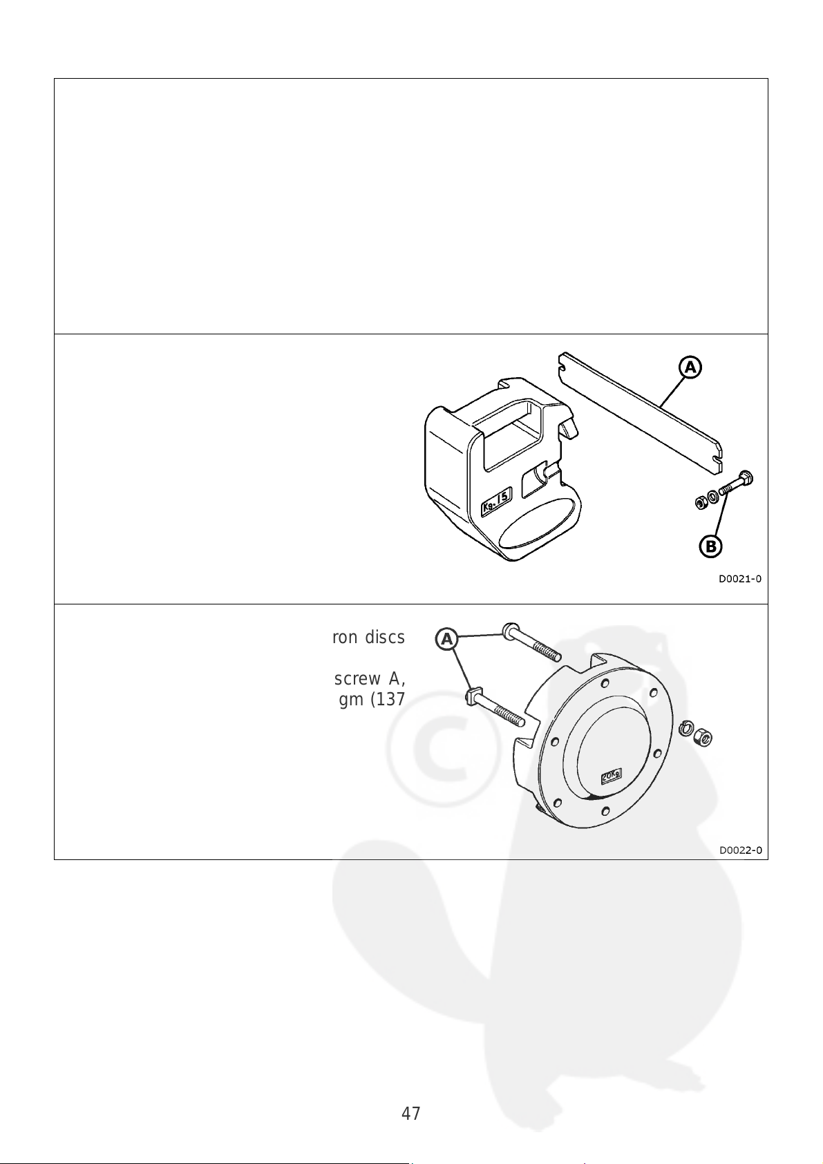
Rear ballast (optional)
The rear ballast consists of cast iron discs
fixed to the wheels.
The ballast is fixed in place with screw A,
which must be tightened to a 14 Kgm (137
Nm) torque value.
47
Page 48

Wheel ballasting by filling the tyres with fluid.
The driving wheels are ballasted by pouring water into the tyres.
Note: it is preferable to use tyres with inner tubes.
Note: if tubeless tyres are used, ask your dealer how to lub ricate the disc correctly so as
to prevent it from rusting.
Note: use water with an antifreeze solution in cold weather (manufacturers recommend
neutral calcium chloride -CaCl
How to pour in the water:
• position the valve at the top
• unscrew the mobile valve union
• pour in the water with a common water
hose
• stop filling every so often, so as to allow
the air to escape
• stop filling altogether when water spills
from the valve.
• the water should fill 75% of the tyre.
• tighten the mobile valve union.
• inflate the tyre to the normal operating
pressure.
How to drain out the water:
• position the valve at the bottom.
• unscrew the mobile valve union.
• allow the water to drain out.
• finish emptying the tyre by means of a
union with a pipe (draw pipe).
• inflate the tyre with air until all the water
has been drained out.
• tighten the mobile valve union.
• inflate the tyre to the normal operating
pressure.
-).
2
48
Page 49

Wheels
Steering angle
The front wheels may interfere with the
body of the machine when the track width
is changed.
To prevent contact, the maximum steering
angle can be regulated with the two limiters
on the front axle:
• raise the front axle by jacking up the
wheels.
• unscrew the two check nuts A.
• work on the two screws B.
• adjust the steering angle by taking the
axle swing into account.
• tighten the two check nuts A.
Note: the steering angle must be the same
on both sides.
Front wheel toe-in
Measure the distance from wheel disc to
wheel disc on the front and rear sides on a
level with the front axle. Distance A must
differ no more than 1.5 mm from distance
B.
Proceed as described below to adjust the
toe-in:
• loosen nut B.
• unscrew or tighten threaded bar A.
• tighten screw B (M18x1.5) with a 34
Kgm (334 Nm) driving torque.
49
Page 50

Track widths
A
The tractor can be equipped with adjustable, reversible wheel discs that allow the track
width to be changed.
Whenever the wheels are reversed, check to make sure that the arrows indicating the
turning direction on the tyre are pointing in the correct direction.
The overall width of the tractor is governed by laws when the tractor is driven on the
roads: comply with the laws in force in the country of use.
WARNING: When disassembling the tyres:
• Take the greatest care
• Use tools and equipment that set the tractor in safe conditions
• Use tools to lift heavy wheels.
Wheel bolt torque values
A The driving torque to fix the flange to the
disc is:
ø 12” = 10Kgm (98Nm)
ø 15”/16” = 15Kgm (147Nm)
ø 18”/20”/24” = 25Kgm (245Nm)
B The driving torque to fix the wheel disc to
the hub is:
Front (M14X1.5) = 15Kgm (147Nm)
Rear (M16X1.5) = 22Kgm (215Nm)
Transmission ratio
The ratio between the tip speed of the front
and rear wheels must be accurately
determined so that the front wheels are in
advance. failing this, the tyres will be
subjected to excessive wear.
sk your dealer for advice when you
change the size of tyres.
50
Page 51

Tyres
Absolutely avoid:
• improper use
• overloading (even localized)
• unsuitable pressures
• unsuitable rim and tyre matches
Tyre life and performance depends on use of the correct operating pressure: if the
pressure is too low, the tyre will quickly wear out while an excessive pressure will reduce
the lugging power and make the wheels more liable to slip.
A correct tyre pressure depends on various factors:
• the operating conditions
• the tractor load
• the tractor model
• the tyre make
• the tyre size
You are therefore advised to consult your dealer or the tyre manufacturer.
The values given below are only approximate as they depend on the conditions
described above:
FRONT: REAR:
2.4 bar 1.6 bar
WARNING: the tyres must only be changed by competent persons in possession
of the necessary equipment and technical know-how.
How to tow the tractor
Only use normal towing attachments (tow bar or hook) for towing both the tractors
(towing and towed).
Only use a safe, strong chain or special rope to connect the two tractors together.
NOTE:
• The tractor must only be towed for short distances and never on the public highways.
• Never drive faster than 10 kph when towing.
• An operator must remain seated in the towed tractor.
51
Page 52

Transporting the tractor
The best way to move a tractor that has broken down is to transport it on the platform of
a truck or trailer.
Fix the tractor to the platform by means of the couplings on this latter and using the tow
hook (front and rear) as a connection point.
Do not fix the chains to the drive shaft, steering cylinders or other components that could
be damaged by the chains themselves.
52
Page 53
MAINTENANCE
Warning! Check the levels:
• Before using the machine
• With the machine at a standstill and the engine off (for at least the past hour).
• On a flat surface.
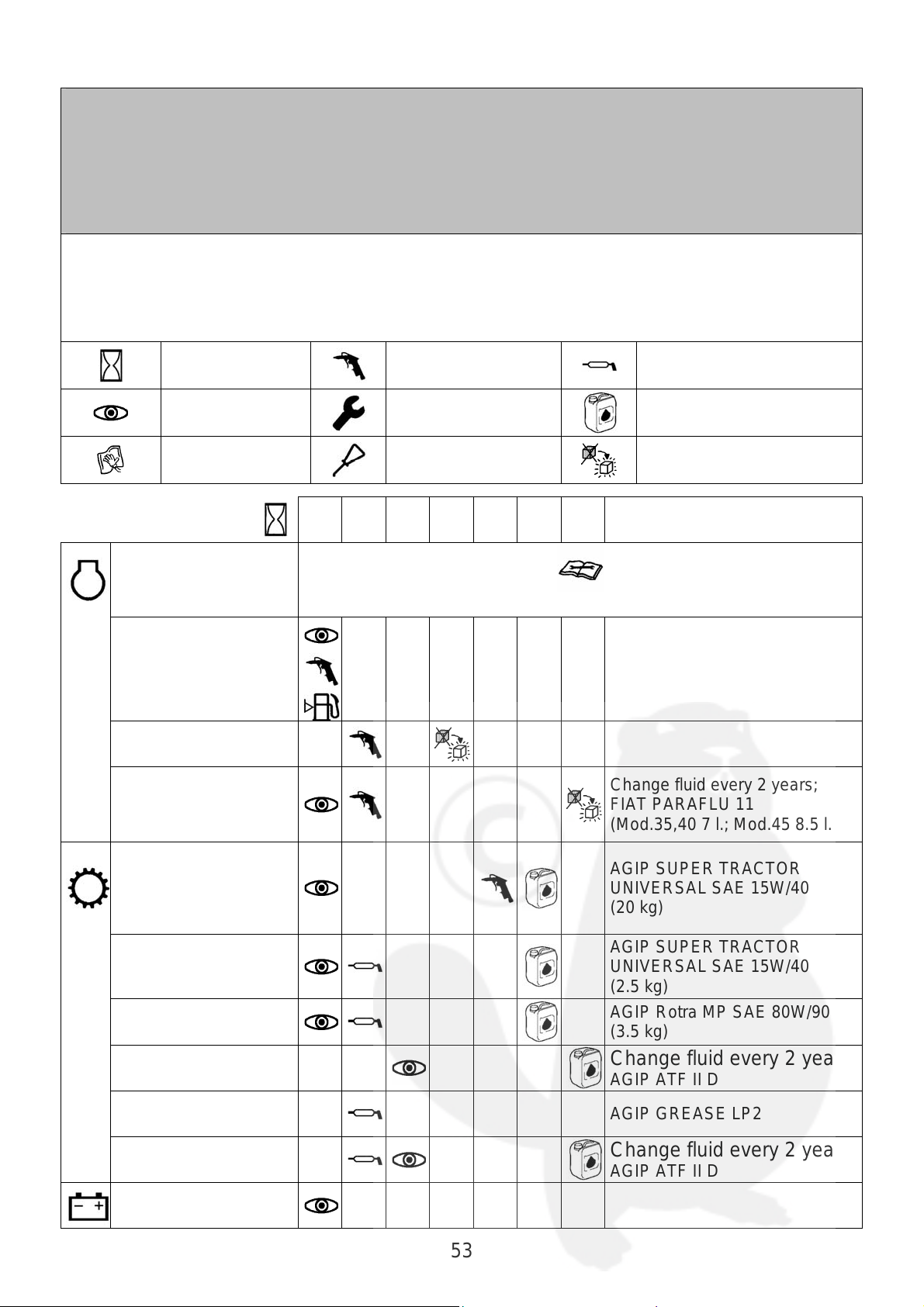
Routine maintenance guide:
This table briefly outlines the routine maintenance jobs. Consult the following pages for
more details about routine maintenance or information about the variable servicing work
required.
Hours of
service
Cleaning with
compressed air
Greasing
Check
Clean
8 50 150 300 400 800 x
Adjust
Lubricate
Engine
Consult the engine’s operation and maintenance manual
Change oil
Replace
Notes:
Fuel tank
Dry air filter
Cooling circuit
Change fluid every 2 years;
FIAT PARAFLU 11
(Mod.35,40 7 l.; Mod.45 8.5 l.)
Gearbox housing,
rear differential,
power lift
Front axle
mod.35-40
Front axle
mod.45
Rear diff lock
Final drive lever
Brakes
Battery
53
AGIP SUPER TRACTOR
UNIVERSAL SAE 15W/40
(20 kg)
AGIP SUPER TRACTOR
UNIVERSAL SAE 15W/40
(2.5 kg)
AGIP Rotra MP SAE 80W/90
(3.5 kg)
Change fluid every 2 years;
AGIP ATF II D
AGIP GREASE LP2
Change fluid every 2 years;
AGIP ATF II D
Page 54

How to open the bonnet
Pull the knob
Engine assembly
Engine
Consult the specific manual for the safety notes and operation
and maintenance instructions for certain of the components
manufactured by other companies.
54
Page 55

Fuel tank
Do not dispose of fluids like fuels, lubricants, coolants and
various other liquids, in the environment.
Check
Check:
• to make sure that there is sufficient fuel for the whole job.
• to make sure that there are no dents or abrasions on the tank.
Clean
Clean the zone surrounding the tank plug.
Top up level
Use good quality fuel with the technical specifications described in the engine’s
operation and maintenance manual.
8
8
8
WARNING: top up the fuel level when the engine is off and not overheated. Do not
smoke near fuel or when the tank is being filled.
Replace
Replace the fuel plug with a genuine spare
if it is missing or damaged. Replace the
tank with a genuine spare if it has been
damaged by scratches, abrasions or dents.
55
Page 56
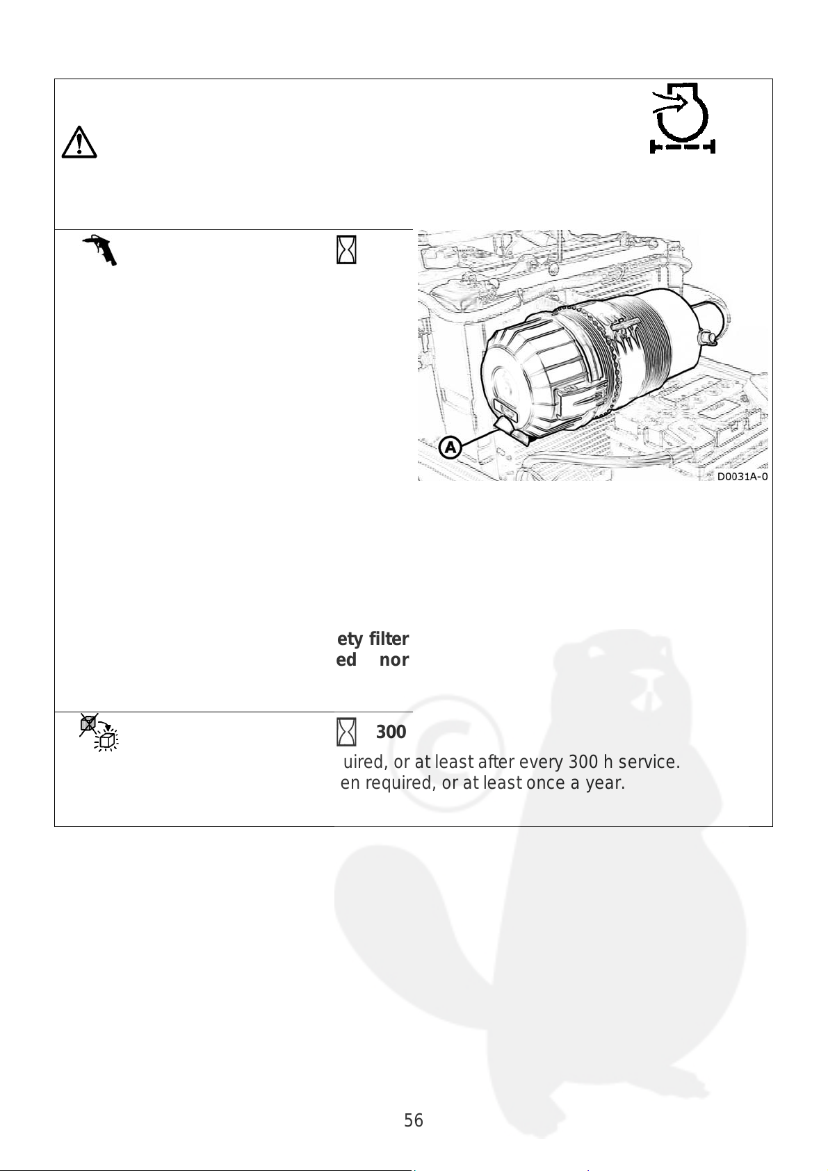
Dry air filter
WARNING: Stop the engine and wait until it has cooled down
before proceeding with any servicing operations.
Clean
Clean drain valve A when required, or at
least once a week.
Clean the filter whenever the warning light
comes on or when necessary, after
evaluating the environmental conditions in
which the machine works (dusty, dry, etc.).
Proceed as described below:
• release and remove the cover.
• remove the external filter.
• blow a jet of compressed air (maximum
pressure 3 BAR) from the inside
towards the outside.
• fit the filter back into its housing.
• close with the cover, with the drain valve
in the lowest position.
DO NOT remove the internal safety filter
(it must neither be cleaned nor
damaged).
Replace
Replace the external filter when required, or at least after every 300 h service.
Replace the internal safety filter when required, or at least once a year.
50
300
56
Page 57
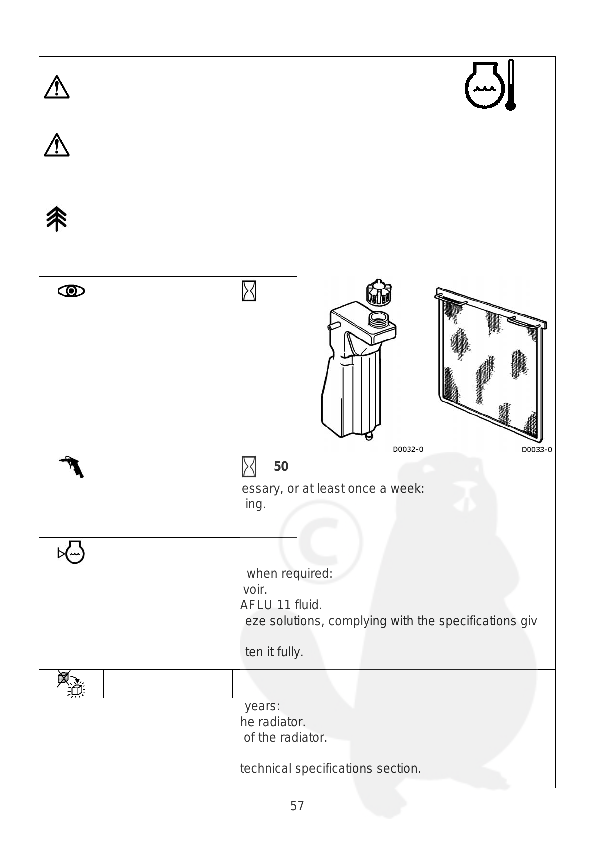
Cooling system
WARNING: Stop the engine and wait until it has cooled down
before proceeding with any servicing operations.
Never open the radiator’s expansion tank whilst the engine is
hot since the cooling fluid could cause burns as it is under
pressure and very hot.
WARNING: Do not dispose of fluids such as fuels, lubricants,
coolants and other various liquids, in the environment.
Check
• Check the level of the cooling fluid.
• Make sure that the radiator guard is
clean.
• Check the belt tension (see engine’s
operation and maintenance manual)
• Every so often, check to make sure that
all the pipe clamps are well tightened.
Clean
Clean the radiator guard when necessary, or at least once a week:
• Remove the guard from its housing.
• Use compressed air.
Top up level
Top up the level of the cooling fluid when required:
• Remove the plug from the reservoir.
• It is advisable to use FIAT PARAFLU 11 fluid.
• It is also advisable to use antifreeze solutions, complying with the specifications given
on the relative package.
• Screw the plug back on and tighten it fully.
8
50
Change
Change the cooling fluid every two years:
• Unscrew the plug at the top of the radiator.
• Unscrew the plug at the bottom of the radiator.
• Empty the circuit.
Capacity of the circuit: consult the technical specifications section.
57
Page 58

Transmission assembly
Gearbox housing, rear differential, power lift
These parts of the tractor use the same oil as the transmission.
WARNING: Do not dispose of fluids such as fuels, lubricants,
coolants and other various liquids, in the environment.
Check
Check the oil level by means of the dipstick
(MIN-MAX )
If necessary, top up with oil of the
recommended type.
Clean
Keep the following parts clean:
• the oil bleeder plug on top of the power lift housing, under the seat.
• the zone surrounding the plug with the dipstick.
50
58
Page 59

Clean
A
A
400
Clean the transmission oil filter:
• after the first 50 hours service
• whenever the oil is changed
• after every 400 hours service
• when the red clogged oil filter indicator
light comes on
To clean the filter:
• unscrew the bolts that fix the cover
• remove the filter
• wash with gasoline or diesel fuel
• dry with compressed air
• fit the cover back on and close it.
Top up level
Check the oil level by means of the dipstick
(MIN-MAX )
If necessary, top up with oil of the
recommended type.
Change
800
Change the transmission oil with 20 kg of
new oil.
The recommended type of oil is
GIP SUPER TRACTOR UNIVERSAL
SAE 15W/40
Oil draining: plug A
Oil filling: plug with dipstick (MIN-MAX )
llow the oil to settle before checking the
new level.
Change the transmission oil filter as
necessary.
59
Page 60
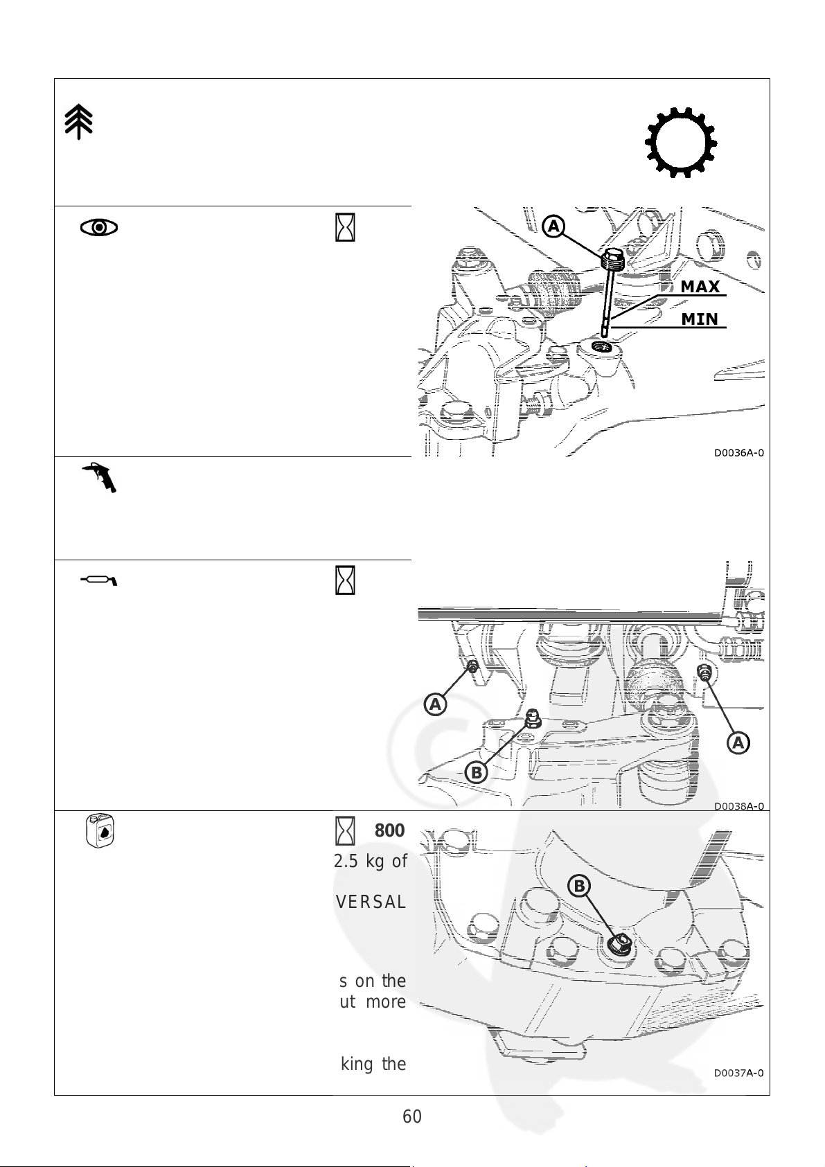
Mod.35-40 front axle
A
A
WARNING: Do not dispose of fluids such as fuels, lubricants,
coolants and other various liquids, in the environment.
Check and
Top up
50
Check the oil level with the dipstick (MINMAX )
If necessary, top up with oil of the
recommended type.
Clean
Keep the following part clean:
• the zone surrounding the plug with dipstick.
Greasing
50
Grease the following parts:
A front axle pivot pin (2 lubricators).
B the hub kingpins
(2 lubricators: right and left)
It is advisable to use
AGIP GREASE LP2
Change
800
Change the transmission oil with 2.5 kg of
new oil. The recommended oil is
GIP SUPER TRACTOR UNIVERSAL
SAE 15W/40
Oil draining: plug B
It is advisable to unscrew the plugs on the
hubs to allow the oil to drain out more
easily.
Oil filling: plug A (MIN-MAX)
llow the oil to settle before checking the
new level.
60
Page 61
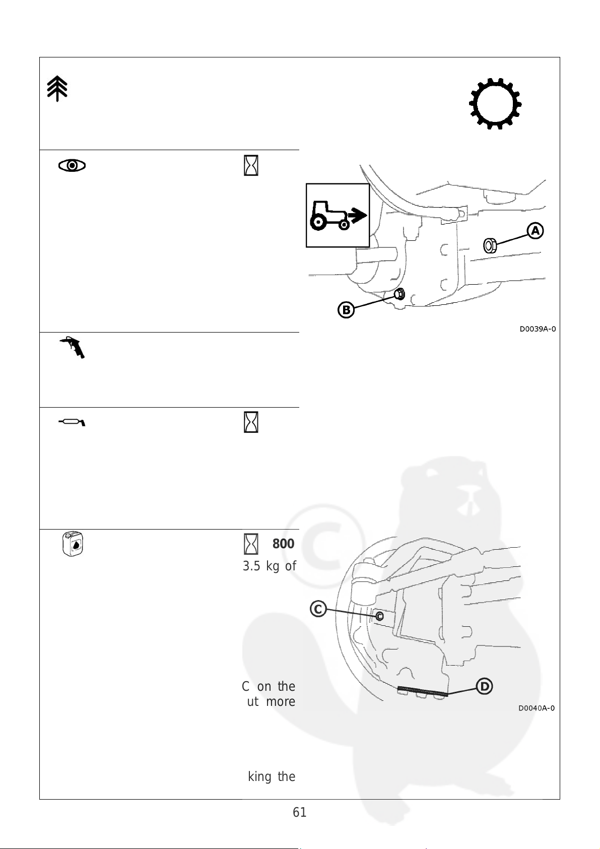
Mod.45 front axle
WARNING: Do not dispose of fluids such as fuels, lubricants,
coolants and other various liquids, in the environment.
Check and
Top up
Check the oil level through plug A
If necessary, top up with oil of the
recommended type.
Clean
Keep the following part clean:
• the zone surrounding plug A.
Greasing
Grease:
• the front axle pivot pin (2 lubricators).
It is advisable to use
AGIP GREASE LP2
50
50
Change
Change the transmission oil with 3.5 kg of
new oil.
The recommended oil is
Agip Rotra MP SAE 80W/90
Oil draining: plugs B and D
It is advisable to unscrew plugs C on the
hubs to allow the oil to drain out more
easily.
Oil filling: plug A
Allow the oil to settle before checking the
new level.
800
61
Page 62

Main clutch
Check
Periodically check the idle travel of the
control pedal.
A = 20mm
Adjust
To adjust the pedal’s travel:
• loosen the check nut
• operate the adjuster
• tighten the check nut
• check the idle travel.
Replace
If necessary, have the clutch assembly replaced by an authorized workshop. Only use a
genuine spare.
62
Page 63
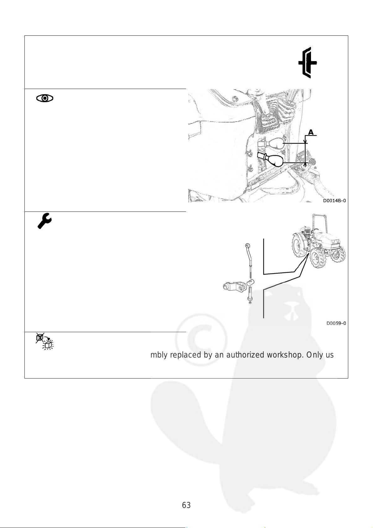
Rear power take-off clutch
Check
Periodically check the idle travel of the
control pedal.
A = 20mm
Adjust
To adjust the pedal’s travel:
• loosen the check nut
• operate the adjuster
• tighten the check nut
• check the idle travel.
Replace
If necessary, have the clutch assembly replaced by an authorized workshop. Only use a
genuine spare.
63
Page 64

Rear differential lock
The differential lock is controlled mechanically by means of a
pedal that operates a hydraulic cylinder.
WARNING: Do not dispose of fluids such as fuels, lubricants,
coolants and other various liquids, in the environment.
Check
Check the level of the hydraulic oil in the
tank.
The tank must be three-quarters full.
Top up level
If necessary, top up the level in the tank.
Recommended oil AGIP ATF II D
Change
The oil in the hydraulic circuit must be changed every 2 years.
Recommended oil AGIP ATF II D
150
X
Final drive lever
Greasing
Grease the final drive lever.
Recommended grease
AGIP GREASE LP2
50
64
Page 65

Brakes
A
The braking system is controlled mechanically by means of two
pedals that operate two hydraulic cylinders.
WARNING: Do not dispose of fluids such as fuels, lubricants,
coolants and other various liquids, in the environment.
Check
Check the level of hydraulic oil in the
reservoir.
The reservoir must be three-quarters full.
Adjust
djust the brakes if brake pedal travel becomes excessive or when one of the wheels
brakes in a different way.
IMPORTANT: Only your dealer or specialized personnel may adjust the braking
system.
150
Top up level
Top up the level in the reservoir when necessary.
Recommended oil
AGIP ATF II D
Change
The oil in the hydraulic circuit must be changed every 2 years.
Recommended oil
AGIP ATF II D
X
65
Page 66

Electrical system
WARNING: Always disconnect the battery’s ground cable (negative pole with the
“-“ symbol) before working on the electrical system.
Battery
WARNING: Work on the battery requires particular care: the
electrolyte is corrosive and the gases released are
inflammable.
DISPOSAL: Exhausted batteries must be consigned to
authorized disposal centers. Do not dispose of batteries in
the environment or in normal urban waste bins.
Check
Make sure that the battery is firmly fixed to the tractor.
Clean
Keep the battery clean with a damp, antistatic cloth.
Keep the battery poles and cable terminals clean.
Greasing
Lightly grease the poles and terminals when necessary.
Use Vaseline-based grease, not normal grease.
50
This type of battery cannot be topped up.
WARNING: DO NOT OPEN THE BATTERY
If the tractor is not used for a long period of time:
• charge the battery as indicated by the manufacturer.
• disconnect both the cables.
• store the battery in a cool, dry, well ventilated place.
If the battery must be replaced, make sure the new one possesses identical technical
specifications (the values are given on the actual battery itself).
Top up level
Idle periods
Replace
66
Page 67

Headlights
If the tractor must be driven on the public highways, the
headlights must comply with the Highway Code regulations in
force in the country of use.
Adjust
Consult specialized personnel in possession of the specific tools required in order to
have the headlights adjusted correctly.
Replace
Replace burnt-out light bulbs with others if identical technical characteristics (see
indications on the bulbs themselves).
Consult specialized personnel if in doubt.
67
Page 68

Fuses
The electrical system is protected by fuses against short circuits
or abnormal power draw.
The tractor has a main fuse. This fuse protects the entire
electrical system.
Replace
Replace burnt-out fuses with others possessing identical technical specifications (the
relative indications are given on the fuses themselves).
Consult specialized personnel if in doubt.
Fuse functions:
N°
A
B
C
D
E
F
G
H
A
Function
20A Power socket power supply
15A Horn power supply
Rh front side light
5A
Lh rear side light
7-pin socket
Lh front side light
License plate light
5A
Rh rear side light
7-pin socket
Brake light power supply
5A
Four-wheel drive switch
PTO switch
Multi-function dashboard
10A
Fuel pump motor
Motor stop coil
7.5A
Lh dipped beam
7.5A
Rh dipped beam
10A 7-pin socket power supply
I
+15 power supply
10A
L
M
N
Hazard light switch
+30 power supply
10A
Hazard light switch
Rh driving beam
15A
Lh driving beam
Main fuse
50
General protection of electrical
A
system
68
Page 69
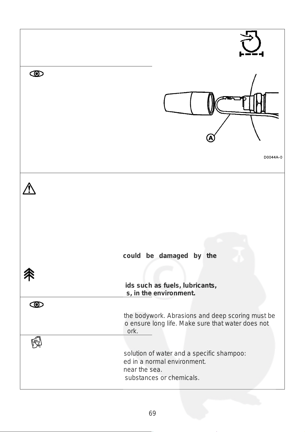
Engine air filter clogging sensor
Check
Check to make sure that the engine air
filter clogging sensor is in the right position.
If servicing is required, make sure that the
sensor is assembled correctly and
protected against adverse weather
conditions as indicated in the figure.
It is essential for cable A, that connects to
the electrical system of the machine, to be
routed through the lower part of the sensor.
If the protection is positioned incorrectly,
this could cause serious damage to the
engine’s air intake circuit.
Bodywork
WARNING: If you use jets of pressurized water for cleaning,
direct the jet well away from:
• tyres
• hydraulic pipes
• radiator
• electrical components
• soundproofing seals
and other components that could be damaged by the
pressure of the water.
WARNING: Do not dispose of fluids such as fuels, lubricants,
coolants and other various liquids, in the environment.
Check
Periodically check the condition of the bodywork. Abrasions and deep scoring must be
repaired by specialized personnel to ensure long life. Make sure that water does not
remain in hidden parts of the bodywork.
Clean
Clean the bodywork with a normal solution of water and a specific shampoo:
• when needed if the tractor is used in a normal environment.
• frequently if it is used in places near the sea.
• immediately after using organic substances or chemicals.
69
Page 70

Air conditioning system
WARNING: Never tamper with the air conditioning system:
always contact specialized personnel.
WARNING: Keep naked flames and heat sources well away
from the air conditioning system.
WARNING: Never loosen unions and/or tamper with pipes:
the system is pressurized. The refrigerant can freeze the skin
and eyes.
WARNING: Do not dispose of fluids such as fuels, lubricants,
coolants and other various liquids, in the environment.
Check
Periodically check:
• the condition of the pipes and unions.
• that the pulley and compressor screws are well tightened.
• the tension of the compressor belt.
Have the following parts checked annually by specialized personnel:
• compressor oil level
• tightness of the system (using special tools)
Clean
Clean the following components with compressed air when required, or at least once a
week:
• the cab radiator’s side ventilation grilles
• the cab radiator / fan compartment
They are installed on the top part of the roof.
You are advised to contact an Authorized Assistance Center if there is a great deal of
dirt inside the radiator.
Adjust
Adjust the tension of the compressor belt when required.
70
Page 71

TECHNICAL SPECIFICATIONS
General specifications
Engine
Transmission
Steering
system
Power takeoff
lift
power lift
Hydraulic
circuit
Make
Model
Power rating
Other data
Tank capacity
(reserve)
Cooling system
N° speed gears
Type of clutch
Diameter
Reverse shuttle
Speed
Steering angle
Independent rear PTO
Optional
Shaft profile
Rotation direction
Rear
Synchronized with engine
Shaft profile
Ratio of synchronized
PTO rev. / wheel turn
Lifting capacity
Three-point hitch
Lifting capacity
Three-point hitch
Pump capacity
kW
(CV)
l
l
kph
kg
kg
l /
min.
35 40 45
Lombardini
LDW1503 LDW1603 LDW2204
24 (33) 27 (36) 32 (44)
See engine’s operation and
maintenance manual
40 (5) 40 (5) 40 (5)
7 7 8.5
12 + 4 reverse + 12 with reverse shuttle
Dry
9”
Synchronized
30
55°
540 rpm (with 2518 rpm engine rate)
1000 rpm (with 2500 rpm engine rate)
2000 rpm (with 2500 rpm engine rate)
1” 3/8 ASAE with 6 splines
clockwise
counter-clockwise
1” 1/8 ASAE with 6 splines
21.83
1400 Rear power
Class 1
800 Optional front
Class 1N
33
71
Page 72
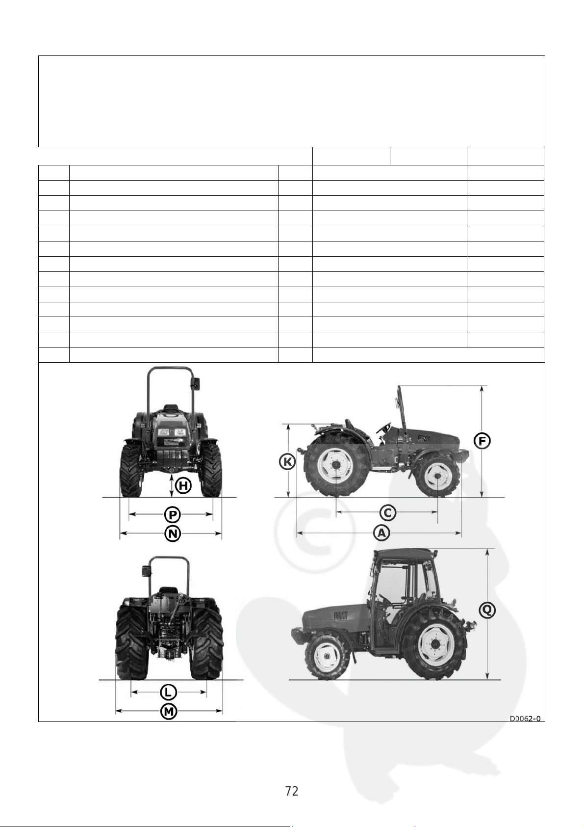
Dimensions and weights
A Min-max length
N/M Min-max width
F Min-max height to chassis
Q Min-max height to cab
K Min-max height to seat
H Min-max ground clearance
C Wheelbase
P Min-max front track
L Min-max rear track
Minimum turning radius with brakes
Weight with safety frame
Weight with cab
Front ballast
mm
mm
mm
mm
mm
mm
mm
mm
mm
m
kg
kg
kg
35 40 45
2485 -2560 2575 - 2650
1060 -1600 1060 - 1600
1825 -1900 1825 - 1900
2140 - 2230 2140 - 2230
975 - 1050 975 - 1050
250 - 330 250 - 330
1620 1685
900 - 1200 900 - 1200
860 - 1270 860 - 1270
2.8 3
1380 1450
1480 1550
15 x 5
72
Page 73

Speeds
73
Page 74

Recommended lubricants
Comply with the following specifications if other lubricant makes are used:
Agip ATF II D Oil
Viscosity at 40° C (mm2/s)............... 34
Viscosity at 100° C (mm2/s)............... 7
Viscosity at -40° C (mPa.s).........45000
Viscosity index................................ 183
V.A. flash point (°C)........................ 200
Pour point (°C).................................-42
Colour………………………………red
Volume mass at 15 °C (kg/l)........0.865
Agip Supertractor oil
Universal SAE 15W/40
Viscosity at 40° C (mm2/s)............. 100
Viscosity at 100° C (mm2/s).......... 13.6
Viscosity at -15° C (mPa.s)...........3300
Viscosity index................................ 135
Flash point V.A. (°C)....................... 220
Pour point (°C).................................-27
Absolute gravity at 15 °C (Kg/l)... 0.884
Agip Rotra MP SAE 80W/90 oil
Viscosity at 40° C (mm2/s)............. 144
Viscosity to 100° C (mm2/s)............. 15
Viscosity at -26° C (mPa.s).......110000
Viscosity index................................ 104
Flash point V.A. (°C)....................... 210
Pour point (°C).................................-27
Absolute gravity at 15 °C (Kg/l)... 0.900
Agip GR LP 2 grease
NLGI consistency ............................... 2
Worked penetration (dmm)............. 280
Dropping point ASTM (°C).............. 182
Timken OK Load (lbs)....................... 50
Basic oil viscosity at 40°C (mm2/s) 160
JD:
JD:
JD:
JD:
Standard:
Standard:
Standard:
Standard:
74
Page 75

Page 76

Published by the TECHNICAL PUBLICATIONS OFFICE
Serial N° 06380979 / 2th Edition
Printed in Italy
 Loading...