

Gold Medal Tornado 3005SS, Whirlwind 3008SS, Tornado, Deluxe Whirlwind, 3008SS Instruction Manual
...Page 1
Tornado Model 3005SS
Whirlwind
Model 300
8SS
Part No. 42117
Tornado
Deluxe
Whirlwind
and
Instruction Manual
Model No. 3005SS and 3008SS
Cincinnati, OH 45241-4807 USA
Page 2
A
#3005SS,
#3008SS
, 3015
T
ornad
o
Whirlwin
d Flos
s Machine
1
DANGER
DANGER
cause property damage, injury, or death. Any alterations to this equipment will
WARNING
WARNING
WARNING
WARNING
and
SAFETY PRECAUTIONS
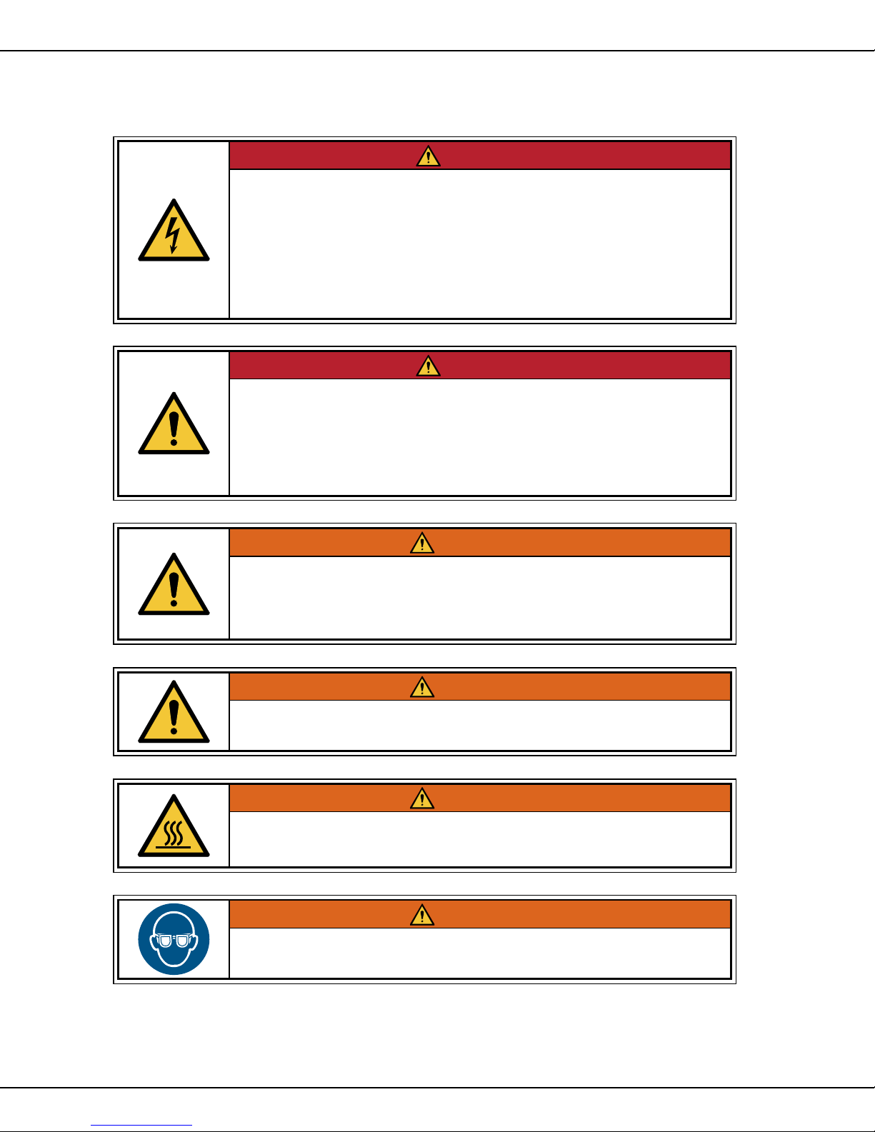
Machine must be properly grounded to prevent electrical shock to personnel.
Failure to do so could result in serious injury, or death.
DO NOT immerse any part of this equipment in water.
DO NOT use excessive water when cleaning.
Keep cord and plug off the ground and away from moisture.
Always unplug the equipment before cleaning or servicing.
Make sure all machine switches are in the OFF position before plugging the
equipment into the receptacle.
Improper installation, adjustment, alteration, service, or maintenance can
void the warranty and may cause a dangerous condition. NEVER make
alterations to this equipment. Read the Installation, Operating, and
Maintenance Instructions thoroughly before installing, servicing, or operating
this equipment.
008_051514
014_051514
Floss head rotates at high speeds. Operator MUST keep hands and face
clear of the floss head to avoid injury. Operator must wear eye protection.
Keep all spectators at a reasonable distance, and use a Floss Bubble for
added customer protection.
015_062714
Keep all foreign objects out of floss head. To avoid eye injury, DO NOT fill
floss head with sugar while the head is on and rotating.
016_010914
Burn Hazard. DO NOT touch spinner head. Allow to cool before cleaning or
servicing. Avoid contact with molten sugar.
006_092414
ALWAYS wear safety glasses when servicing this equipment.
010_010914
LL MODELS
Page 3
A
#3005SS,
#3008SS
, 3015
T
ornad
o
Whirlwin
d Flos
s Machine
2
WARNING
WARNING
WARNING
WARNING
and
SAFETY PRECAUTIONS (continued)
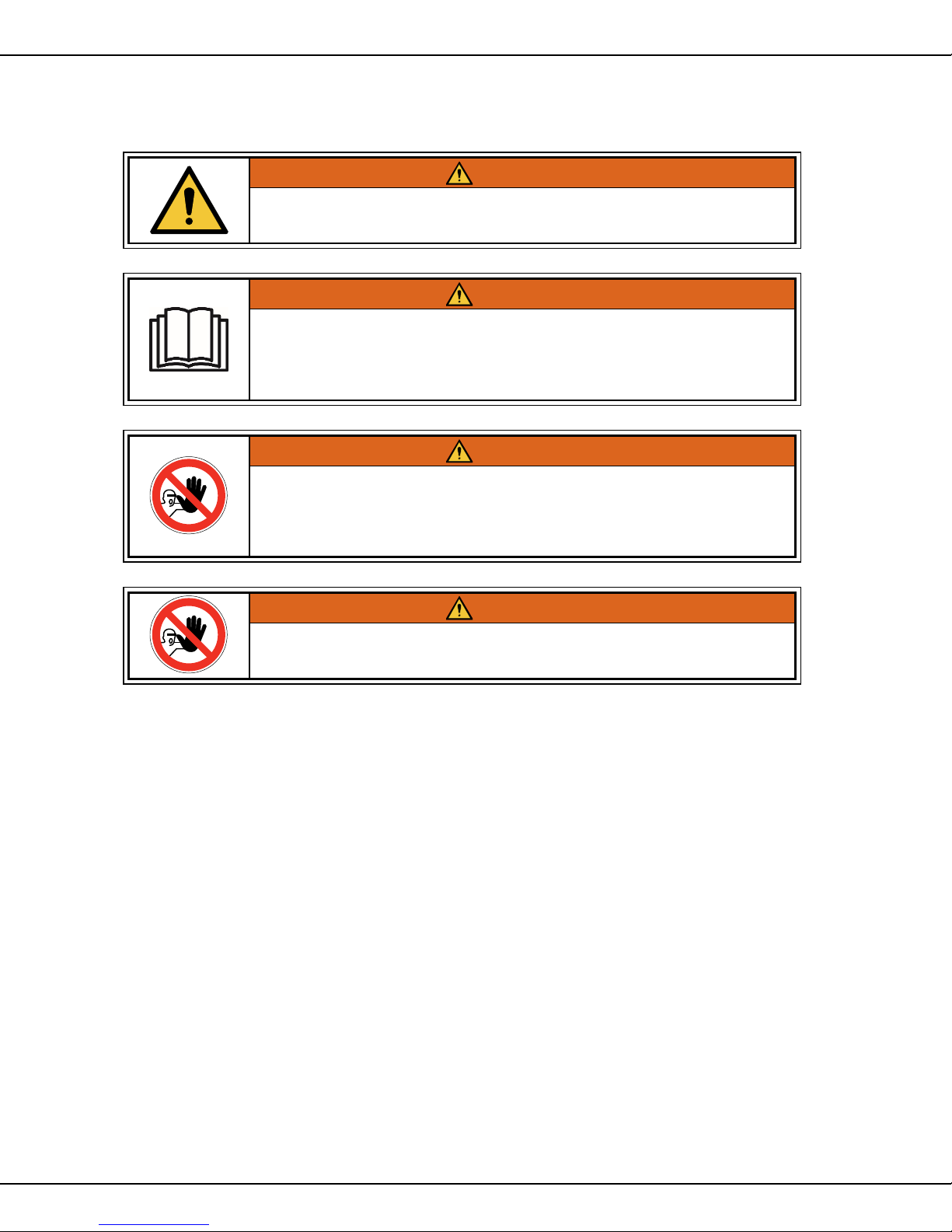
No user serviceable parts inside. Refer servicing to qualified service
personnel.
Read and understand operator’s manual and all other safety instructions
before using this equipment. To order copies of the operator’s manual go to
gmpopcorn.com or write to Gold Medal Products Co., 10700 Medallion Drive,
Cincinnati, OH 45241 USA 1-(800)-543-0862
DO NOT allow direct contact of this equipment by the public when used in
food service locations. Only personnel trained and experienced in the
equipment operation may operate this equipment.
Carefully read all instructions before operation.
011_051514
022_060215
012_010914
This machine is NOT to be operated by minors.
007_010914
Note: Improvements are always being made to Gold Medal’s equipment. This information
may not be the latest available for your purposes. It is critical that
you call Gold Medal’s Technical Service Department at 1-800-543-0862 for any
questions about your machine operations, replacement parts, or any service
questions. (Gold Medal Products Co. does not assume any liability for injury due
to careless handling and/or reckless operation of this equipment.)
LL MODELS
Page 4

A
#3005SS,
#3008SS
, 3015
T
ornad
o
Whirlwin
d Flos
s Machine
3
and
INSTALLATION INSTRUCTIONS
INSPECTION OF SHIPMENT
After unpacking, check thoroughly for any damage which may have occurred in transit. Claims should be
filed immediately with the transportation company. The warranty does not cover damage that occurs in
transit, or damage caused by abuse, or consequential damage due to the operation of this machine, since it
is beyond our control (reference warranty in back of manual).
MANUAL
Read and understand the operator’s manual and all other safety instructions before using this equipment.
To order copies of the operator’s manual go to gmpopcorn.com or write to Gold Medal Products Co., 10700
Medallion Drive, Cincinnati, OH 45241 USA 1-(800)-543-0862.
SETUP
Remove all tape and other packing material.
Remove the shipping support angles which protect the suspension springs during transit.
Retain these for future use when you transport the machine.
LOCATION
Place the floss machine in the Unifloss Stand or on a suitable table or bench. Ventilation around
the machine is important to insure long life of the components. Be sure to allow a minimum of
six inches around each side and no restrictions from supplies or debris in and around ventilation
openings.
Wash the floss pan thoroughly with soap and water. Install the floss pan on the machine with the
floss head extending up through the center of the pan. Push down on the bottom of the pan to
insure it is seated firmly on the pan supports.
As a last precaution before plugging in the machine, look inside the head assembly and make
sure the floss ribbons (heating elements) have not shaken out of the band during transportation.
If the ribbons are out of the band, they can be easily pushed back into place with your index
finger.
LL MODELS
Page 5

A
#3005SS,
#3008SS
, 3015
T
ornad
o
Whirlwin
d Flos
s Machine
4
DANGER
CAUTION
and
ELECTRICAL REQUIREMENTS
The following power supply must be provided:
3005SS and 3008SS: 120 V~, 2400 W, 60 Hz
Machine must be properly grounded to prevent electrical shock to personnel.
Failure to do so could result in serious injury, or death.
DO NOT immerse any part of this equipment in water.
DO NOT use excessive water when cleaning.
Keep cord and plug off the ground and away from moisture.
Always unplug the equipment before cleaning or servicing.
Make sure all machine switches are in the OFF position before plugging the
equipment into the receptacle.
A certified electrician must furnish sufficient power for proper machine operation and install any supplied
receptacle. We recommend this equipment be on a dedicated and protected circuit. Failure to wire
properly will void the warranty and may result in damage to the machine. It is Gold Medal Products Co.’s
recommendation that this machine be plugged directly into a wall outlet. The use of extension cords is
not recommended due to safety concerns, and may cause sacrificed and/or reduced performance. Make
sure cord is located to prevent a trip hazard or unit upset.
008_051514
BEFORE YOU PLUG IN MACHINE
1. Make sure all machine switches are in the OFF position before plugging the equipment into
the receptacle.
2. Make sure the wall outlet can accept the grounded plugs (where applicable) on the power
supply cord.
3. The wall outlet must have the proper polarity. If in doubt, have a competent electrician
inspect the outlet and correct if necessary.
4. DO NOT use a grounded to un-grounded receptacle adapter (where applicable).
5. Install the unit in a level position.
If the supply cord is damaged, it must be replaced by Gold Medal Products Co.,
its service agent or similarly qualified persons in order to avoid a hazard.
039_080614
LL MODELS
Page 6

A
#3005SS,
#3008SS
, 3015
T
ornad
o
Whirlwin
d Flos
s Machine
5
and
CONTROLS AND THEIR FUNCTIONS
TORNADO AND DELUXE WHIRLWIND CONTROLS
MOTOR SWITCH
DPST switch which serves as a master OFF-ON switch and energizes the cooling fan and
spinner head drive motor.
NOTE: The drive motor is equipped with an internal centrifugal safety switch which makes
contact when the floss spinner head reaches approximately 2050 RPM, thus completing the
heat circuit. This mechanism provides a safety circuit for the heating ribbons in the case of a
motor malfunction.
HEAT SWITCH
Three position DPDT switch: Emergency, Off, Normal
Emergency (Red position)
This position applies the fixed transformer to increase the line voltage 35 volts (increase
the heat in the spinner head) and provide for faster heating. This position should be used
when low supply voltage conditions exitst. While this position is ordinarily used for startup under normal operating conditions, it might also be used in situations where the
ribbons or equipment have had extensive use.
Off
With the switch in this position, the floss ribbons will not heat.
Normal (Blue position)
This position applies the fixed transformer to decrease the line voltage by 35 volts
(decrease the heat to the spinner head) and provide a normal operating range.
HEAT CONTROL
This is a variable transformer used to provide finer control across the pre-selected range of
the heat switch. It increases or decreases the voltage to the spinner head (raising or lowering the heat to the head). On the door panel surrounding the heat knob are red and blue
graduated scales from 1 to 9 designed to correspond with the setting of the heat switch. For
example, if the heat switch is set to normal (blue), adjustments to the ribbon temperatures
using the heat control are made reading the blue scale. The greater the number, the greater
the heat.
X-15R WHIRLWIND CONTROLS
MAIN POWER AND MOTOR SWITCH
DPST switch which serves as a master OFF-ON switch and energizes the cooling fan and
spinner head drive motor. NOTE: The drive motor is equipped with an internal centrifugal
safety switch which makes contact when the floss spinner head reaches approximately
2050 RPM, thus completing the heat circuit. This mechanism provides a safety circuit
for the heating ribbons in the case of a motor malfunction.
HEAT RANGE SWITCH
This is a 4-position tap switch with "A", "B", "C" and "OFF" positions. The "A" position corresponds to the highest heating potential, "B" is an intermediate range, and "C" corresponds to
the coolest position.
HEAT CONTROL FINE TUNING
This is a rheostat which allows you to make small, incremental adjustments to the spinner head
ribbon temperatures. The higher the number, the greater the voltage and temperature.
LL MODELS
Page 7

A
#3005SS,
#3008SS
, 3015
T
ornad
o
Whirlwin
d Flos
s Machine
6
DANGER
WARNING
and
MAKING FLOSS
1. Before operating your machine, read this section on how to make floss.
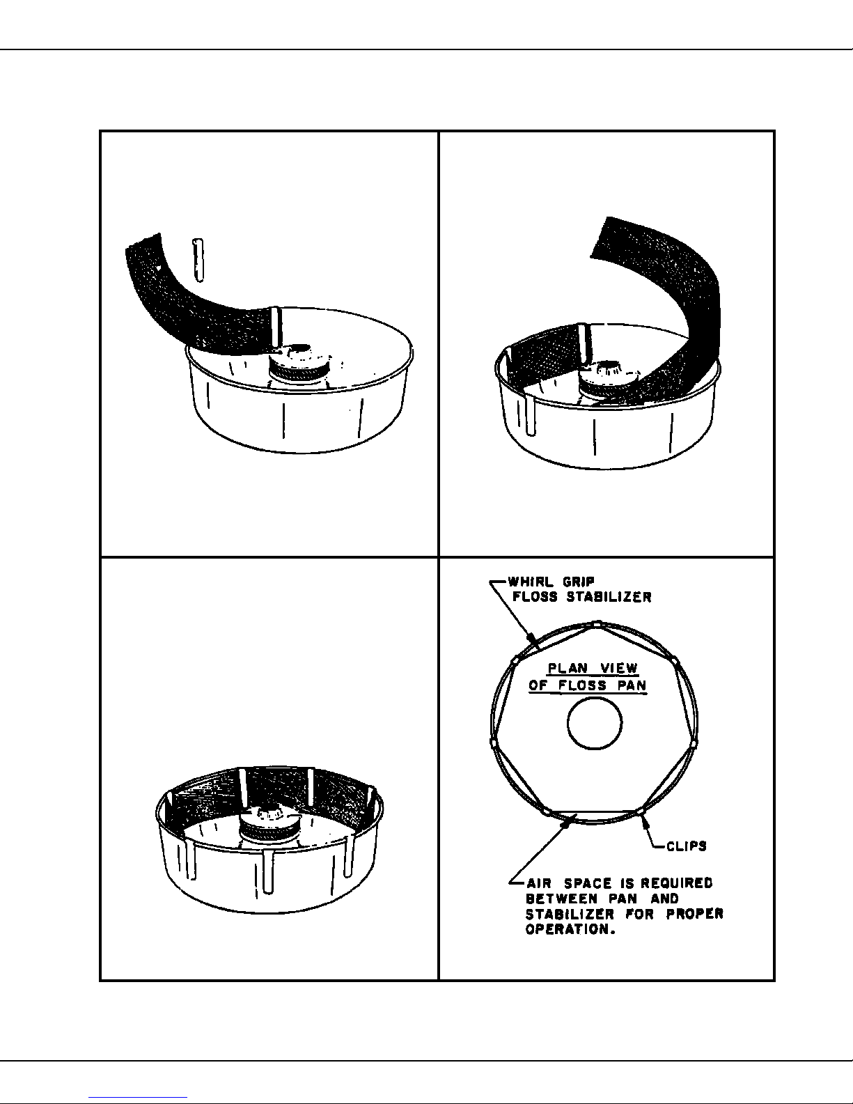
2. Using a damp cloth, moisten the inside of the floss pan. This will cause the floss to adhere to
the sides of the pan. The Whirlgrip Floss Stabilizer Model No. 3010 works more effectively to
prevent floss from leaving the pan and is offered by Gold Medal at a modest price. See the
illustration on page 6 which shows proper installation of the Whirlgrip Floss Stabliizer.
3. After reading this entire section, operate your machine as described in the operating
instructions for your machine following this section.
4. Pay attention to the direction of the floss as it is spun out of the head. It should be thrown
against and adhere to the sides of the floss pan. Attached to the top plate of the spinner head
are two floaters, these give additional air current for floss control. By twisting the leading edge
of the floaters down, you get more lift and the floss will go upward. With the leading edge up,
the floss will go down. A little practice should give you good control in any climatic condition.
5. To pick up floss: Once you practice awhile, anyone can be an expert at rolling the web of
cotton candy onto the cone. First, pick up the cone. If it sticks in the stack of cones, do not
pull, but twist it off the stack. Hold an inch or two of the pointed end of the cone between your
two fingers and your thumb. With a light flicking action, break the web of floss that is building
up in the pan. Usually some floss will stick to the cone. Lift up the cone with the ring of floss
attached and, by rotating the cone, wind the floss onto it. Do NOT roll floss onto the cone
while it is inside the pan. This will just pack the floss onto the cone, causing you to use more
floss to fill the cone, and result in less cones of floss per load of sugar. For additional help,
reference Floss Making Procedures section.
If you experience difficulty in getting the floss to stick to the cone, it will be helpful to pass the
cone over a damp sponge. One pass over the sponge should cause the floss to stick, allowing
easier floss pick-up. Many experienced operators prefer to lift the ring out of the pan and, with a
flick of the wrist, turn the ring into a figure eight and whip it around the cone. This leaves giant air
pockets and makes it appear that you are serving a larger portion.
Shut Down Procedure
When completing operation for the day (or any prolonged period), run all the sugar out of the
floss head. When empty, turn the heat to highest position for approximately one minute to
“clean” the band by baking off remaining sugar. NEVER put water in the floss head.
Cleaning Instructions
Machine must be properly grounded to prevent electrical shock to personnel.
DO NOT immerse in water.
Always unplug the equipment before cleaning or servicing.
025_020314
Burn Hazard. DO NOT touch spinner head. Allow to cool before cleaning or
servicing. Avoid contact with molten sugar.
Unplug the machine and wait for the floss head to cool down to room temperature. Wipe all
surfaces with a clean, damp cloth. Make sure all parts are dry before resuming operation.
006_010914
LL MODELS
Page 8
A
#3005SS,
#3008SS
, 3015
T
ornad
o
Whirlwin
d Flos
s Machine
7
and
SUGAR FOR YOUR COTTON CANDY
Our ready to use FLOSSUGAR is the preferred sugar for your new cotton candy machine, but
and 100% pure Cane or Beet Sugar will do just fine. Our FLOSSUGAR gives you good rich
colors, and great flavors, too. It is packed in handy half-gallon sealed cartons, with E-Z pour
spout for filling your machine. FLOSSUGAR comes in 8 flavors, and you can easily change
colors for greatest variety, and best sales.
If you want to “Mix Your Own”—use our FLOSSINE, and please follow our directions. If you
want a deeper color, slightly dampen the mixed sugar—use a tablespoon of water per five
pounds of sugar—sprinkle water over sugar, and mix well. DO NOT USE EXCESS COLOR—
too much color will mess up the ribbons on your machine, and could impart a bitter taste to the
candy. There is a limit as to how dark you can make cotton candy-that’ s because it is 98% air;
and we cannot color the air.
Today 99% of the sugar manufactured is “Extra Fine Granulated” which does have some small
particles which can slip thru the ribbons without being melted. If this becomes objectionable,
you can seek out Medium Coarse, or sanding sugars. The larger crystal size will require a little
more heat to melt. Read the label on the bag of sugar—today we see some “Free Flowing”
sugar for restaurants, and it contains cornstarch, which will burn onto your ribbons, clogging
them rapidly. We have also seen some cheap off-brand “sugar” which is a blend of sugar and
dextrose or corn syrup. This product makes very poor cotton candy. Please make sure you get
good sugar for your cotton candy machine.
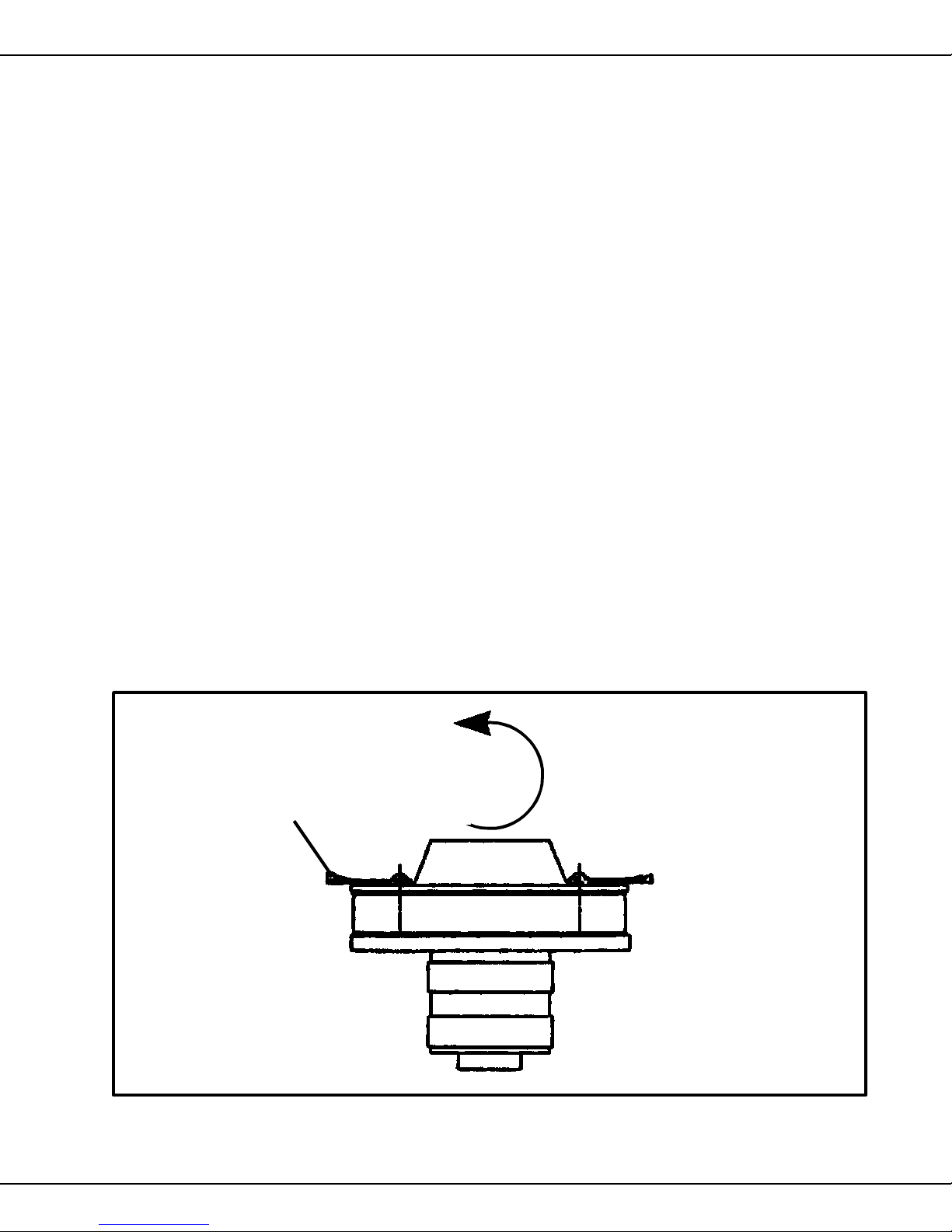
FLOATER ADJUSTMENT
Form leather floaters as shown. This creates a lifting action to float the floss across the gap to the
side of the floss pan.
Leather
Floater
ROTATION
LL MODELS
Page 9
A
#3005SS,
#3008SS
, 3015
T
ornad
o
Whirlwin
d Flos
s Machine
8
and
INSTALLATION OF WHIRL GRIP FLOSS STABILIZER
1
2
3
4
LL MODELS
Page 10
A
#3005SS,
#3008SS
, 3015
T
ornad
o
Whirlwin
d Flos
s Machine
9
and
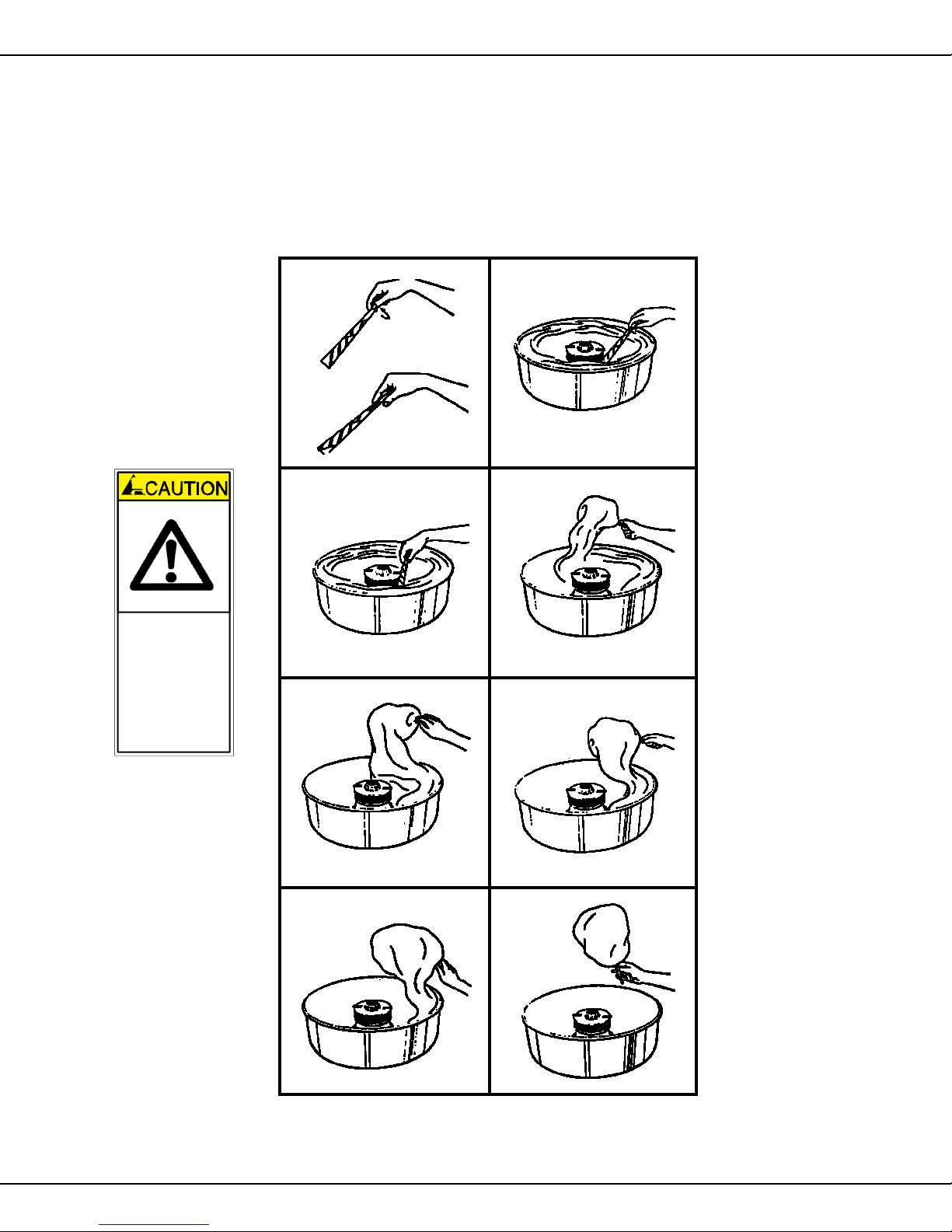
FLOSS MAKING PROCEDURES
Add Flossugar only while motor is off. Then, manually spin the head to balance.
Keep hands
away from
spinning
head!
This will eliminate excessive vibration of the head.
When adding sugar, always fill about 90% full.
DO NOT OVERFILL!
1
Grip Rotation
Wind the web of
sugar onto the cone
3
Break into web of floss
with the cone.
5
Remember:
Let the machine do the work.
2
Grip cone as shown.
4
Lift web of floss from the
pan and roll onto the cone.
6
7 8
LL MODELS
Page 11

A
#3005SS,
#3008SS
, 3015
T
ornad
o
Whirlwin
d Flos
s Machine
10
and
OPERATING INSTRUCTIONS
TORNADO AND DELUXE WHIRLWIND
1. Plug in floss machine.
2. Before turning on the motor switch and with the spinner head stationary, fill floss head
about 90% full with sugar. Do NOT overfill! Whenever you add sugar to the floss head,
always fill it abour 90% full. This is necessary to obtain a balanced condition in the floss
head or excessive vibration will occur. Never add sugar when motor is running. After
adding Flossugar, manually rotate head to balance.
3. Flip Motor Switch to On position.
4. Flip the Heat Switch to Emergency position. This is for a fast warm up. Turn Heat Control
up until voltmeter indicator arrow moves into the red start area.
5. The machine should begin to make floss in a matter of a few seconds. After floss is being
produced, place Heat Switch in Normal position. Adjust the Heat Control until the voltmeter
X-15R WHIRLWIND
indicator arrow moves into the green run area.
CAUTION
Never operate equipment for prolonged period of time with the
Heat Control in a position that causes the sugar to smoke. This
will result in excessive carbonization of the ribbon (heat element).
If you smell burning sugar or see smoke, reduce the heat.
6. Once you find the ideal setting for the Heat Control, you should be able to operate near this
position each time.
7. Read the section in this manual on Making Floss before going into full production
1. Plug in floss machine.
2. Before turning on the main power and motor switch, and with the spinner head stationary, fill
the floss head about 90% full with sugar. Do Not Over Fill! Whenever you add sugar to the
floss head, always fill the head about 90% full. This is necessary to obtain a balanced condi
tion in the floss head and eliminate excessive vibration. Never Add Sugar When Motor Is
Running. After Adding flossugar manually rotate head to balance.
3. turn the Main Power and Motor Switch to the On position.
4. Turn Heat Range Switch to position "A". Rotate Heat Control Fine Tuning Knob to Maximum
position (No. 8). This setting will produce the fastest possible warm up.
5. You should start making floss in a few seconds. When the unit gets up to heat, it will probably
start to smoke. Reduce the Heat Control Fine Tuning setting to eliminate the smoke. If you
cannot eliminate the smoking in this manner, turn the Heat Range Switch to position "B" and
set the Heat Control Fine Tunning to postion No. 8 once more. If smoking continues reduce
the Heat Control Fine Tuning setting. If necessary, repeat once more with the Heat Range
Switch on "C".
NOTE:
6. Once you find the ideal Heat Range Switch and Heat Control Fine Tuning positions, you
should be able to operate near these positions each time you operate.
7. Read the section on Making Floss before going into full production.
You can fine tune in all three heat range positions.
LL MODELS
Page 12

A
#3005SS,
#3008SS
, 3015
T
ornad
o
Whirlwin
d Flos
s Machine
11
and
INDOOR COTTON CANDY SUCCESS TIPS
1. The Unifloss Stand: Choose either the complete Unifloss Stand or the top half only and
mount it onto your Snack-N-Treat Bar. The Unifloss Stand plus the Whirl Grip Floss
Stabiizer effectively eliminates all indoor objections. In addition, the new Animated
Motion Sign Effectively helps merchandise the cotton candy.
2. Candy Floss Is Clean: In fact, it is "poly clean" when you sell cotton candy in poly bags.
Cotton candy is never sticky in poly bags. Always make cotton candy on attractive
striped cones and put the floss cone and all in the bag. The "Kid Appeal" comes from
having a circus style serving on the cone. If you sell cotton candy as a pad, you lose this
appeal.
3. Always Use A Printed Cotton Candy Bag: This tends to package the end product more
attractively. It only cost a tenth of a cent more to go first class a tenth of a cent is all it
cost to make every sale a walking advertisement for building your profits.
4. Use The Automatic Floss Bagger: It's as handy as having three hands. The bag is
opened by a stream of air. Hold it open with your free hand and stuff the floss in the bag
cone and all.
5. To Sell More Cotton Candy, you should always rotate your colors often. The easiest
way is to use Flossugar in the eight exciting color-flavor combinations. Simply pour from
the handy half gallon carton into the floss head and presto, you have a new color. Always
change colors as the floss head runs out of sugar.
6. Always Display Cotton Candy: Both the Floss Display Board and the Cotton Candy Tree
hold enough bagged cotton candy to allow you to produce three complete loads-each
a different color. Always display more than one color on the board-it helps to sell more.
7. Point Of Purchase Signs: Paper ppoint of purchase signs are included with each case
of cones.
8. In Store Promotions: it always pays to be able to use the public announcement system
to help announce to the buying public the location of the cotton candy department.
Secondary Display Boards Loaded with product in high traffic areas will also help stimulate
sales. Always suggest the multiple sale - carry one-sixth bushel brown kraft bags to help
your customers carry out a half dozen at a time.
9. External Promotions: coupons in your ad for free Cotton Candy-or for cents off-always pull
in shoppers and build store profits. Free Ad Mats are yours for the asking.
LL MODELS
Page 13

A
#3005SS,
#3008SS
, 3015
T
ornad
o
Whirlwin
d Flos
s Machine
12
and
INSTALLING A UNIFLOSS STAND
There are two halves to a Unifloss Stand. For free-standing installations, use the base and
merely set the top half on it as shown in the drawing below. For In Counter installations,place
the top sectioin of the Unifloss Stand over a cutout in your counter top. A shelf is requiered
under the counter to set the floss machine on. For counter top cutout size and shelf location,
request drawing numbers B-3374 and C-3418 from Gold Medal Products Company.
After the top half of the Unifloss Stand is in position, tilt the floss machine and position the
spinner head in the center of the cutout. NOTE: Make sure shipping support angles are re-
moved as indicated in the installation section of this manual.
Place the spun aluminum pan over the floss head of the machine. Recenter the machine to
provide equal spacing around the pan and cutout.
After connecting the power supply cords, you are ready to make cotton candy. See Operating
Instruction in this manual.
Unifloss Stand
LL MODELS
Page 14

A
#3005SS,
#3008SS
, 3015
T
ornad
o
Whirlwin
d Flos
s Machine
13
DANGER
DANGER
cause property damage, injury, or death. Any alterations to this equipment will
WARNING
CAUTION
and
MAINTENANCE INSTRUCTIONS
Machine must be properly grounded to prevent electrical shock to personnel.
Failure to do so could result in serious injury, or death.
DO NOT immerse any part of this equipment in water.
DO NOT use excessive water when cleaning.
Keep cord and plug off the ground and away from moisture.
Always unplug the equipment before cleaning or servicing.
Make sure all machine switches are in the OFF position before plugging the
equipment into the receptacle.
Improper installation, adjustment, alteration, service, or maintenance can
void the warranty and may cause a dangerous condition. NEVER make
alterations to this equipment. Read the Installation, Operating, and
Maintenance Instructions thoroughly before installing, servicing, or operating
this equipment.
008_051514
014_051514
No user serviceable parts inside. Refer servicing to qualified service
personnel.
011_051514
THE FOLLOWING SECTIONS OF THIS MANUAL ARE INTENDED ONLY
FOR QUALIFIED SERVICE PERSONNEL WHO ARE FAMILIAR WITH
ELECTRICAL EQUIPMENT. THESE ARE NOT INTENDED FOR THE
OPERATOR.
027_010914
LL MODELS
Page 15

A
#3005SS,
#3008SS
, 3015
T
ornad
o
Whirlwin
d Flos
s Machine
14
and
FLOSS BANDS AND RIBBONS
The Gold Medal Floss Bands are made of high strength material with a dielectric coating for
insulating of the bands and are designed to give long and trouble-free service. Nevertheless
damage will result if subjected to undue pressure from over-tightening of the floss head screws,
dropping of the bands, or striking the bands sharply. If a chip or crack appears inside contact
areas where the ribbons are positioned, the band must then be replaced since the insulating
capacity of the band is lost.
Never use a
gasket which is
fractured as
centrifugal force
can cause it to
be thrown off
with considerable force.
Gold Medal Floss Ribbons (Heat Elements) are made of nickel nikrome wire with
ceramic insulation at the terminal point and on the lead wires. They are designed
to be as reliable as the Gold Medal Floss Bands, however, ther are certain cautions which must be exercised in the handling of the ribbons. The most common
problem with the ribbon is stretching. Once it is stretched it will not fit inside the
band properly. The ceramic insulator on the lead wires will break if the wires are
bent sharply. Therefore, make all bends gradually when installing the ribbons.
Head gaskets are made of quality gasket material and offered at a cost which will
allow equipment owners to replace them when removing and replacing the band.
LL MODELS
Page 16

A
#3005SS,
#3008SS
, 3015
T
ornad
o
Whirlwin
d Flos
s Machine
15
and
REMOVAL OF FLOSS BANDS AND RIBBONS
1. Unplug this unit before servicing!
2. Remove all sugar from the head of the machine before disassembling. If the unit is
inoperative, it will be necessary to turn the machine onto its side and shake the sugar
out.
3. Remove the (4) spinner cap retainer screws and spinner cap. In some cases, you may
find that the sugar has caused the cap and band to stick together. Gentle pressure with
the heel of the hand should free the parts for removal.
4. Remove the retaining screws or nuts used to secure the ribbon leads from the termi
nals. A ¼-inch nut driver will be helpful here. At this point, both the ribbon leads and
bands can be removed from the spinner head.
5. After removing them from the head, run hot water over the band and ribbons to remove
the carbonized sugar. In cases where there is an excessive build up of sugar, it may be
necessary to soak the band and ribbons in hot water until the sugar dissolves. Bump the
band inthe palm of your hand to loosen the ribbons for removal.
At this point, you are ready to inspect, clean and/or replace your bands and ribbons. If the
ribbon has been removed for cleaning, an additional soaking in hot water should remove the
rest of the carbon build up. If the carbon persist in sticking to the ribbons, it must be burned
off by inducing electric current through the ribbon. First, turn the ribbon inside out so that the
lead wires are pointed outward, and place the ribbon on a non-conductive surface
such as a brick or china plate before hook up. Hook up a test cord (an extension
cord with clips that can be connected to the ribbon lead wires). Plug the test cord
in and let the ribbon glow a cherry red. Do NOT allow the cord to remain plugged
in longer than a minute. Unplug and allow to cool for a couple minutes. While it is
still unplugged, shake it a couple of times and you should see pieces of carbon
In 230 Volt, 50
Hz countries, do
NOT connect
this heat
element to full
line current. It is
designed to
operate on 120
Volts maximum.
fall away. Repeat the process and you will find that almost all of the carbon will
burn up and fall away.
LL MODELS
Page 17

A
#3005SS,
#3008SS
, 3015
T
ornad
o
Whirlwin
d Flos
s Machine
16
and
REPLACEMENT
1. Using a damp cloth remove sugar build up on the spinner head casting and make sure
the new gasket sits properly on the casting.
2. Make sure the bands are dry before installing, being sure the band sits properly on the
gasket.
3. Install the ribbons in the bands and connect the eyelets of the ribbon lead wires go to the
terminal strips, being sure that the lead wires go to seperate terminals (One lead wire
from the ribbon on one terminal and the other lead wire on the other terminal). Caution
must be taken in forming the ribbon leads not to breakthe ceramic beads and insulators.
4. Make sure the ribbon is securely seated in the band and replace the lead wire retainer
screws. When tightening the screws be sure the lead wires do not bend, since this will
pull the ribbon away from the band.
5. Install the head gasket, spinner cap, floaters and spinner capretainer screws, but draw
down the screws just enough to retain the spinner cap. Rotate the head assembly by
hand, just enough to note any out of balance condition in the band and spinner cap. If
there is a noticeable wobble in the cap and band, move the spinner cap and band until
the head seems to travel in a true circle.
BRUSHES AND SLIP RINGS
Slip Rings are made of quality bronze and should give long service providing they receive
periodic maintenance. Recommended cleaning and inspection time is after every 500
pounds of sugar. Inspect rings for pits, discoloration and excessive wear. Rings should not
be flush with the phenolic parts and or worn unevenly. Inspect brushes for proper seating,
wear, and free movement. Brushes should not be allowed to wear down smaller than ½".
INSPECTION, CLEANING AND MAINTENANCE
1. Unplug the machine before cleaning and servicing.
2. Place motor and heat switches in off position. Remove the retainer screws and brush
cover. Using a damp cloth and blunted instrument (such as a wooden dowel) remove all
sugar accumulation. Be sure to remove all sugar from around the motor shaft as any
sugar getting into the motor will destroy motor parts.
3. Visually inspect rings and brushes for above mentioned discrepancies. Then correct
them as instructed below.
4. If brushes are worn below ½" long, they should be replaced. The brush terminal nut
may be removed with an 11/32" open end wrench.
5. When brushes are sitting correctly and the rings are in a good non pitted condition, they
will be light gray color. when they are pitted, burned or in need of attention, they will be
dark black and have a burned appearence. Pull the brushes back from the slip rings but
not all the way out of the brush holder. Allow the brush spring to hold the brush in this
position. Insert a strip of Emery Cloth against the slip ring. (Emery cloth is available from
Gold Medal). While holding the ends of the emery cloth, plug in the machine and turn the
motor switch On. By pulling gently on the ends of the emery cloth and moving them
slowly up and down, the rings will be sanded. Apply just enough pressure to throroughly
clean surface. Stop the motor, remove dust by blowing on part surfces be sure to re
move all emery dust, as abrasive action may cause problems later. Rings should now
be bright in color and have no pits.
LL MODELS
Page 18

A
#3005SS,
#3008SS
, 3015
T
ornad
o
Whirlwin
d Flos
s Machine
17
Examine the rings closely, as pits will cause an arching which will quickly destroy the
brushes and rings. Repeat the sanding process if necessary to insure a good surface for
the brushes. If surface is clean and smooth you can then install the brushes back against
the rings and replace the inspection cover. The equipment is ready for operation. Let the
motor run about five minutes before turning on power to the head. This will build up a thin
layer of carbon on the rings and reduce the possibility of arcing while the brushes are
wearing in.
and
6. If rings are worn excessively or have pits tht sanding will not remove, they should be re
placed. The replacement of slip rings is considered more involved than normal field
maintenance. To be done correctly, you should have machine shop facilities. Head
assemblies may be returned to Gold Medal to have this maintenance performed. We
furnish a rebuilt head assembly if you do not have the time to send in the one from your
machine. For open account customers, we will ship the rebuilt head on a Memo basis for
full list price. When your head asembly is rebuilt, we will credit off the unit sent, and bill you
and we keep yours. For customers who do not have credit established, send us the full
price of the head assembly we will send you a rebuilt unit at once. When repairs are made
on your head assembly, we will charge them to your account and send you a check for
your refund promptly.
Floss Head
LL MODELS
Page 19

A
#3005SS,
#3008SS
, 3015
T
ornad
o
Whirlwin
d Flos
s Machine
18
and
REPLACING SLIP RINGS
1. Unplug before servicing.
2. Remove band and ribbons as outlined in Maintenance - Floss Bands and Ribbons.
3. Remove the head assembly by first taking out the set screw between slip rings with a
3
/
" allen wrench. Remove the nylon nut and terminal guard. Using a 1/8" allen wrench,
32
turn the jack screw in the center of the head. This will push the head off of the motor
shaft. Do NOT use hammer on the head, as you run the risk of breaking the head, we
suggest you stop. Package the machine and send it to us for repair; it is cheaper than
buying a new head assembly.
4. Remove the four nuts from the slip ring studs and it will be possible to pull the ring and
phenolic parts from the head casting.
5. Remove phenolic parts and unscrew the slip ring studs from the slip rings. These must
be replaced correctly in order to get the assembly together again.
6. Thread one slip ring stud into one slip ring, allowing approximately one inch to protrude
through. This will be the top ring. Thread the other slip ring stud through the other ring,
allowing it to protrude approximately two inches. This will be the bottom ring. Now reassemble the phenolic parts and rings on the head casting in the order that they were
disassembled. Replace the nuts on the studs and tighten.
7. Attempt to replace the retaining set screw. If it meets with resistance, the parts are not in
exactly the same position as they were originally. This necessitates the drilling and
tapping of a new hole for the set screw (Tap Size No. 10-24 Thread).
8. The entire head assembly must now be chucked in a lathe and a cut taken off the slip
rings. They should be taken down approximately .010 to .015 thousandths of an inch or
until they run true and there are no pit holes visible. NOTE: We suggest a ¾-inch
diameter rod chucked in a lathe chuck and turned to 0.625 in. diameter. Then clamp the
head to the pin with the set screw and turn the slip rings.
LL MODELS
Page 20

A
#3005SS,
#3008SS
, 3015
T
ornad
o
Whirlwin
d Flos
s Machine
19
and
TROUBLESHOOTING
Gold Medal Floss Equipment requires very little maintenance, most of which can be accomplished
with a few simple hand tools and testing equipment.
TOOLS
Common screwdriver - medium size
Phillips screwdriver - medium size
7
/
" Nut driver
16
¼" Nut driver
3
/
" & 7/64" Allen wrench
32
Strips of 180-J Emery Cloth -1" by approximately 20" (Available from Gold Medal)
TEST EQUIPMENT
Circuit testing device (one of any of the following)
Neon Light tester
Voltmeter with lead wires
IF EQUIPMENT IS DEAD ELECTRICALLY
Check power supply, is the machine plugged in and the switch turned on? Check electric
outlet and protective devices-fuse. Circuit breaker, etc. Will another appliance operate from
the same outlet? Check the outlet with a circuit tester.
If you are sure of current at your wall outlet, then the problem is probably in the equipment.
After checking over the mentioned items and the equipment is still inoperative, the trouble is
in one of the components. It is best to have them checked by a competent electrician or
returned to Gold Medal for repair. However, here is a simple check you can perform to
determine which component is at fault.
Disconnect motor lead wires and induce current directly into the motor. If the motor runs,
you have a faulty motor switch. If the motor fails to run, it is the faulty part. When removing
wires be sure to remember which terminals they came from and that you return them to the
correct terminals.
IF MOTOR RUNS, BUT EQUIPMENT FAILS TO PRODUCE FLOSS
On equipment without a voltmeter, a circuit tester can be used to determine if you have
current to the brushes. Remove the brushes. With the equipment plugged in and switches
on, touch a lead wire from the circuit tester to the inside of the brush holder. If the tester
shows current to the brushes, your problem is in the head assembly.
1. Check the floss head to make sure there is sugar present.
2. Check the brushes-are they sitting flush against the slip rings and bear no evidence of
arcing?
3. Check connections on the brush lead wires.
4. Check ribbons for excessive carbonization-the ribbons may be completely clogged with
carbon, disassemble the band and ribbons as described previously in this manual.
LL MODELS
Page 21

A
#3005SS,
#3008SS
, 3015
T
ornad
o
Whirlwin
d Flos
s Machine
20
If these procedures are followed and the problems still have not been located, it is necessary to check the control components; i.e. heat and motor switches, heat controls, and fixed
transformers, if applicable. The servicing by an electrician is encouraged for this procedure.
However, if you have a continuity tester or voltmeter with lead wires, it may be possible to
find the faulty component by using the process of elimination. Use the wiring diagrams
provided for all necessary wire tracing.
and
5. With the equipment plugged in and switches in the normal operating positions, check for
current flow into or out of each component. If there is evidence that a component is
defective. It may be helpful to look for evidence of arcing or burning. Frequently, a fault
component will bear evidence of excessive heat.
LOW PRODUCTION
1. A primary reason for low production is excessive carbon on the ribbons. Follow the
instructions for removal and cleaning of bands and ribbons.
2. Check heat control for correct setting. Metered equipment has marked graduations on
the voltmeter which indicate points where the equipment should operate most efficiently.
3. Check the line voltage. A primary reason for low production and poor working of
equipment is low line voltage. Have an electrician check the line voltage and add new
lines if there is not enough current for the requirement listed on the equipment name
plate. NOTE: The Tornado and Deluxe Whirlwind equipment have the ability to increase
the line voltage approximately 20%.
4. Check the ribbons. One burned out or shorted ribbon will cut production in half.
5. Foreign objects in the head assembly may short a ribbon or create an out of balance
condition.
EXCESSIVE SMOKE
1. Check heat control setting. After warm up, equipment should make good floss at a
reduced setting. NOTE: Never run the machine with the heat so high as to see smoke
or smell sugar burning.
2. Check the mixture of the product being used in the head. Use nothing with a
cornstarch base-do not over use Flossine-be sure sugar is dry and free of
lumps.
3. Check the band and ribbons for excessive carbon build up and remove it as
previously stated in this manual.
EXCESSIVE VIBRATION
1. If the equipment is new, check for shipping bolt or packing material accidentally left in the
machine.
2. Whenever you add sugar to the floss head, you should always fill it completely. This is
necessary to obtain a balanced condition in the head and eliminate vibration. Do NOT
add sugar with motor running!
3. Check for stretched are uneven suspension springs.
4. Check for foreign objects are lumps of sugar in the head assembly. Run the sugar
completely out for this.
5. Loosen the spinner cap retainer screws. Tighten and balance the head as previously
described.
LL MODELS
Page 22

Tornado
Whirlwind
Floss
Machine
and
ORDERING SPARE PARTS
1. Identify the needed part by checking it against the photos, illustrations, and/or
parts list.
2. Use only approved replacement parts when servicing this unit.
3. When ordering, please include part number, part name, and quantity needed.
4. Please include your model number, serial number, and date of manufacture (located
on the machine nameplate/data plate) with your order.
5. Address all parts orders to:
Parts Department
Gold Medal Products Co.
10700 Medallion Drive
Cincinnati, Ohio 45241-4807
Or, place orders by phone or online:
Phone: (800) 543-0862
(513) 769-7676
Fax: (800) 542-1496
(513) 769-8500
E-mail: info@gmpopcorn.com
Web Page: gmpopcorn.com
Page 23

Tornado
Whirlwind
Floss
Machine
and
CABINET
ASSEMBLY
23
ALL MODELS #3005SS, #3008SS, 3015
Page 24

T
ornad
o
Whirlwin
d Flos
s Machine
1 42040
42040
42040
Floss
Pan
2 42008
42008
42008
Brush
Cover
48020
48020
48020
Warning
Tag
5 20029
20029
20029
Main
Moto
r 120V
42063
42063
42063
Sugar
Seal
(MAC
Motor)
42107
42107
42107
Suga
r Seal
(Baldo
r Motor)
3
6 42310
42310
42310
Bottom
Cover
7 42049
42049
42049
Pan Support
3
10
42022
42022
48027
Heat
Control
Knob
12
47155
47155
47155
¾" High
Rubbe
r Feet
13
43148
43148
43148
Stainless
Steel
Door
Assembly
42052
42052
42052
Shipping
Carton
-
Pan
47377
47377
47377
Powe
r Suppl
y Cove
r Plate
and
PARTS LIST – CABINET ASSEMBLY
Deluxe
Item No.
Tornado
Part No.
Whirlwind
Part No.
3 48019 48019 48019 Shipping Support Angle
4 20006 20006 20006 Suspension Spring
42046 42046 42046 Sugar Seal (GE Motor)
X-15R
Part No.
Description
20051 20051 20051
9 42065 42065 n/a
/8" Hex Motor Mount Bolt
/
" Dia. Plastic Plug
16
11 42042 42042 42042 #8-32 Door Mount Screw
14 n/a 47364 47364 15 Amp Circuit Breaker
PARTS NOT SHOWN
42048
42048
42048
Shipping Carton - Unit
47211 47211 47211 Power Supply Receptacle
Tornado Unit
3005SS
Deluxe Whirlwind Unit
24
ALL MODELS #3005SS, #3008SS, 3015
3008SS
Page 25

Tornado
Whirlwind
Floss
Machine
and
X-15R WHIRLWIND
ASSEMBLY
4
8
14
15
16
17
25 ALL MODELS #3005SS, #3008SS, 3015
Page 26

Tornado and Whirlwind Floss Machine
2 48031
Resister
3 45396
Snap
Bushing
20034
Carbo
n Brush
6 20052
Brus
h T
ensio
n Sprin
g Screw
8 48017
Brus
h Holde
r Insulator
9 42034
Motor
Mount
Casting
48018
Exhaus
t Blowe
r,
120V
11
43012
Stainles
s Stee
l Case
Assembly
12
47026
Strai
n Relie
f #SR
-9P-2
13
42006
Termina
l Block
15
48033
Hea
t Rang
e Tap Switch
48028
Tap Switch
Bar Knob
17
48029
Rheostat
, 120V
PARTS LIST – X-15R WHIRLWIND
Item No. Part No. Description
1 47236 Snap Bushing #SB-500-6
4 42320 Brush Assembly with Brush
BRUSH ASSEMBLY PARTS LISTING
5 20033 Brush Tension Spring
7 42035 Brush Pad
10 47200 Finger Guard
20032 Brush Holder
47199 Blower Plug and Cord
47603 Lead-In Cord, 120V
14 43141 Motor Switch
16 48010 Voltmeter, 120V
46081 30 Amp Relay Switch
26
ALL MODELS #3005SS, #3008SS, 3015
Page 27

Tornado
AND
Whirlwind Floss Machine
3005SS TORNADO & 3008SS DELUXE WHIRLWIND
2
·--
18
17
15
12
13
14
27
ALLM
ODEIS #3005SS,#3008SS
Page 28

T
ornad
o
Whirlwin
d Flos
s Machine
2 45396
45396
Snap
Bushing
#SB
-
875-10
3 43006
43006
Transforme
r,
120V
4 42320
42320
Brus
h Assembl
y with
Brush
20034
20034
Carbo
n Brush
5 20033
20033
Brush
T
ension Spring
6 20052
20052
Brus
h T
ensio
n Sprin
g Screw
7 42035
42035
Brus
h Pad
8 48017
48017
Brus
h Holde
r Insulator
9 42034
42034
Motor
Mount
Casting
10
47200
47200
Finger
Gaurd
48018
48018
Exhaus
t Blowe
r,
120V
47199
47199
Blowe
r
Plug and Cord
11
43019
n/a Blue
Case
Assembly
n/a 42001
Red Case
Assembly
43012
43012
Stainles
s Stee
l Case
Assembly
12
42069
42069
Transformer
Support
Bracket
13
47603
47603
Lead
-In
Cord,
120V
47026
47026
Strai
n Relie
f #SR
-9P-2
14
42006
42006
Termina
l Block
15
43141
43141
Motor
Switch
16
43142
43142
Hea
t Switch
17
43009
42019
Voltmeter
18
42020
42020
Heat
Control
n/a 55219
Switch
, Rela
y 120V
and
PARTS LIST – TORNADO and DELUXE WHIRLWIND
Deluxe
Tornado Whirlwind
Item No. Part No. Part No. Description
1 47236 47236 Snap Bushing #SB-500-6
BRUSH ASSEMBLY PARTS LISTING
20032 20032 Brush Holder
28
ALL MODELS #3005SS, #3008SS , 3015
Page 29

Tornado
Whirlwind
Floss
Machine
and
WHIRLWIND FLOSS HEAD
ASSEMBLY
29
ALL MoDELS
#3005SS,
#3008SS, 3015
Page 30

T
ornad
o
Whirlwin
d Flos
s Machine
2 42213
Floss
Band,
5"
Double
3 42327
5" Ribbon Assembly
5 20010
Leathe
r Floaters
7 42053
Spinne
r Hea
d Casting
8 42032
Slip
Ring
Stud
, 3½"
Long
10
42304
Phenolic
Terminal
Insulator
12
42026
Cente
r Phenoli
c W
asher
13
20054
Bottom
Phenolic
Washer
15
42029
Stud
Insulato
r Phenolic
, 13/32"
16
42030
Stud
Insulato
r Phenolic
,
5/8"
17
42028
Insulator
Sleeve
18
42305
Termina
l Assembly
20
42303
Terminal
Guard
Phenolic
22
48041
Acorn
Nut 1/4-20 Nylon
23
42301
Hex Nut #10-32 Brass
and
PARTS LIST - WHIRLWIND LOW PROFILE FLOSS HEAD
Item No. Part No. Description
1 42062 Spinner Cap
4 42216 Phenolic Band Insulator
6 42041 Head Screw, #10-24 x 2"
9 20020 Slip Ring, 1¼" ID, 2½" OD
11 42025 Top Phenolic Washer
14 42037 Stud Insulator Phenolic, 1¾"
19 42308 Stud Insulator Phenolic
21 42311 Set Screw, 1/4-20
24 42215 Washer #10 External Tooth
COMPONENT PARTS NOT SHOWN ON DRAWING
74143 Hex Nut #10-32 Zinc
42325 Spinner Head Complete Assembly
42318 Spinner Head Bottom Assembly
42200 Complete Set of Phenolic Parts
20008 Band Replacement Kit
The following part is for use with the X-15R to make it compatible with X-15R Export Model.
48039 X-15R Conversion Kit 220V
30
ALL MODELS #3005SS, #3008SS, 3015
Page 31

Tornado
Whirlwind
Floss
Machine
and
TORNADO FLOSS HEAD
ASSEMBLY
31
ALL MODELS
#3005,
#3008AND
#3015
Page 32

T
ornad
o
Whirlwin
d Flos
s Machine
2 20050
Scre
w #10-24 x
2¼"
3 43014
Spinne
r Cap
5 48041
Acorn
Nut 1/4-20, Nylon
7 42303
Phenolic
Terminal
Guard
8 74143
Hex Nut
#10-32
11
42217
Phenolic
Band
Insulator
13 Botto
m T
ermina
l Insulator
14
42037
Stud
Insulator
Phenolic
16
42026
Cente
r Phenoli
c W
asher
18
42215
Washer
#10 External
Tooth
19
74143
Hex Nut
#10-32
21
42028
Insulator
Sleeve
23
20020
Slip
Ring
24
42030
Stud
Insulator
Phenolic
26
42308
Stud
Insulator
Phenolic
28 T
erminal
Jumper
Assembly
and
PARTS LIST - TORNADO LOW PROFILE FLOSS HEAD
Item No. Part No. Description
1 20010 Leather Floaters
4 43028 7" Ribbon Assembly
6 42311 Set Screw, 1/4-20 x 2"
9
12
15 42025 Top Phenolic Washer
17 20054 Bottom Phenolic Washer
Screw #10-32 x ½"
Top Terminal Insulator
20 42032 Head Stud Brass 3½" LG
22 42029 Stud Insulator Phenolic
25 43015 Head Casting
27 42214 7" Double Floss Band
AVAILABLE PARTS NOT SHOWN
42070 10-24 x ½" Cup Point Set Screw
43026 Spinnerhead Complete Assembly Ready to Use
43008 Spinnerhead Bottom Assembly Ready to Use
42200 Complete Set, Phenolic Parts for Bottom
32
ALL MODELS #3005, #3008 AND #3015
Page 33

T
ornad
o
Whirlwin
d Flos
s Machine
Wiring Diagram - Model 3005SS
33
and
ALL MODELS #3005, #3008 AND #3015
Page 34

T
ornad
o
Whirlwin
d Flos
s Machine
Wiring Diagram - Model 3008SS
34
and
ALL MODELS #3005SS, #3008SS, 3015
Page 35

10700 Medallion Drive, Cincinnati, Ohio 45241
-
4807 USA
Gold Medal Products Co. warrants to the original purchaser each item of its manufacture to
be free of defects in workmanship and material under normal use and service. Gold Medal
Products Co.’s obligation under this warranty is limited solely to repairing or replacing parts,
f.o.b. Cincinnati, Ohio, which in its judgment are defective in workmanship or material and
which are returned, freight prepaid, to its Cincinnati, Ohio factory or other designated point.
Except for “Perishable Parts” on specific machines, the above warranty applies for a period
of two (2) years from the date of original sale to the original purchaser of equipment when
recommended operating instructions and maintenance procedures have been followed. These
are packed with the machine. Parts warranty is two (2) years, labor is six (6) months.
THIS WARRANTY IS IN LIEU OF ALL OTHER WARRANTIES EXPRESSED OR
IMPLIED, AND OF ALL OTHER OBLIGATIONS OR LIABILITIES ON OUR PART,
INCLUDING THE IMPLIED WARRANTY OF MERCHANTABILITY. THERE ARE
NO WARRANTIES WHICH EXTEND BEYOND THE DESCRIPTION ON THE FACE
HEREOF. In no event shall Gold Medal Products Co. be liable for special, incidental or
consequential damages. No claim under this warranty will be honored if the equipment covered
has been misused, neglected, damaged in transit, or has been tampered with or changed in any
way. No claim under this warranty shall be honored in the event that components in the unit at
the time of the claim were not supplied or approved by Gold Medal Products Co. This warranty
is effective only when electrical items have been properly attached to city utility lines only at
proper voltages. This warranty is not transferable without the written consent of Gold Medal
Products Co.
The term “Original Purchaser” as used in this warranty shall be deemed to mean that person,
firm, association, or corporation who was billed by the GOLD MEDAL PRODUCTS CO.,
or their authorized distributor for the equipment.
THIS WARRANTY HAS NO EFFECT AND IS VOID UNLESS THE ORIGINAL
PURCHASER FIRST CALLS GOLD MEDAL PRODUCTS CO. AT 1-800-543-0862 TO
DISCUSS WITH OUR SERVICE REPRESENTATIVE THE EQUIPMENT PROBLEM,
AND, IF NECESSARY, FOR INSTRUCTIONS CONCERNING THE REPAIR OR
REPLACEMENT OF PARTS.
NOTE: This equipment is manufactured and sold for commercial use only.
Phone: (800) 543-0862 Fax: (800) 542-1496
(513) 769-7676 (513) 769-8500
© 2015 – The text, descriptions, graphics, layout, and other material in this publication are the exclusive property of
Gold Medal Products Co. and shall not be used, copied, reproduced, or published in any fashion, including website
display, without its express written consent.
WARRANTY
gmpopcorn.com
35
ALL MODELS #3005SS, #3008SS, 3015
 Loading...