

Page 1

ShaveMaster II
Block Ice Shaver
Instruction Manual
Model #1005
Part No. 12354
Revised June 1996
Cincinnati, OH 45241-4807 USA
Page 2
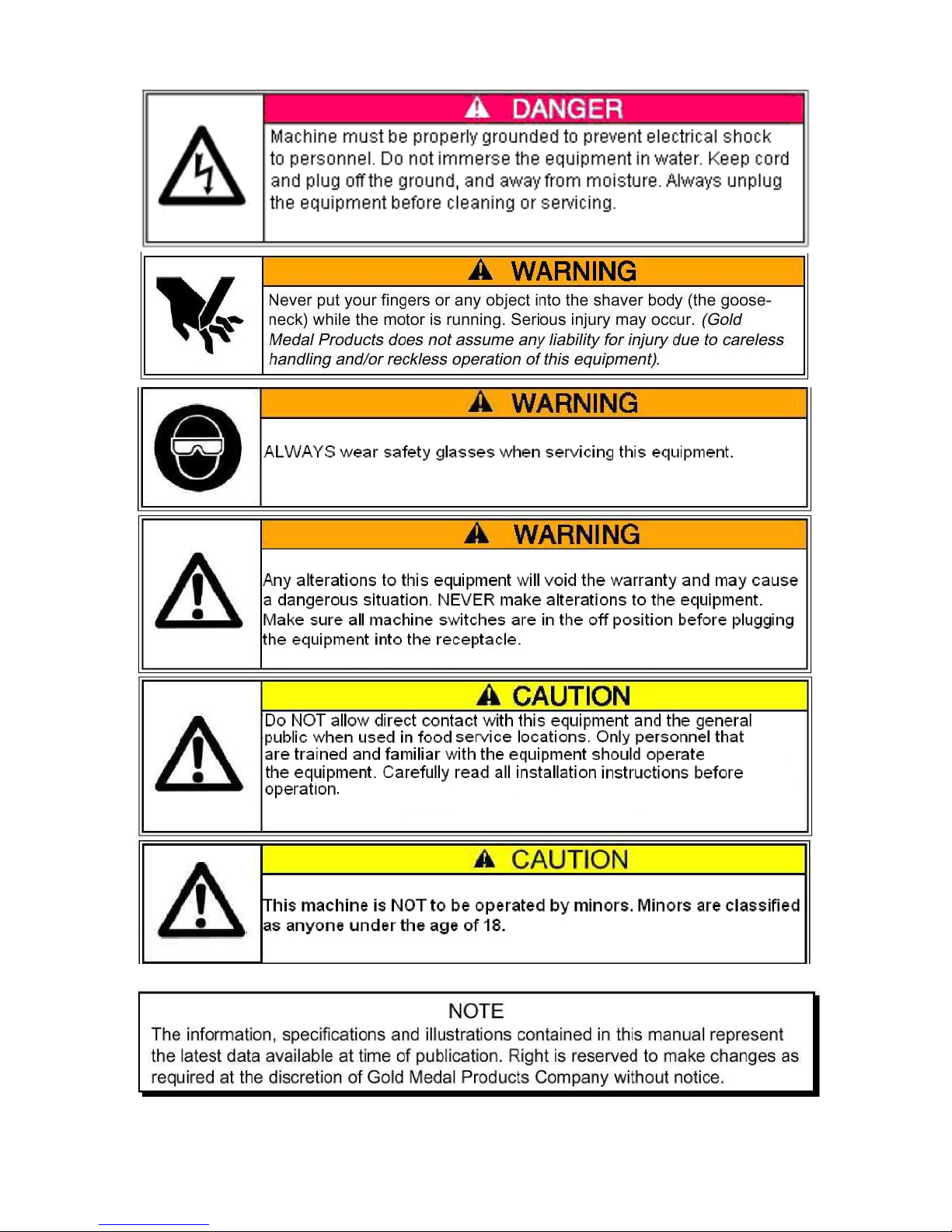
SAFETY PRECAUTIONS
Page 3
ShaveMaster II
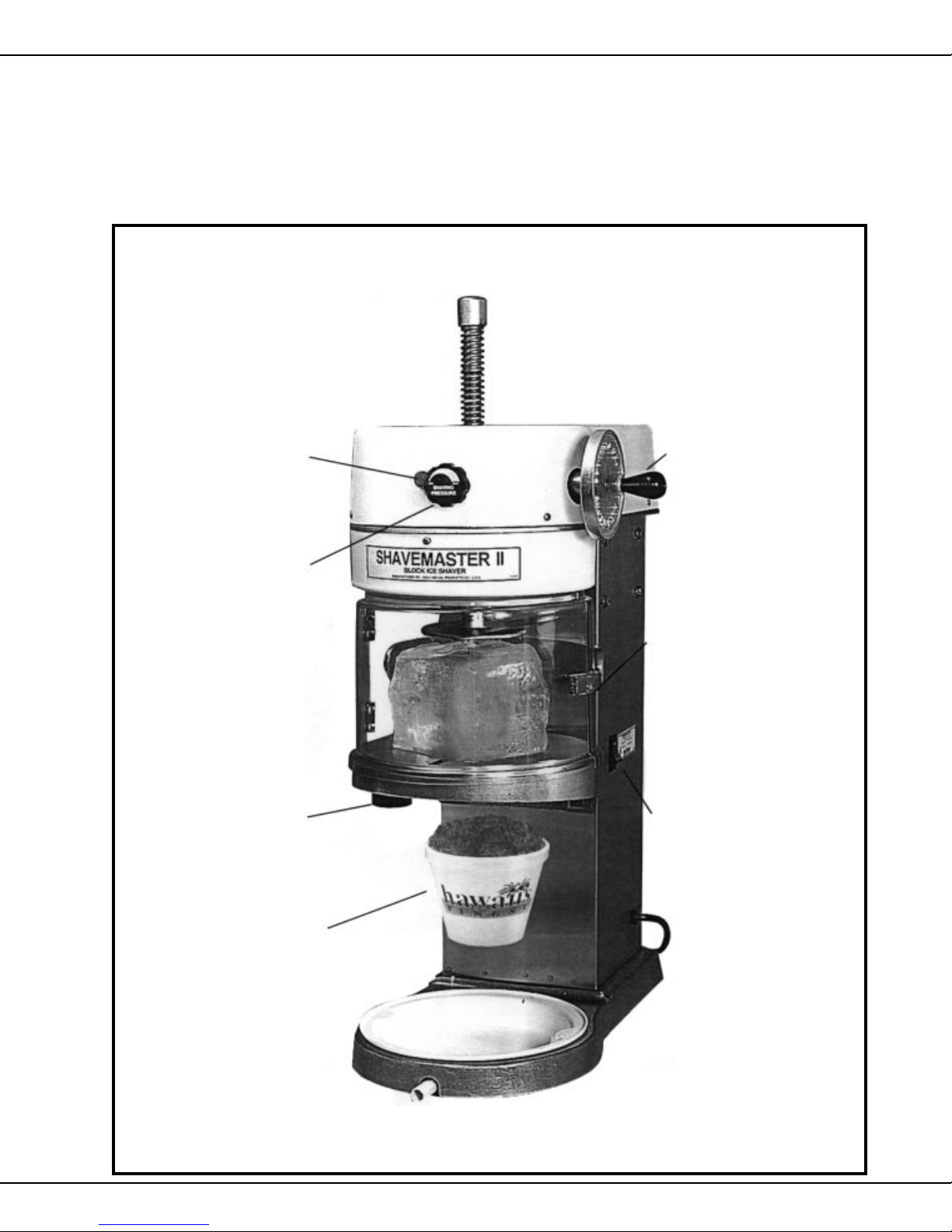
HOW TO OPERATE THE SHAVEMASTER II
MAIN SHAFT
Rotates when motor is "ON".
Keep fingers away.
Step 1: LOCKING KNOB
Pull and turn to "unlock"
main shaft. Be sure the
motor is "OFF".
Step 4: SHA VING
PRESSURE KNOB
Rotate clockwise "finger
tight" to put pressure on
the ice block.
Step 5: BLADE FINENESS
KNOB
Rotate to minimum
shaving height for
fine snow.
Step 2: HAND WHEEL
for main shaft.
Rotate to maintain
height.
Step 3: ICE COMP ARTMENT
FRONT DOOR LA TC H
Open door latch and place
block of ice in center, then
close and relatch door.
Step 7: ON–OFF SWITCH
Now start shaving
process here or by using
#1008 Foot Switch.
Step 6: HAW AIIAN ICE CUP
Hold Hawaiian Ice Cup an
inch or two below shaved
ice discharge area then
"shape" by hand. Always
wear food handler gloves.
1
MODEL #1005
Page 4

ShaveMaster II
SPECIFICATIONS
Dimensions: 28" High x 11" Wide x 20" Deep
Shipping Weight: 83 Lbs.
Electrical Requirement: 120 Volts, 60 Hz, 4.7 Amps, 1 Phase
Shaving Capacity: 4.4 – 5.5 Lbs./Min.
RPM: 250 rpm
Shaving Plate Diameter: 9 ¾"
Ice Block Capacity: 6" x 6" x 5 ½"
Accessories: Ice Mold with Lid, Ice Pick, Drain Tray, Food Approved Gear Lube
Optional Accessories: Foot Switch, Plastic Ice Pan
OPERATING INSTRUCTIONS
1. Make sure the machine is installed on a sturdy, level and waterproof surface.
2. Do not use the ice block directly from the freezer; the shaved ice will not be fluffy and can
cause excessive wear to your blade. Allow ice to soften ½ hour prior to shaving.
3. Pull and turn the main shaft locking knob so that you can raise the main shaft by turning the
handwheel. Once the ice block holder is raised upward, return the locking knob to the "LOCK"
position.
4. Open the front shield by releasing the safety latch and pulling forward.
5. Place a square or cylindrical ice block on the shaving platter, centering the block.
6. Place the locking knob to the free position and lower the main shaft by turning the hand wheel
until the spikes are imbedded in the ice.
7. Close the front shield (make sure the main power switch is turned "OFF") and reattach the
safety latch, locking the front and rear shields together.
8. Turn the Shaving Pressure Knob clockwise until it comes to a stop.
9. Turn "ON" the main power switch. The motor will not run if the front shield is open or not
properly closed.
10. Slowly turn the knob, located below the shaving platter, until you get the fineness of shaved
ice you desire.
SHAVING PRESSURE KNOB (located on front of machine)
1. This knob adjusts the amount of pressure which is applied downward onto the block of ice.
Turning the knob clockwise will increase the amount of shaved ice produced and will vary
the texture from very fine to coarse as the pressure is being applied.
2. When you need to raise and lower the main shaft, release the pressure by turning the
knob counterclockwise.
SHAVING TEXTURE KNOB (located on the underside of the blade platter)
1. Lower the shaver blade before adding the block of ice to the shaving platter. If the blade is
too high it could accidentally release the block out of the holder.
2. For coarse shaved ice, turn the knob clockwise. For finer shaved ice, turn the knob
counterclockwise.
2
MODEL #1005
Page 5

ShaveMaster II
ICE BLOCK FREEZING SUGGESTIONS
1. Use Gold Medal's plastic Ice Mold with Lid (Part No. 1085) to freeze blocks of ice.
2. Fill the container with cool tap water to a ½" from the top rim of the container.
3. Firmly press the lid onto the container until the lid snaps shut.
4. Set your frezer to a temperature range of 10-15º F. Fill your freezer with as many ice
molds as possible by stacking one on another. This will slow down the freezing process
and prevent cracking.
5. Let the water freeze completely for approximately 24-30 hours for best shaving results.
6. After the water has frozen, remove the block from the plastic container and place it into
Gold Medal clear bags (Part No. 3064) so you can use the ice mold container to freeze
more ice.
CLEANING INSTRUCTIONS
Wipe the exterior of the machine with a soft cloth that has been dipped into a mixture of mild dish
detergent and warm water. Remove excess water or soap spots with a soft cloth.
CLEANING THE INTERIOR OF THE SHAVING CHAMBER
1. Open the front shield of the shaving chamber and remove the shield by lifting it upward.
2. Raise the main shaft by rotating the handwheel. Turn and pull the locking knob until the main
shaft is held in the raised position.
3. Remove the (2) wing bolts on the underside of the shaving platter. Raise the shaving platter
and remove it from its holder.
4. Dismantle the blade assembly by unscrewing the (2) blade fastening screws which will
allow you to remove the blade and blade holder.
5. Remove the shaving texture knob from the threaded shaft.
6. Unscrew the (2) screws fastening the blade assembly to the shaving platter and remove the
remaining parts.
7. Dismantle all of the blade assembly parts. Wash the parts in a mild detergent and water
solution. Towel dry all of the items after rinsing off the soap.
8. Reassemble the unit in reverse order.
3
MODEL #1005
Page 6

ShaveMaster II
MAINTENANCE INSTRUCTIONS
THE FOLLOWING SECTIONS OF THIS MANUAL ARE INTENDED ONLY FOR QUALIFIED SERVICE PERSONNEL WHO
ARE FAMILIAR WITH ELECTRICAL EQUIPMENT. THESE ARE
NOT INTENDED FOR THE OPERATOR.
Adequate eye protection must be used when servicing this
equipment to prevent the possibility of injury.
Do NOT immerse the equipment in water.
Unplug your machine before servicing.
OILING THE MAIN DRIVE SHAFT AND CRANK
1. The main shaft must be kept lubricated at all times with Gold Medal food approved Gear
Lube (Part No. 1110). Do NOT use vegetable oil for lubrication; as the oil hardens, it will
prevent the main shaft from rotating.
2. Completely raise the main shaft and apply the supplied tube of food approved gear lube to
the teeth of the shaft. Apply oil to the center of the shaft with one small pass.
3. To oil the crank, remove the plastic dome and oil through the two small oiling holes located
on the top section of the casting. This will allow the handwheel shaft to rotate easily.
REPLACING WORN SHAVER BLADE
1. Remove the (2) wing bolts fastening the shaving platter to the mount casting. Remove the
platter from the mount casting and place it on a clean, level surface, flat side down.
2. Loosen the two screws fastening the shaver blade to the blade holder until the blade slips
out; remove the blade.
3. Turn the blade height adjustment knob so that the blade holder is in the lowest position.
Turn the knob back one full turn so the blade will go below the surface when completely
lowered.
4. Install new or re-sharpened blade exactly the same direction it was removed.
5. Blade should be installed with an even amount of space between the blade and groove.
6. Firmly tighten the two screws holding the clamp to the blade.
7. Place the blade platter back on the mount casting with the blade facing frontward.
8. Replace the (2) wing bolts, tighten firmly.
4
MODEL #1005
Page 7

ShaveMaster II
ASSEMBLING THE BLADE COMPONENTS AFTER CLEANING OR,
ADJUSTING BLADE IF MACHINE DOES NOT SHAVE.
1. Remove the (2) ¼-20 Thumb Screws from the underside of the Shaving Platter.
2. Remove the Shaving Platter from Support Casting and place it on a smooth flat surface
preferably a table or counter top.
3. Turn the “Blade Adjustment” knob clockwise until the knob is fully tightened.
4. Turn the knob back counter-clockwise a ½ revolution.
5. With a screwdriver, loosen the (4) ¼-20 slotted/knurled screws holding the Blade Clamp
and Shaving Base.
6. Let the Shaving Blade rest on your table or counter as you adjust it for straightness.
7. Before you tighten the (2) ¼-20 slotted/knurled screws which fastens the Shaving Base to
the Shaving Platter, make sure that the gap between the blade and rectangular slot in the
Platter is approximately 1/8” the entire length of the blade.
8. Firmly tighten the (2) screws for the shaving Base.
9. Before you tighten the Blade Clamp screws, make sure that the Blade is touching the table
top and is straight in the rectangular slot. Tighten the (2) screws with your screw driver.
10. Make sure all screws are securely tightened before placing it back on the machine.
11. Place the Shaving Platter back on the Support Casting, replacing the two thumb screws.
Exploded View
Maintain even blade spacing. Assemble on flat surface.
The blade is
extremely
sharp!
Note orientation of blade prior to installation.
5
MODEL #1005
Page 8

PROBLEMS CAUSES SOLUTIONS
Main shaft fails to turn with main
power switch on.
TROUBLESHOOTING
Cord not properly plugged in.
Broken power cord.
Motor drive belt broken. Replace worn belt.
Front shield is open. Close front shield and latch.
ShaveMaster II
Plug cord into properly.
Replace power cord.
Lower blade with adjustment
knob.
Remove shaving platter and
readjust blade height evenly.
Lower clamp down with force.
Turn ice block over to flat side.
Turn the shaving pressure knob
clockwise.
Turn the shaving pressure knob
counterclockwise.
Ease the tension by turning the
shaving pressure knob
counterclockwise.
Ice block jumps out of clamp.
Shaved ice is too fine.
Shaved ice is too coarse.
Very hard to raise and lower the main
drive shaft with the handwheel.
Blade is raised too high.
Blade is higher near center
than outside of platter.
Spikes not firmly embedded in
the ice block.
Shaver blade is too low. Raise blade into ice with knob.
Tension adjustment of brake
is too weak.
Shaver blade is too high. Lower blade from ice with knob.
Tension adjustment of brake
is too strong.
Blade is dull. Replace or sharpen blade.
Brake tension is too tight.
ORDERING SPARE PARTS
1.Identify the desired part by checking it against the photos, illustrations, and/or the parts list.
2.When ordering, please include part number, part name, and quantity desired.
3.Please include your model name and machine serial number (located on the machine
nameplate) with your order.
4.Address all parts orders to:
Parts Department
Gold Medal Products Co.
10700 Medallion Drive
Cincinnati, Ohio 45241-4807
or, place orders at:
(513) 769-7676
Fax: (513) 769-8500
E-mail: goldme19@eos.net
6
MODEL #1005
Page 9

SHAVEMASTER II ASSEMBLY
ShaveMaster II
7
MODEL #1005
Page 10

PARTS LIST – SHAVEMASTER II ASSEMBLY
Item No. Part No. Description
1 12115 Rocker Switch, SPST
2 12302 Bellow, Gear Protector
3 12305 Upper Mount Casting
4 12306 Gear Housing
5 12308 Brake Shoe
6 12309 Blade Platter
7 12310 Blade Holder
8 12399 Pivot Bracket, Blade
9 12312 Blade Mount
10 12313 Shield Holder, Casting
11 12314 Base Casting
12 12315 Platter Mount, Casting
13 12317 Drain Pan, Plastic
14 12318 Shaft, Brake Adjustment
15 12320 Cap, Main Shaft
16 12321 Main Drive Shaft
17 12322 Ice Block Clamp
18 12324 Cover, Safety Switch
19 12325 Top Cover, Dome
20 12326 Shield, Front, Assembly
21 12327 Shield, Rear, Assembly
22 12328 Shaver Blade
23 12332 Shaft, Blade Pivot
24 12333 Knob, Blade Pivot
25 12334 Dome Support Bracket
26 12335 Motor Mount Plate
27 12339 Sheave, Small
28 12340 V-belt
29 12342 Retainer Plate, Bellows
30 12343 Rear Cover
31 12345 Spring, Brake Tension
32 12347 Spring, Blade Pivot
33 12348 Knob, Shaving
34 12349 Hand Wheel
35 12350 Clamp, Bellows (2)
ShaveMaster II
8
MODEL #1005
Page 11

ShaveMaster II
PARTS LIST – SHAVEMASTER II ASSEMBLY (continued
Item No. Part No. Description
36 12353 Tube Spacer
37 12357 Worm Gear Assembly
12329 Worm Gear
38 12359 Gear Lock Assembly
39 12360 Switch, Door Safety
40 12361 Bracket, Safety Switch
41 12364 Knob, Brake Adjustment
42 12365 Hinge Mt, Plate Assembly
43 12368 Knob, Hand Wheel
44 12369 Tube, Hand Wheel Pivot
45 12370 Decal, Front Cover
46 12371 Large Sheave Assembly
47 12377 Main Wrapper, Stainless Steel
48 12390 Decal, Warning
49 12391 Drain Hose
50 12394 Retainer Assembly
51 22038 Lead-in cord
52 39022 Drive Motor, 120V
53 40488 Foot, Plastic
54 49138 Hinge, Left Female
55 49141 Hinge, Left Male
56 12380 Thumb Screw
57 12319 Knob, Shaft Lock
58 12425 Bearing Holder Assembly
1110 Tube Petrogel
22020 Ice Pick
1085 Ice Mold with Lid
12430 Decal, Rear Cover
)
9
MODEL #1005
Page 12

ELECTRICAL SCHEMATIC
ShaveMaster II
10
MODEL #1005
Page 13

WARRANTY
WE WARRANT to the original purchaser the Gold Medal equipment sold by us to
be free from defects in material or workmanship under normal use and service. Our
obligation under this warranty shall be limited to the repair or replacement of any
defective part for a period of six (6) months from the date of sale to the Original
Purchaser with regard to labor and two (2) years with regard to parts and does not
cover damage to the equipment caused by accident, alteration, improper use, voltage, abuse, or failure to follow instructions.
THIS WARRANTY IS IN LIEU OF ALL OTHER WARRANTIES EXPRESSED
OR IMPLIED, AND OF ALL OTHER OBLIGA TIONS OR LIABILITIES ON OUR
PART, INCLUDING THE IMPLIED WARRANTY OF MERCHANTIBILITY.
THERE ARE NO WARRANTIES WHICH EXTEND BEYOND THE DESCRIPTION ON THE F ACE HEREOF. W e neither assume, nor authorize any other person
to assume for us, any other obligation or liability in connection with the sale of said
GOLD MEDAL equipment or any part thereof.
The term “Original Purchaser” as used in this warranty shall be deemed to mean that
person, firm, association, or corporation who was billed by the GOLD MEDAL
PRODUCTS COMPANY, or their authorized distributor for the equipment.
THIS WARRANTY HAS NO EFFECT AND IS VOID UNLESS THE ORIGINAL
PURCHASER FIRST CALLS GOLD MEDAL PRODUCTS COMP ANY AT 1-800428-2676 TO DISCUSS WITH OUR SERVICE REPRESENT ATIVE THE EQUIPMENT PROBLEM, AND, IF NECESSARY, FOR INSTRUCTIONS CONCERNING THE REPAIR OR REPLACEMENT OF P ARTS.
NOTE: This equipment is manufactured and sold for commercial use only.
GOLD MEDAL PRODUCTS COMPANY
10700 Medallion Drive
Cincinnati, OH 45241-4807 USA
 Loading...