

Page 1
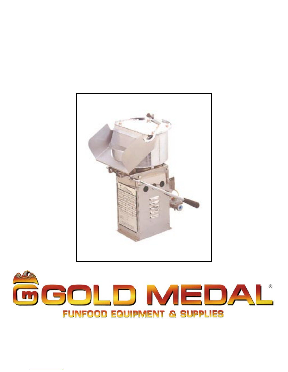
Mighty–Mite
a
Instruction Manual
Part No. 74570
Revised June 1996
Model #2035BG (Bottle Gas
Model #2035DC (DC Motor, Bottle Gas
Model #2035NG (Natural Gas
)
)
)
Cincinnati, OH 45214-2089 USA
Page 2
GAS SAFETY PRECAUTIONS
a
Page 3
Mighty–Mite
a
This instruction booklet is very thorough and complete. Please take the time to read this entire
booklet before attemting to operate the appliance.
Your Mighty-Mite Commercial Popper is the finest 14 Oz. gas popper ever built. The special alloy
steel kettle is extra heavy to prevent burnouts or warping, and is made from excellent heat conducting steel. Your Mighty-Mite has an extra heavy duty motor equipped with an extra fan and air
tunnel to direct cooling over the motor at all times allowing the motor to run cooler under heavier
popping conditions.
UNPACKING AND ASSEMBLY
After unpacking your Mighty-Mite, set it on a counter where you intend to use it and remove all
the tape. Make sure clearances around and overhead the appliance comply with the marking
on the data plate for the location you have selected. Attach the counterweight assembly as
per Drawing D-4957.
INSTALLATION
When installing your new Mighty-Mite Commercial Gas Popper, you must conform with local
codes, or in the absence of local codes, with the National Fuel Gas Code, ANSI Z223.1-1980.
Gas is safe when used properly, but can be very dangerous
when used improperly. We suggest that installation be carefully
made by only a qualified service person. Gas companies have
competent service people to provide safe installation.
When selecting a location for your new Mighty-Mite, pay close attention to the installation clearances. The MINIMUM clearance for the sides is 6 inches; the MINIMUM top, back and frontal
clearance is 30 inches. This unit is certified for use on combustible surfaces.
The appliance and its individual shutoff valve must be disconnected from the gas supply piping
during pressure testing of that system at pressures greater than 0.5 psig (3.45 kPa).
During any pressure testing of the gas supply piping system at pressures equal to or less than 0.5
psig (3.45 kPa), the appliance must be isolated from the gas supply piping system by closing its
individual manual shutoff valve.
This unit must be grounded in accordance with local codes; or, in the absence of local codes,
withthe National Electric Code - ANSI/NFPA No. 70-1981. Secure grounded wire to ground lug
provided inside the cabinet wiring junction box.
When wiring your new Mighty-Mite, refer to the wiring diagram located inside of the cabinet and in
this Instruction Manual (Drawing No. A-74500 for AC Model; Drawing No. A-74511 for DC Model).
1
ALL MODELS #2035
Page 4
Mighty–Mite
a
After installation all gas connections must be checked for leaks with a soap solution. When gas
connection is complete, wire the unit to the power source which will carry the current specified on
the unit's data plate.
Do NOT use a match or flame to check for leaks – you may
cause a fire or explosion!
TYPES OF GAS
The nameplate is marked at the factory to indicate the type of gas the appliance uses: either,
LP or propane for Liquified Petroleum Gas, or NAT or NG for Natural Gas. If necessary the
unit can be altered to change fuels, but we suggest a qualified service person do the work.
Please have your service person refer to the
Maintenance and Repair
section of this manual.
ALTITUDE RANGE
The factory has sized the burner orifices for an elevation up to 2000 feet above sea level. For
high altitude operation, please contact Gold Medal Engineering for the proper orifice size.
GAS PRESSURE
We have determined that optimum popping results occur when the gas pressure is adequate.
For LP gas, we recommend a pressure setting of 10 inches water column (6 oz. per square
inch); and, for Natural Gas, 4 inches water column (2 oz. per square inch). The pressure is
measured at the appliance while the main burner is ignited. A pressure regulator is supplied to
deliver the optimum pressure for both types of gas when the unit is changed from the original
factory specification. Follow the instructions in the
gas requirements are maintained by properly sized piping. Be sure the piping is properly sized
to supply the needed pressure.
Maintenance and Repair
section. Adequate
2
ALL MODELS #2035
Page 5
Mighty–Mite
a
LIGHTING AND SHUTDOWN INSTRUCTIONS
1. Turn the handle of the gas safety valve to the "PILOT" position.
2. Push down the red reset button, depress the spark igniter and repeat until the pilot lights.
Hold the red reset button for about 30-45 seconds or until the pilot remains burning when
the button is released.
3. Turn the main handle to the "ON" position. The main burner should now ignite from the
pilot burner.
4. If you want to turn off both the pilot and the main burner, pull lock on safety and turn to the
"OFF" position.
If pilot is turned out, a five minute shut down period is required
before attempting to relight.
AIR ADJUSTMENT ON BURNER
After your main burner has been lit according to the directions above, you might have to make
some air adjustment in order to get the best flame. The Air Adjustment Cap should be turned
to give more or less air. A blue flame is desired for optimum heat.
TO POP POPCORN
Turn the main burner on and put oil in the kettle. You can let oil heat slightly before adding the
popcorn and salt. We recommend 14 ounces of popcorn, 4 ½ ounces of high quality coconut oil,
and Flavacol salt to give the best results. A good measure of oil and Flavacol is the secret to top
quality popcorn; popcorn that brings you more repeated sales. If you are in a commercial
pre-pop operation, this is even more important; good quality pre-pop commands a higher price. To
your customer, it is well worth the slight extra price.
Yes, you can put more corn into the kettle, but this will lenghten the popping cycle and your
overall production will decrease. You can make smaller batches, if necessary, but always use a
corn to oil ration of 3:1. When using a smaller batch you might turn the burner down slightly to
prevent it form getting too hot.
IF THE FLAME GOES OUT
A 5 minute shutdown period is required before attemting to relight.
1. Check to see if you are out of gas.
2. Check to see if the thermocouple is in the proper position.
At no time during a power failure is there to be an attempt to operate
this unit. In the case that a power failure occurs during operation, the
gas supply is to be turned OFF until power failure has subsided. Then,
and only then, should a relight attempt be made per the
Shutdown Instructions
Lighting and
.
3
ALL MODELS #2035
Page 6
MAINTENANCE INSTRUCTIONS
a
THE FOLLOWING SECTIONS OF THIS MANUAL ARE INTENDED ONLY FOR QUALIFIED SERVICE PERSONNEL WHO
ARE FAMILIAR WITH ELECTRICAL EQUIPMENT. THESE ARE
NOT INTENDED FOR THE OPERATOR.
Adequate eye protection must be used when servicing this
equipment to prevent the possibility of injury.
Mighty–Mite
Do NOT immerse the equipment in water.
Unplug your machine before servicing.
LUBRICATION REQUIREMENTS
DRIVE MOTOR
This is a sealed bearing type motor and requires no lubrication.
GAS CONVERSION
1.Disconnect the power supply at the fuse box or breaker.
2.Turn off the gas supply.
3.Refer to drawing number D-5019.
4.Place the kettle in the dump position. Remove the retainer screws. Remove the burner
(Part No. 74558) to expose the burner orifice hood. Replace the main burner hood with the
appropriate part number for the intended type of gas.
A.Part # 74629 (#61) for LP gas.
B.Part # 74630 (#53) for Natural Gas.
5.Replace the pilot burner orifice with the appropriate part number for the intended type of
gas.
Pilot Burner Part No. 74028
A.Part No. 74029 (.011 Dia. Holes) for “LP” Gas.
6.Remove the hex cap on the pressure regulator and position the appropriate end of the red
plug down. “LP” for Liquefied Petroleum Gas, and “NAT” for Natural Gas. Replace the
hex cap. (Instructions continued next page.)
B.Part No. 74531 (.018 Dia. Holes) for Natural Gas. (“NAT”)
Pilot Burner Part No. 57031
A.Part No. 74029 (.011 Dia. Holes) for "LP” Gas.
B.Part No. 74030 (.023 Dia. Holes) for Natural Gas. (“NAT”)
4
ALL MODELS #2035
Page 7

Mighty–Mite
a
7.CAUTION: Orifice hoods and spuds must be screwed tight when LP gas is used.
8.Turn on gas supply and leak test all connections with a soap solution.
9.Turn on main power.
ORDERING SPARE PARTS
1.Identify the desired part by checking it against the photos, illustrations, and/or the parts list.
2.When ordering, please include part number, part name, and quantity desired.
3.Please include your model name and machine serial number (located on the machine
nameplate) with your order.
4.Address all parts orders to:
Parts Department
Gold Medal Products Co.
10700 Medallion Drive
Cincinnati, Ohio 45241-4807
or, place orders at:
(513) 769-7676
Fax: (513) 769-8500
E-mail: goldme19@eos.net
5
ALL MODELS #2035
Page 8

BASO VALVE INFORMATION
a
Mighty–Mite
6
ALL MODELS #2035
Page 9

Mighty–Mite
a
BASO VALVE INFORMATION (continued
)
7
ALL MODELS #2035
Page 10

KETTLE CROSS SECTION ASSEMBLY
a
Mighty–Mite
8
ALL MODELS #2035
Page 11

Mighty–Mite
a
PARTS LIST – KETTLE CROSS SECTION ASSEMBLY
Item No. Part No. Description
1-1 74571 Set Screw, #8-32 x 5/8"
1-2 47120 Knob, Lid Lift
1-3 82108 Counter Weight, with #8-32 Tap
1-4 74529 Counter Weight Bar, 14 Ounce
1-5 74147 Screw, #8-32 x ½" Rd. Hd. Ph.
1-6 74146 Hex Nut, #8-32 ESLOK
1-7 74545 Lid Assembly, Welded
1-8 74546 Dump Chute
1-9 74504 Kettle without Agitator and Lid
1-10 74102 Set Collar, Reamed
1-11 41139 Dump Handle, Plastic
1-12 74512 Drive Shaft Assembly
1-13 74513 Kettle Bearing Hub Assembly
1-14 74553 Nut, Hex Jam ¾-16
1-15 74555 Washer, Copper ¾" I.D.
1-16 74554 Thrust Washer, Bronze
1-17 86540 Cotter Pin
1-18 74527 Agitator Assembly
1-19 74088 Seal, Lid Hold Down Screw
1-20 74117 Flat Washer, #8
1-21 74001 Screw, Lid Hold Down
1-22 74574 Wing Nut, #10-24 Nylon Insert
1-23 74520 Hex Head Bolt, ¼-20 x ¾"
1-24 47751 Set Screw, ¼-20 x
3
/16"
ADDITIONAL PARTS for Mighty–Mite (Items not shown)
47145 A Scoop
47147 Measure, One Cup
47148 Measure, 14 Ounce
47660 Gold Towel
47679 Measure, 14,7cc
74505 Kettle Assembly, Complete
74552 Spring Pin,
47010 Label, Safe Operating Instructions
74510 Shaft, Extension
74631 Label, Do Not Leave Burner
74570 Parts Manual, Mighty-Mite
74575 Tag, Warning LP Gas
ADDITIONAL PARTS for Model #2035DC (Items not shown)
74636 Fuseholder, Mighty-Mite
74637 Fuse, 2.5 Amp
74640 Mighty-Mite Cabinet Assembly
1
/8" x ¾"
9
ALL MODELS #2035
Page 12

CABINET ASSEMBLY
a
Mighty–Mite
10
ALL MODELS #2035
Page 13

PARTS LIST – CABINET ASSEMBLY
a
Item No. Part No. Description
2-1 74029 Pilot Orifice .011 LP (Used with P/N 74028)
2-1a 74029 Pilot Orifice .011 LP (Used with P/N 57031)
2-2 74531 Pilot Orifice .018 NAT (Used with P/N 74028)
2-2a 74030 Pilot Orifice .023 NAT (Used with P/N 57031)
2-3 74028 Pilot Burner
2-3a 57031 Pilot Burner
2-4 74629 Hood, Orifice #61 LP
2-5 74630 Hood, Orifice #53 NAT
2-6 74658 Fitting, Orifice Brass
2-7 74562 Brass Pipe Plug,
2-8 74560 T-fitting
2-9 74536 Mounting Bracket Regulator
2-10 74559
2-11 74027 Gas Safety Valve
2-12 57030 Thermocouple
2-13 74561 ¼" Alum. Tube, 18" Long
2-14 74036
2-15 74115 Pressure Regulator, NG & LP
2-16 74120 Label, Lighting Instruction
2-17 89045 Strain Relief, T & B #3302
2-18 74543 Mighty-Mite Pedestal Weld
2-19 74116 Label, Ground
2-20 74519 Front Cover Junction Box
2-21 47236 Bushing, Snap #SB-500-6
2-22 74538 Front Cover Plate
2-24a 74500 Wiring Diagram, 120 & 230 Volt
2-24b 74511 Wiring Diagram, 12 Volt
2-25 74119 Label, Warning Disc. Power
2-26 74551 Extension Shaft Assembly
2-27 74542 Mount Plate, Burner
2-28 74532 Dump Bar Mounting Bracket, L. Side
2-29 74535 Dump Bar Mounting Bracket, R. Side
2-30 74558 Burner, Mighty-Mite
2-31 74515 Shield, Pilot Burner
2-32 74520 Hex Head Bolt, ¼-20 x ¾"
2-33 74141 Screw, #8-32 x
2-34 74143 Hex Nut, #10-32
2-35 74145 Screw, #10-32 x 1 ½" Rd. Hd. Ph.
2-36 42302 Washer, #10 Internal Tooth
2-37 74147 Screw, #8-32 x ½" Rd. Hd. Ph.
2-38 74150 Washer, #8 Internal Tooth
2-39 74149 Hex Nut, #8-32
2-40 74133 Hex Nut, ¼-20
2-41 42153 Set Screw, ¼-20 x 1 ½"
2-42 74136 Hex Head Bolt, #10-24 x ¾"
3
/8" Close Nipple
3
/8" Brass Street Ell
3
1
/8" NPT
/8" Rd. Hd. Ph.
Mighty–Mite
11
ALL MODELS #2035
Page 14

Mighty–Mite
a
PARTS LIST – CABINET ASSEMBLY (continued
Item No. Part No. Description
2-43 74530 Shield, Heat
2-45 46566 Spring Pin,
2-46 42070 Set Screw #10-24 x ½"
2-47 47038 Kettle Motor, 120V 60 Cycle
2-48 47028 Kettle Motor, 230V 50 Cycle
2-49 74576 12 Volt DC Motor
2-50 47202 Switch, Motor 120 & 230 Volt
2-51 47201 Switch, On-Off 12 VDC
2-52 74147 Screw, #8-32 x ½" Rd. Hd. Ph.
2-53 74153 Screw, #8-32 x 1" Hex Hd.
2-54 74633 Ground Lug
1
/8" x 7/8"
)
12
ALL MODELS #2035
Page 15

ELECTRICAL SCHEMATIC
a
Mighty–Mite
13
ALL MODELS #2035
Page 16

Mighty–Mite
a
ELECTRICAL SCHEMATIC – MODEL #2035DC ONLY
14
ALL MODELS #2035
Page 17

WARRANTY
WE WARRANT to the original purchaser the Gold Medal equipment sold by us to
be free from defects in material or workmanship under normal use and service. Our
obligation under this warranty shall be limited to the repair or replacement of any
defective part for a period of six (6) months from the date of sale to the Original
Purchaser with regard to labor and two (2) years with regard to parts and does not
cover damage to the equipment caused by accident, alteration, improper use, voltage,
abuse, or failure to follow instructions.
THIS WARRANTY IS IN LIEU OF ALL OTHER WARRAN TIES EXPRESSED
OR IMPLIED, AND OF ALL OTHER OBLIGATIONS OR LIABILITIES ON OUR
PART, INCLUDING THE IMPLIED WARRANTY OF MERCHANTIBILITY.
THERE ARE NO WARRANTIES WHICH EXTEND BEYOND THE DESCRIPTION
ON THE FACE HEREOF. We neither assume, nor authorize any other person
to assume for us, any other obligation or liability in connection with the sale of said
GOLD MEDAL equipment or any part thereof.
The term “Original Purchaser” as used in this warranty shall be deemed to mean that
person, firm, association, or corporation who was billed by the GOLD MEDAL
PRODUCTS COMPANY, or their authorized distributor for the equipment.
THIS WARRANTY HAS NO EFFECT AND IS VOID UNLESS THE ORIGINAL
PURCHASER FIRST CALLS GOLD MEDAL PRODUCTS COMPANY AT 1-800543-0862 TO DISCUSS WITH OUR SERVICE REPRESENTATIVE THE
EQUIPMENT PROBLEM, AND, IF NECESSARY, FOR INSTRUCTIONS
CONCERNING THE REPAIR OR REPLACEMENT OF PARTS.
GOLD MEDAL PRODUCTS COMPANY
10700 Medallion Drive
Cincinnati, Ohio 45241-4807 USA
www.gmpopcorn.com
Phone: 1-800-543-0862
Fax: 1-800-542-1496
© The text, descriptions, graphics and other material in this publication are the proprietary
and exclusive property of Gold Medal Products Company and shall not be used, copied,
reproduced, reprinted or published in any fashion, including website display, without its
express written consent.
 Loading...