

Page 1
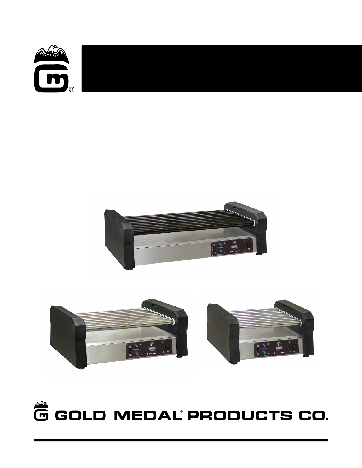
Hot Diggity® Pro Series
One Touch Control
Model Series: 8550, 8551, 8552 (010 and 011)
Instruction Manual
Model 8552-00-011
Model 8551-00-010
Model 8550-00-010
© 2018 Gold Medal Products Co.
10700 Medallion Drive, Cincinnati, Ohio 45241-4807 USA
Part No. 110230
Page 2

Hot Diggity Pro Series
One Touch Control Model Series: 8550, 8551, 8552 (010 and 011)
Table of Contents
SAFETY PRECAUTIONS ............................................................................................................................. 3
INSTALLATION INSTRUCTIONS .............................................................................................................. 5
Inspection of Shipment ..............................................................................................................................................5
Manual ................................................................................................................................................................................5
Model Description ........................................................................................................................................................5
Items Included with this Unit..................................................................................................................................5
Setup ...................................................................................................................................................................................5
Feet Spacer Installation .............................................................................................................................................6
Electrical Requirements ............................................................................................................................................7
Before You Plug In Machine .....................................................................................................................................7
OPERATING INSTRUCTIONS .................................................................................................................... 8
Controls and Their Functions .................................................................................................................................8
Operating Instructions ...............................................................................................................................................9
Programming the Digital Temperature Control ........................................................................ 10
One Touch Control .................................................................................................................................................... 10
Initial Setup Check of the Heating Profile ...................................................................................................... 11
Programming the Three Inputs .......................................................................................................................... 12
Care and Cleaning ............................................................................................................................... 13
MAINTENANCE INSTRUCTIONS ............................................................................................................ 14
ORDERING SPARE PARTS....................................................................................................................... 15
Cabinet Front View – Parts Breakdown .......................................................................................................... 16
Cabinet Rear/Bottom View – Parts Breakdown ......................................................................................... 18
Safety Labels................................................................................................................................................................. 20
Accessories.................................................................................................................................................................... 20
Wiring Diagram ................................................................................................................................... 21
WARRANTY................................................................................................................................................ 22
Page 2
gmpopcorn.com
Page 3
Hot Diggity Pro Series
DANGER
DANGER
WARNING
WARNING
WARNING
WARNING
One Touch Control Model Series: 8550, 8551, 8552 (010 and 011)
SAFETY PRECAUTIONS
Machine must be properly grounded to prevent electrical shock to personnel.
Failure to do so could result in serious injury, or death.
DO NOT immerse any part of this equipment in water.
DO NOT use excessive water when cleaning.
Keep cord and plug off the ground and away from moisture.
Always unplug the equipment before cleaning or servicing.
Make sure all machine switches are in the OFF position before plugging the
equipment into the receptacle.
Improper installation, adjustment, alteration, service, or maintenance can
cause property damage, injury, or death. Any alterations to this equipment
will void the warranty and may cause a dangerous condition. This appliance
is not intended to be operated by means of an external timer or separate
remote-control system. NEVER make alterations to this equipment. Read the
Installation, Operating, and Maintenance Instructions thoroughly before
installing, servicing, or operating this equipment.
008_051514
014_020416
To avoid burns, DO NOT touch heated surfaces.
DO NOT place or leave objects in contact with heated surfaces.
009_092414
ALWAYS wear safety glasses when servicing this equipment.
010_010914
No user serviceable parts inside. Refer servicing to qualified service
personnel.
011_051514
Read and understand operator’s manual and all other safety instructions
before using this equipment. To order copies of the operator’s manual go to
gmpopcorn.com or write to Gold Medal Products Co., 10700 Medallion Drive,
Cincinnati, OH 45241 USA 1-(800)-543-0862
022_060215
Page 3
gmpopcorn.com
Page 4
Hot Diggity Pro Series
WARNING
WARNING
One Touch Control Model Series: 8550, 8551, 8552 (010 and 011)
DO NOT allow direct contact of this equipment by the public when used in
food service locations. Only personnel trained and experienced in the
equipment operation may operate this equipment.
Carefully read all instructions before operation.
This machine is NOT to be operated by minors.
Note: Improvements are always being made to Gold Medal’s equipment. This information
may not be the latest available for your purposes. It is critical that you call Gold Medal’s
Technical Service Department at 1-800-543-0862 for any questions about your
machine operations, replacement parts, or any service questions. (Gold Medal
Products Co. does not assume any liability for injury due to careless handling and/or
reckless operation of this equipment.) General images may be used in manual for
reference only.
012_010914
007_010914
Page 4
gmpopcorn.com
Page 5
Hot Diggity Pro Series
Standoff Kit
(Spacers)
One Touch Control Model Series: 8550, 8551, 8552 (010 and 011)
INSTALLATION INSTRUCTIONS
Inspection of Shipment
After unpacking, check thoroughly for any damage which may have occurred in transit. Claims
should be filed immediately with the transportation company. The warranty does not cover
damage that occurs in transit, or damage caused by abuse, or consequential damage due to the
operation of this machine, since it is beyond our control (reference warranty in back of manual).
Manual
Read and understand the operator’s manual and all other safety instructions before using this
equipment. To order copies of the operator’s manual go to gmpopcorn.com or write to Gold
Medal Products Co., 10700 Medallion Drive, Cincinnati, OH 45241 USA 1-(800)-543-0862.
Model Description
The Hot Diggity Pro Series Roller Grills are equipped with a One Touch Digital Control.
8550-00-010: Compact Roller Grill with stainless steel rollers
8550-00-011: Compact Roller Grill with non-stick rollers
8551-00-010: Standard Roller Grill with stainless steel rollers
8551-00-011: Standard Roller Grill with non-stick rollers
8552-00-010: Large Roller Grill with stainless steel rollers
8552-00-011: Large Roller Grill with non-stick rollers
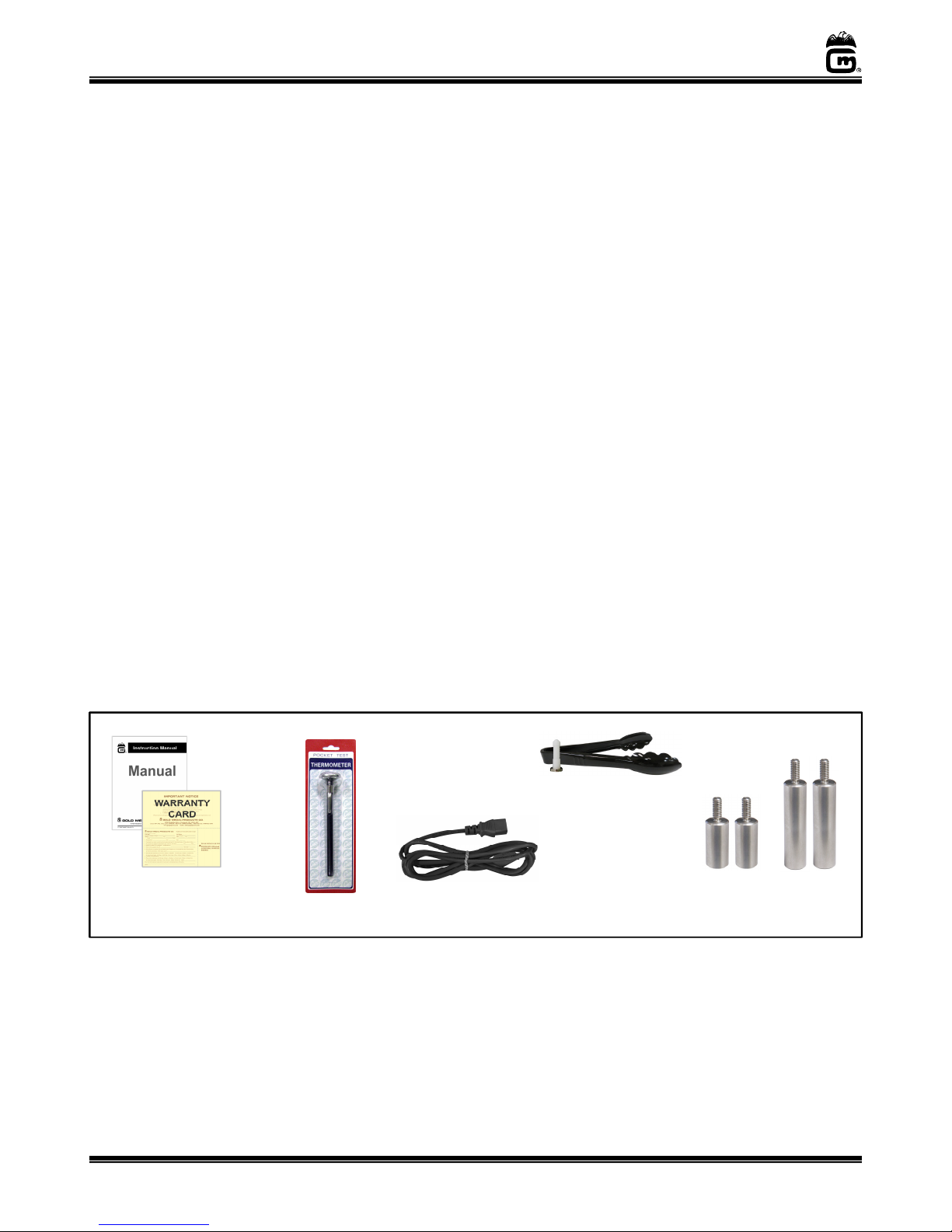
Items Included with this Unit
Instruction
Manual
Registration
Warranty Card
1 in. Dial
Thermometer
(PN 8000)
IEC Power Cord
(PN 102020)
9” Plastic Tongs
(PN 87092)
Tong Holder
(PN 69075)
(PN 114022)
Setup
1. This unit has been tested at the factory, remove all packaging and tape prior to operation.
2. Place unit on a sturdy, level base for use. There are 4 leveler feet on the bottom of the
cabinet, adjust as needed. This unit is also equipped with 2 sets of feet height spacers
which adjust the roller grill angle to approximately 4 degrees or 8 degrees slant, if
desired (reference Feet Spacer Installation section to install spacers).
Page 5
gmpopcorn.com
Page 6
Hot Diggity Pro Series
Step 2:
Carefully
set unit on
Step
4: Screw a foot into each of
overtighten.
One Touch Control Model Series: 8550, 8551, 8552 (010 and 011)
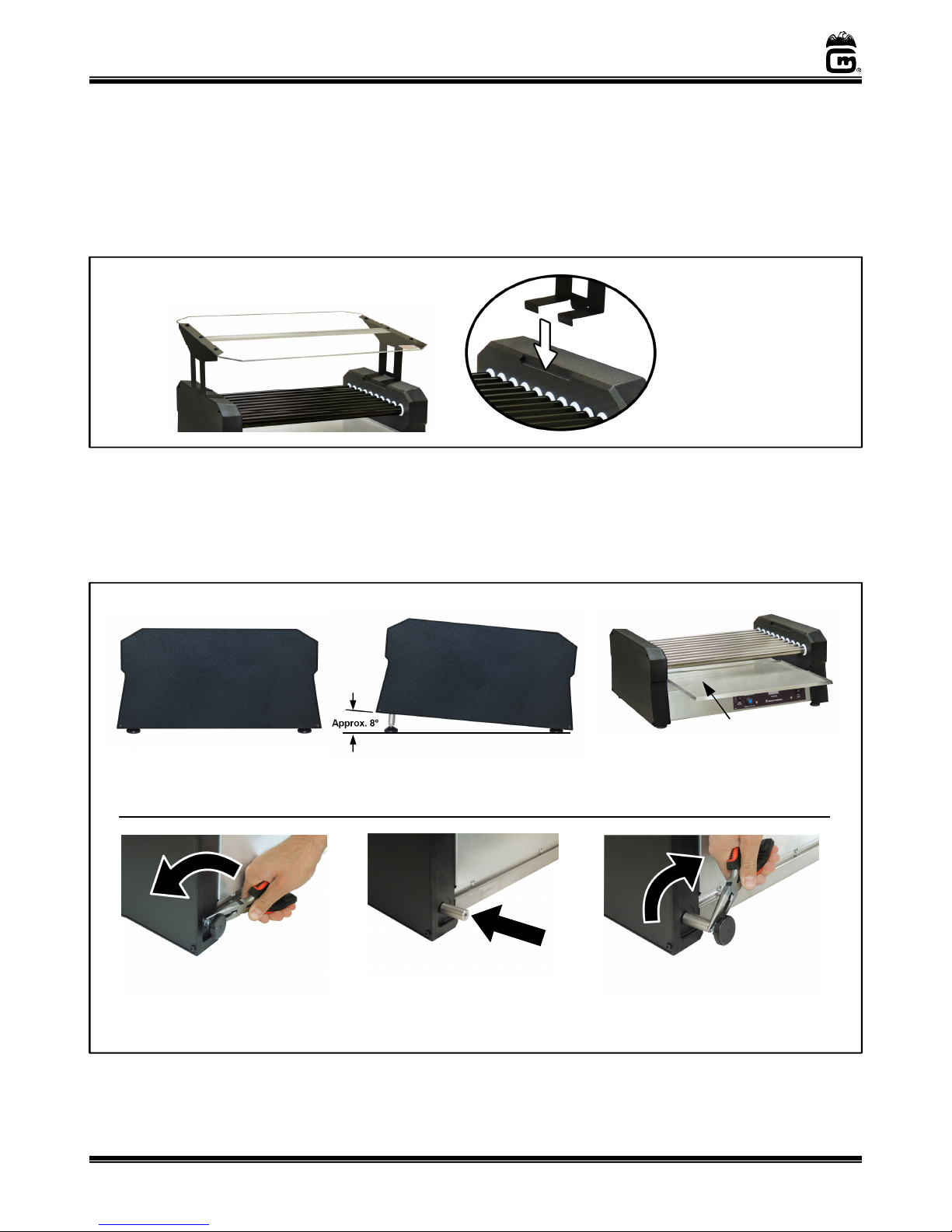
3. The Roller Grill is equipped with stand locators on each end of the unit for a Food Shield
option (sold separately), reference image below for mounting a Food Shield, if desired.
4.
Securely plug IEC Power Cord into unit. See Electrical Requirements section to plug
unit into power source for use.
5. After setup, the unit should be cleaned prior to use (see Care and Cleaning section).
Position Food Shield on Roller Grill
so it slants down towards customer.
Feet Spacer Installation
Ensure the Food Shield
rests in the stand
locations on each end
of the roller grill.
Unit must be OFF, unplugged from the power supply, and allowed to cool completely prior to changing the
feet spacers. Install spacers on a clean unit. The 2 short spacers provide approx. 4 degrees slant to the
roller grill; the 2 longer spacers provide approx. 8 degrees slant.
To Install Spacers:
Remove Drip Pan
Side View with
Standard Feet
Side View with Large
Spacer Installed
Step 1: Remove the drip pan
and disconnect IEC Power
Cord from roller grill.
its back to access the feet,
then remove the two feet
(10mm nut on foot).
Step 3: Install a threaded
spacer for each foot removed
(use 2 long spacers or 2 short
spacers).
Page 6
the spacers, DO NOT
Then, lift unit and reset it on the
feet. Replace drip pan for use.
gmpopcorn.com
Page 7
Hot Diggity Pro Series
DANGER
CAUTION
One Touch Control Model Series: 8550, 8551, 8552 (010 and 011)
Electrical Requirements
The following power supply must be provided (reference unit Data Plate):
120 V~, 60 Hz
Machine must be properly grounded to prevent electrical shock to personnel.
Failure to do so could result in serious injury, or death.
DO NOT immerse any part of this equipment in water.
DO NOT use excessive water when cleaning.
Keep cord and plug off the ground and away from moisture.
Always unplug the equipment before cleaning or servicing.
Make sure all machine switches are in the OFF position before plugging the
equipment into the receptacle.
A certified electrician must furnish sufficient power for proper machine operation and install any
supplied receptacle. We recommend this equipment be on a dedicated and protected circuit.
Failure to wire properly will void the warranty and may result in damage to the machine. It is Gold
Medal Products Co.’s recommendation that this machine be plugged directly into a wall outlet. The
use of extension cords is not recommended due to safety concerns, and may cause sacrificed
and/or reduced performance. Make sure cord is located to prevent a trip hazard or unit upset.
008_051514
Before You Plug In Machine
1. Make sure all machine switches are OFF before plugging equipment into receptacle.
2. Make sure wall outlet can accept the grounded plugs (where applicable) on the power
supply cord.
3. The wall outlet must have the proper polarity. If in doubt, have a competent
electrician inspect the outlet and correct if necessary.
4. DO NOT use a grounded to un-grounded receptacle adapter (where applicable).
5. Install unit in a level position.
If the supply cord is damaged, it must be replaced by a special cord or
assembly available from Gold Medal Products Co. or its service agent.
038_062714
Page 7
gmpopcorn.com
Page 8

Hot Diggity Pro Series
One Touch Control Model Series: 8550, 8551, 8552 (010 and 011)
OPERATING INSTRUCTIONS
There are two separate heating zones on the Roller Grill (front zone and rear zone). Temperature
for each zone is controlled independently. After startup, one zone can be used to hold product at
serving temperature, while the other zone is used to bring additional product up to serving
temperature.
Helpful Tip: Use front zone to hold product at serving temperature, to avoid having to
reach over the higher heat zone for product which is ready to serve.
Controls and Their Functions
The unit controls were programmed at the factory. To adjust the preset programmable inputs for
any of the following controls, reference Programming the Digital Temperature Control section of
this manual.
POWER SWITCH
Two position, ON/OFF rocker switch - supplies power to the motor and heating elements
for all rollers. Rollers will heat product up to the set point temperature.
FRONT/REAR SELECT SWITCH
Two position rocker switch – In normal operating mode, this switch toggles the Digital
Display to show the temperature of the front zone rollers or the rear zone rollers.
In program mode, this switch is used to toggle through the parameters inputs.
DIGITAL DISPLAY
In normal operating mode, the Digital Display shows the temperature of the front zone
rollers or the rear zone rollers depending on which zone is selected.
In program mode, the Digital Display is used to show the parameter settings.
HEAT INDICATOR LIGHT – Indicator light located on the digital display - turns ON when
the unit is heating. The Heat Indicator Light will cycle OFF/ON during operation.
HI HEAT FRONT ROLLERS and HI HEAT REAR ROLLERS (Push Button Switches)
Lighted push button switch.
In normal operating mode, press button to activate the HI Heat Cycle for the front or
rear roller zone (when activated, the push button light will turn ON). The HI Heat Cycle
will heat to a preset temperature (maximum of 220°F), and it will run for a preset amount
of time (5-30 minutes). Once cycle is complete, the HI Heat Cycle will turn OFF, and the
rollers will return to the preset zone temperature.
Note: To stop the HI Heat Cycle before it completes, hold the push button in for 5 seconds.
The push button light will turn OFF and the HI Heat Cycle will no longer be active.
In program mode, the HI Heat Rear Rollers button is used to raise the programmable
input, and the HI Heat Front Rollers button is used to lower the programmable input.
Page 8
gmpopcorn.com
Page 9

Hot Diggity Pro Series
Digital C
ontrol
s View
Front Rollers
Rear Rollers
One Touch Control Model Series: 8550, 8551, 8552 (010 and 011)
Hi Heat
Power Switch
Front/Rear
Select Switch
Hi Heat
Digital
Display
Heat Indicator Light
(on the Digital Display)
Operating Instructions
A heating profile for the unit was programmed at the factory for heating standard size hot dogs
(at a ratio of 6 per pound). Once unit is ready to be operated for the first time, an initial setup
check of the heating profile should be performed in the operator’s environment with the product
to be served (reference section Programming the Digital Temperature Control - Initial Setup
Check of the Heating Profile).
Steps to operate the roller grill:
1. Make sure drip pan is in place beneath the rollers.
2. With unit plugged in, turn the Power Switch ON.
3. Place hot dogs on the rollers (hot dogs should be evenly spaced).
4. Press the HI Heat Push Button for each zone being used (rollers will heat product on
high for a preset amount of time, then return to the preset zone temperature).
When the digital display shows the set point temperature, product is ready to serve.
Note: The Heat Indicator Light will continue to cycle OFF/ON during operation.
5. To heat additional product, move remaining product to the serving zone, load new
product and press the HI Heat Push Button.
Helpful Tip: Use the front zone to hold product at serving temperature, and use the
rear zone to heat up additional product; this avoids reaching over the higher
heat zone for product which is ready to serve.
Page 9
gmpopcorn.com
Page 10

Hot Diggity Pro Series
One Touch Control Model Series: 8550, 8551, 8552 (010 and 011)
Programming the Digital Temperature Control
A digital control heating profile for the unit was preset at the factory. This section describes the
One Touch Control heating profile, how to do an initial setup check of a new unit, and how to
adjust/program the heating profile inputs for each zone.
One Touch Control
There are two separate heating zones on the roller grill, the front zone and the rear zone. Three
inputs are required for each zone to heat the product to the desired temperature, and then hold
the product at this temperature until served.
The three programmable inputs:
1. Set Point Temperature (Heat Mode) – The set point temperature is factory preset to
160°F (the desired product temperature). The digital display shows the roller
temperature. During normal operation the rollers will heat up until the set point
temperature is reached then maintain the product at this temperature.
2. Temperature Offset - The difference +/- between the displayed temperature and the
desired product temperature (range is -40 to +40°F). Use an accurate meat
thermometer to measure the internal product temperature.
3. HI Heat Cycle (Time Mode) – Time (in minutes) the HI Heat Cycle will run. The cycle
is factory preset for 20 minutes (range is 5-30 minutes).
The HI Heat Cycle (for each zone) allows the operator to load the grill, push a button, and let the
digital control heating profile automatically heat the product for a preset time at high heat, then
return to the set point temperature. This feature prevents overheating and shortening the shelf
life of the product.
When the HI Heat Cycle is active the push button will be lit; when cycle is complete, the push
button light will turn off. During the HI Heat Cycle the roller temperature is limited to 220°F.
The One Touch Electronic Control significantly improves temperature control throughout the
entire grill surface. The accurate temperature control improves food safety and minimizes
product waste.
Page 10
gmpopcorn.com
Page 11

Hot Diggity Pro Series
One Touch Control Model Series: 8550, 8551, 8552 (010 and 011)
Initial Setup Check of the Heating Profile
The heating profile programmed at the factory is setup to heat refrigerated, standard size hot
dogs (at a ratio of 6 per pound) to a serving temperature of 160°F (set point temperature).
Product size and starting temperature may vary, so an initial setup check of each zone should be
performed in the operating environment to ensure the desired serving temperature of the
product is being reached.
Checking the Temperature Offset of each Zone:
1. Turn Power Switch ON.
2. Place product on roller grill (start with refrigerated product), and allow normal
heating for 1 hour.
3. Use an accurate meat thermometer to measure the internal product temperature
(should be 160°F).
If the internal product temperature is lower or higher than 160°F (set point
temperature), then adjust the offset (+ or –) by the difference in degrees.
For Example: If the internal product temperature measures 150°F then input a +10°F
offset; if it measures 165°F, then input a -5°F offset. Reference
Programming the Three Inputs to make adjustments to the offset.
If the internal product temperature is out of the offset range (-40 to +40°F), then
adjust the Set Point Temperature.
Checking the HI Heat Cycle of each Zone:
4. Once the Offset is set, the HI Heat Cycle should be checked (for each zone), to ensure
accurate “quick start” heating time of the product.
5. Start with a hot unit which has reached set point temperature (the Heat Indicator
Light will be cycling OFF/ON).
6. Place new product (refrigerated) on the roller grill, then press the HI Heat Cycle
button for each zone. The unit will run for 20 minutes (factory setting) on high, then
the HI Heat Cycle will turn OFF. It takes approximately 5 minutes for the unit to return
to the set point temperature.
7. Once unit has fallen to the set point temperature use an accurate meat thermometer to
measure the internal product temperature (should be 160°F).
If the internal product temperature is lower or higher than 160°F (set point
temperature), then adjust the amount of time the HI Heat Cycle will run.
Note: For every 10 degrees the temperature is lower than the set point temperature
add 2 minutes to the HI Heat Cycle time (subtract 2 minutes for every 10
degrees the temperature is higher than the set point temperature). Reference
Programming the Three Inputs to make adjustments to the time input.
Page 11
gmpopcorn.com
Page 12

Hot Diggity Pro Series
One Touch Control Model Series: 8550, 8551, 8552 (010 and 011)
Programming the Three Inputs
To return to normal operating mode at any time while in program mode, turn the Power Switch
OFF, then back ON.
Important Note: The current input setting is not saved until the Front/Rear Select
Switch is toggled into the next parameter.
1. To program the three needed parameters for each zone, hold in both HI Heat Push
Buttons, and turn the Power Switch ON. This will put the machine in program mode.
The digital display will show “Frnt” (indicating the front zone is in program mode).
2. Toggle the Front/Rear Select Switch once to enter Set Point Temperature (Heat) mode
(display will show “xxx°h”).
3. Enter desired set point temperature for the front zone using the HI Heat Front and
Rear Push Buttons (PB); range is 120-200°F (factory setting is 160°F). Press Rear PB
to raise displayed temperature in 2 degree increments, press Front PB to lower
displayed temperature in 2 degree increments.
4. Toggle the Select Switch once to save the temperature setting, and enter Temperature
Offset mode (display will show “xx°o”).
5. The offset is used to match the set point temperature to the internal product
temperature. The offset compensates for the difference between the two temperatures
(range is -40 to +40°F). Use the HI Heat PB’s to raise or lower the offset parameter
(factory setting is 0°F).
For Example: Once product is heated to 160°F (set point temperature), measure the
internal product temperature with an accurate meat thermometer. If
the internal product temperature measures 150°F then input a +10°F
offset; if it measures 165°F, then input a -5°F offset.
6. Toggle the Select Switch once to save the Temperature Offset setting, and enter the
Time mode for the HI Heat Cycle (display will show “xxt”). Use the HI Heat PB’s to set
the time parameter; range is 5-30 minutes (factory setting is 20 minutes).
7. Toggle the Select Switch again to save the Time setting, and enter the program mode
for the rear zone (digital display will show “rEAr”).
8. Toggle the Select Switch once to enter the Heat (Temperature) mode for the rear zone
(display will show “xxx°h”). Set the parameter using the HI Heat PB’s.
9. Toggle Select Switch once to save the temperature setting, and enter the Temperature
Offset mode (display will show “xx°o”). Set the parameter using the HI Heat PB’s.
10. Toggle Select Switch once to save the Temperature Offset setting, and enter the Time
mode for the HI Heat Cycle (display will show “xxt”). Set the parameter using the HI
Heat PB’s.
11. Toggle the Select switch once more, and the display will return to “Frnt”.
12. Setting parameters is complete. Turn Power Switch OFF, then back ON, to return to
normal operating mode.
Page 12
gmpopcorn.com
Page 13

Hot Diggity Pro Series
DANGER
WARNING
One Touch Control Model Series: 8550, 8551, 8552 (010 and 011)
Care and Cleaning
Machine must be properly grounded to prevent electrical shock to personnel.
DO NOT immerse in water. DO NOT clean appliance with a water jet.
Always unplug the equipment before cleaning or servicing.
To avoid burns, DO NOT touch heated surfaces.
DO NOT place or leave objects in contact with heated surfaces.
Good sanitation practice demands that all food preparation equipment be cleaned regularly (only
use non-toxic, food grade cleaners). A clean looking, well-kept machine is one of the best ways of
advertising your product.
025_111616
009_092414
Follow the directions below to clean and sanitize unit each day after use.
1. With the machine OFF, unplug the unit and allow it to cool before attempting to clean.
2. Remove any remaining hot dogs from rollers.
3. Wipe rollers using a soft cloth dampened with a mild soap and hot water ONLY, then
wipe again with a clean damp cloth to remove any remaining soap. DO NOT use oven
cleaners or abrasive materials (e.g. steel wool or abrasive pads) on any roller
assemblies. DO NOT scrape rollers with anything metal or plastic.
4. Remove the drip pan/accessories and clean thoroughly with mild soap and hot water.
5. Clean the unit using a soft cloth dampened with a mild soap and hot water ONLY, then
wipe again with a clean damp cloth to remove any remaining soap.
Wipe stainless steel parts with a clean cloth and cleaner designed for stainless steel,
such as Gold Medal Watchdog Stainless Cleaner (Item No. 2088).
DO NOT use oven cleaners or abrasive materials as they will damage parts of the
machine.
6. Dry the unit completely with a soft, dry cloth.
7. Reinsert the drip tray beneath the rollers.
Page 13
gmpopcorn.com
Page 14

Hot Diggity Pro Series
DANGER
DANGER
WARNING
CAUTION
One Touch Control Model Series: 8550, 8551, 8552 (010 and 011)
MAINTENANCE INSTRUCTIONS
Machine must be properly grounded to prevent electrical shock to personnel.
Failure to do so could result in serious injury, or death.
DO NOT immerse any part of this equipment in water.
DO NOT use excessive water when cleaning.
Keep cord and plug off the ground and away from moisture.
Always unplug the equipment before cleaning or servicing.
Make sure all machine switches are in the OFF position before plugging the
equipment into the receptacle.
Improper installation, adjustment, alteration, service, or maintenance can
cause property damage, injury, or death. Any alterations to this equipment
will void the warranty and may cause a dangerous condition. This appliance
is not intended to be operated by means of an external timer or separate
remote-control system. NEVER make alterations to this equipment. Read the
Installation, Operating, and Maintenance Instructions thoroughly before
installing, servicing, or operating this equipment.
008_051514
014_020416
No user serviceable parts inside. Refer servicing to qualified service
personnel.
THE FOLLOWING SECTIONS OF THIS MANUAL ARE INTENDED ONLY
FOR QUALIFIED SERVICE PERSONNEL WHO ARE FAMILIAR WITH
ELECTRICAL EQUIPMENT. THESE ARE NOT INTENDED FOR THE
OPERATOR.
011_051514
027_010914
Page 14
gmpopcorn.com
Page 15

Hot Diggity Pro Series
One Touch Control Model Series: 8550, 8551, 8552 (010 and 011)
ORDERING SPARE PARTS
1. Identify the needed part by checking it against the photos, illustrations, and/or
parts list. (General images may be used in manual for reference only.)
2. Use only approved replacement parts when servicing this unit.
3. When ordering, please include part number, part name, and quantity needed.
4. Please include your model number, serial number, and date of manufacture (located
on the machine nameplate/data plate) with your order.
5. Address all parts orders to Parts Department, Gold Medal Products Co., 10700
Medallion Drive, Cincinnati, Ohio 45241-4807
or place orders by phone or online:
Phone: (800) 543-0862
(513) 769-7676
Fax: (800) 542-1496
(513) 769-8500
E-mail: info@gmpopcorn.com
Web Page: gmpopcorn.com
Page 15
gmpopcorn.com
Page 16

Hot Diggity Pro Series
5
13
See Roller Assembly
Parts List
27
23
One Touch Control Model Series: 8550, 8551, 8552 (010 and 011)
Cabinet Front View – Parts Breakdown
2 1
9
7
10
8 14
12
11
15
6
15
16
28
29
22
4 3
17
18
19
20
1
21
2
Large Roller Grill shown for general parts reference.
24 25
26
Page 16
gmpopcorn.com
Page 17

Hot Diggity Pro Series
One Touch Control Model Series: 8550, 8551, 8552 (010 and 011)
Cabinet Front/Left View – Parts List
Part Number
Item
1 SCREW #8-32X3/8 PAN HD PH 74141 74141 74141
2 8-32X3/8 TRI LOBE SCREW (T20 Torx Head) 111898 111898 111898
3 ROLLER CHAIN 37IN 111995 111995 111995
4 SPROCKET, DRIVE 87353 87353 87353
5 BUSHING, SNAP .875 IN 45396 45396 45396
6 SPRING 68734 68734 68734
7 8-32 X 1/2 PHIL PN M/S SS 42226 42226 42226
8 #10 FLAT WASHER ST. STL. 12178 12178 12178
9 POSITRACTION SPROCKET 87988 87988 87988
10 1/4IN SHOULDER BOLT 111985 111985 111985
11 1/4IN NYLON WASHER 111721 111721 111721
12 IDLER BRACKET ASSEMBLY 111890 111890 111890
13 1/4 FLAT WASHER ALUMINUM 10000 10000 10000
14 SPRING PIVOT 83107 83107 83107
15 CABINET END ASSEMBLY 114019 114019 114019
16 ROLLER SEAL 111851 111851 111851
17 TEFLON BUSHING, ANTI-ROTA 77918 77918 77918
18 BEARING BRACKET ASSEMBLY 111884 111884 111884
19 ELEMENT COVER BRACKET 111888 111888 111888
20 CHAIN GUARD 111889 111889 111889
21 END COVER 111895 111895 111895
22 LABEL, ONE TOUCH 114154 114154 114154
23 6-32 X 3/8 PHIL PAN M/S 39000 39000 39000
24 SWITCH, ROCKER SPDT 55050 55050 55050
25 PUSHBUTTON SWITCH BLUE 55549 55549 55549
26 TWO ZONE HEAT CONTROL 55543 55543 55543
27 SWITCH, ROCKER DPST 55395 55395 55395
28 DRIP PAN 111975 111976 111977
Part Description
8550-00-010
8550-00-011
8551-00-010
8551-00-011
8552-00-010
8552-00-011
Roller Assembly – Parts List
Item
ROLLER ASSEMBLY (Stainless Steel) 88231 88232 88233
29
ROLLER ASSEMBLY (Non-Stick Coated) 88231NE 88232NE 88233NE
Part Description
8550-00-
010
Page 17
8551-00-
010
Part Number
8552-00-
010
8550-00-
011
8551-00-
011
gmpopcorn.com
8552-00-
011
Page 18

Hot Diggity Pro Series
damaged, it must be replaced by
24 27
One Touch Control Model Series: 8550, 8551, 8552 (010 and 011)
Cabinet Rear/Bottom View – Parts Breakdown
3
2
1 4
Connectors
5
(2, 3, or 5 Position)
6, 7, 8
9, 7, 8
10, 11
12, 13
15
16
14
17
18
19
20
21
22
14
21
Large Roller Grill images shown for parts reference only.
25, 26
21 23
13, 28
29*
*CAUTION: If supply cord is
a special cord or assembly
available from Gold Medal
Products Co. or its service agent.
Page 18
gmpopcorn.com
Page 19

Hot Diggity Pro Series
One Touch Control Model Series: 8550, 8551, 8552 (010 and 011)
Cabinet Rear/Bottom View – Safety Labels – Parts List
Part Number
Item
1 SWITCH, ROCKER SPDT 55050 55050 55050
2 PUSHBUTTON SWITCH BLUE 55549 55549 55549
3 TWO ZONE HEAT CONTROL 55543 55543 55543
4 SWITCH, ROCKER DPST 55395 55395 55395
2 POSITION WIRE CONNECTOR 55621 55621 55621
5
3 POSITION WIRE CONNECTOR 55244 55244 55244
5 POSITION WIRE CONNECTOR 55245 55245 55245
6 CABLE CLAMP 87219 87219 87219
7 8-32 X 1/2 PHIL PAN M/S 47141 47141 47141
8 8-32 SERRATED FLANGE NUT 61151 61151 61151
9 HEAT SINK BRACKET 114153 114153 114153
10 HEAT SINK 48673 48673 48673
11 10-32 X 1/2 PH TRUSS M/S (fastens Heat Sink) 42274 42274 42274
12 TRIAC, 35A 600V 55155 55155 55155
13 6-32 X 3/8 PHIL PAN M/S 39000 39000 39000
14 THERMOCOUPLE TYPE K 111277 111277 111277
15 MOTOR, CCW 87532 87532 87532
16 8-32 X 1/4 HX HD WHIZLOCK (fastens Motor) 42045 42045 42045
17 TEFLON BUSHING, ANTI-ROTA 77918 77918 77918
18 BEARING BRACKET 111886 111886 111886
19 ELEMENT MOUNT BRACKET 111889 111889 111889
120W ELEMENT 111846
20
160W ELEMENT 111903
240W ELEMENT 111908
21 SCREW #8-32X3/8 PAN HD PH 74141 74141 74141
22 8-32X3/8 TRI LOBE SCREW (T20 Torx Head) 111898 111898 111898
23 THREADED SWIVEL FOOT 111984 111984 111984
24 BOTTOM COVER 111894 111902 111907
25 #8-32 x 5/8 PAN HEAD (fastens ground) 49593 49593 49593
26 8-32 HEX M/S NUT (fastens ground) 74149 74149 74149
27 IEC CONNECTOR,FLANGED 102013 102013 102013
28 6-32 GRIP NUT ZINC PLATED 47517 47517 47517
29 POWER CORD,16 AWG 102020 102020 102020
Part Description
8550-00-010
8550-00-011
8551-00-010
8551-00-0011
8552-00-010
8552-00-011
Page 19
gmpopcorn.com
Page 20

Hot Diggity Pro Series
2 3 4
One Touch Control Model Series: 8550, 8551, 8552 (010 and 011)
Safety Labels
1
Unit Labels
Accessories
2
4
3
Power Cord Label
Item
1 LABEL 111931
2 MAIN GROUND LABEL 42375
3 CAUTION CORD SET LABEL 102032
4 WARNING LABEL CORD 68720
Part Description Part Number
1
Item
1 1 IN. DIAL THERMOMETER 8000
2 TONG HOLDER ASSEMBLY 69075
3 9 INCH PLASTIC TONGS 87092
4 ROLLER GRILL STANDOFF KIT 114022
Standoff Kit
(Includes items
shown above)
Part Description Part Number
Page 20
gmpopcorn.com
Page 21

Hot Diggity Pro Series
One Touch Control Model Series: 8550, 8551, 8552 (010 and 011)
Wiring Diagram
Model Series 8550, 8551, 8552 (One Touch Control)
Page 21
gmpopcorn.com
Page 22

Hot Diggity Pro Series
One Touch Control Model Series: 8550, 8551, 8552 (010 and 011)
WARRANTY
WARRANTY
Gold Medal Products Co. warrants to the original purchaser each item of its manufacture to
be free of defects in workmanship and material under normal use and service. Gold Medal
Products Co.’s obligation under this warranty is limited solely to repairing or replacing parts,
f.o.b. Cincinnati, Ohio, which in its judgment are defective in workmanship or material and
which are returned, freight prepaid, to its Cincinnati, Ohio factory or other designated point.
Except for “Perishable Parts” on specific machines, the above warranty applies for a period
of two (2) years from the date of original sale to the original purchaser of equipment when
recommended operating instructions and maintenance procedures have been followed. These
are packed with the machine. Parts warranty is two (2) years, labor is six (6) months.
THIS WARRANTY IS IN LIEU OF ALL OTHER WARRANTIES EXPRESSED OR
IMPLIED, AND OF ALL OTHER OBLIGATIONS OR LIABILITIES ON OUR PART,
INCLUDING THE IMPLIED WARRANTY OF MERCHANTABILITY. THERE ARE
NO WARRANTIES WHICH EXTEND BEYOND THE DESCRIPTION ON THE FACE
HEREOF. In no event shall Gold Medal Products Co. be liable for special, incidental or
consequential damages. No claim under this warranty will be honored if the equipment covered
has been misused, neglected, damaged in transit, or has been tampered with or changed in any
way. No claim under this warranty shall be honored in the event that components in the unit at
the time of the claim were not supplied or approved by Gold Medal Products Co. This warranty
is effective only when electrical items have been properly attached to city utility lines only at
proper voltages. This warranty is not transferable without the written consent of Gold Medal
Products Co.
The term “Original Purchaser” as used in this warranty shall be deemed to mean that person,
firm, association, or corporation who was billed by the GOLD MEDAL PRODUCTS CO.,
or their authorized distributor for the equipment.
THIS WARRANTY HAS NO EFFECT AND IS VOID UNLESS THE ORIGINAL
PURCHASER FIRST CALLS GOLD MEDAL PRODUCTS CO. AT 1-800-543-0862 TO
DISCUSS WITH OUR SERVICE REPRESENTATIVE THE EQUIPMENT PROBLEM,
AND, IF NECESSARY, FOR INSTRUCTIONS CONCERNING THE REPAIR OR
REPLACEMENT OF PARTS.
NOTE: This equipment is manufactured and sold for commercial use only.
10700 Medallion Drive, Cincinnati, Ohio 45241-4807 USA
Phone: (800) 543-0862 Fax: (800) 542-1496
(513) 769-7676 (513) 769-8500
© 2018 – The text, descriptions, graphics, layout, and other material in this publication are the exclusive property of
Gold Medal Products Co. and shall not be used, copied, reproduced, or published in any fashion, including website
display, without its express written consent.
gmpopcorn.com
Page 22
gmpopcorn.com
 Loading...