

Page 1

Single StageSingle Stage
Single StageSingle Stage
Single Stage
Temperature ControlTemperature Control
Temperature ControlTemperature Control
Temperature Control
DescriptionDescription
DescriptionDescription
Description
The SP-30 and SP-30D controls are single stage,
general purpose, temperature controls for use in
HVAC, refrigeration, and industrial applications.
The setpoint temperature range is user selectable
from:
-30°F to +100°F or 70°F to 200°F
The SP-30 control provides one isolated SPDT
relay output while the SP-30D provides two (effectively DPDT). The relays on both the SP-30
and SP-30D are controlled by comparing the
thermistor temperature sensor to the adjustable
setpoint temperature. The user can select either
“heat” mode (relay operates on temperature fall)
or “cool” mode (relay operates on temperature
rise). The control setpoint can be set using the
internal setpoint dial (factory setting) or a remote
setpoint dial (see Goldline RSP-30 remote setpoint on page 7). The SP-30 and SP-30D also
features a plug in connector for a TD-30 Digital
Display Monitor. The TD-30 snaps into the cover
for easy mounting and displays both sensor and
setpoint temperatures.
Power can be provided from a 24VAC, 24VDC,
115VAC or 240VAC power source. Relay contacts are completely isolated so the outputs can
switch any voltage, regardless of the power source.
On SP-30D models, one relay output can switch
high voltage, the other switch low voltage. A
movable divider is provided to separate high and
low voltage wiring compartments.
Sensors: Thermistor, 10K @ 25°C/77°F
Type SW supplied with control
Interchangeable with any IE
temperature sensor
1000 ft. maximum wire run
Setpoint: Low -30 to +100°F
High 70 to 200°F
Differential: 1-25°F
Accuracy: +/- 1°F
Environment: -30 to +130°F
0-95% rH, non-condensing
SpecificationsSpecifications
SpecificationsSpecifications
Specifications
Power: Approx. 2VA required from any power
source:
21-27VDC
21-27VAC, 50/60Hz
105-130VAC, 50/60Hz
195-250VAC, 50/60Hz
Outputs: SPDT isolated (dry)contacts,
1HP@115VAC, 2HP@240VAC
rating @ 240VAC:
20A on NO contacts
10A on NC contacts
SP-30SP-30
SP-30SP-30
SP-30
SP-30DSP-30D
SP-30DSP-30D
SP-30D
Page 2
Page 2
InstallationInstallation
InstallationInstallation
Installation
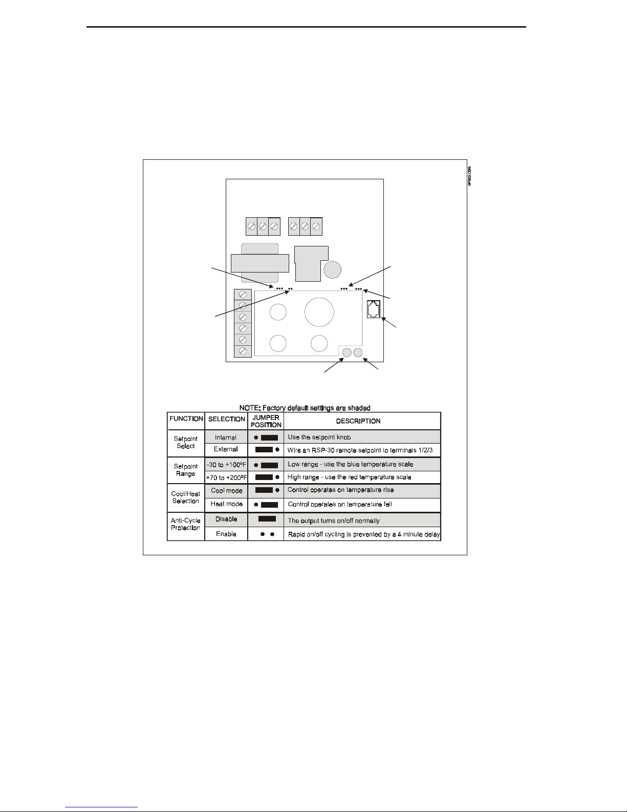
Setup
The SP-30 and SP-30D can be configured to
operate in a variety of applications using jumpers
located on the circuit board (see diagram below).
Set these jumpers based on your application,
before attempting to install or wire the control.
The jumper functions and appropriate positions
are shown in the diagram below.
SETPOINT
DIFF 1
R
C
1
2
3
4
Setpoint
Selection
Anti-Cycle
Protection
Cool/Heat
Selection
Setpoint
Range
Connector
for TD-30
Power LED
Output LED
Page 3
Page 3
Installation Installation
Installation Installation
Installation
(Continued)(Continued)
(Continued)(Continued)
(Continued)
Mounting
The SP-30 and SP-30D controls are designed for
mounting indoors, protected from the weather and
with non-condensing humidity. For outdoor use
or in moist environments use a Goldine RE-1
raintight enclosure. Use the mounting screws
supplied or optional mounting bracket (consult IE
factory).
Sensor Mounting and Wiring
To maximize temperature measurement accuracy
securely mount the sensor and then insulate it to
protect it from the effects of ambient temperature.
18 AWG twisted pair wire should be used for
normal indoor runs. Sensor wiring run outdoors
must be rated for outdoor use and ensure that wire
connections are protected from the weather. For
long runs or runs near other electrical wiring use
shielded cable (Belden 8760 for indoor use or
Belden 8428 for outdoor use). Ground the shields
to one of the control's cover screws. If the SW
sensor supplied with the control does not meet
your needs, contact your distributor for information on the wide range of interchangeable Goldline
temperature sensors.
The temperature sensor wires run back to the
control should be connected to the screw terminals labeled "3" and "4". See diagram on page 5.
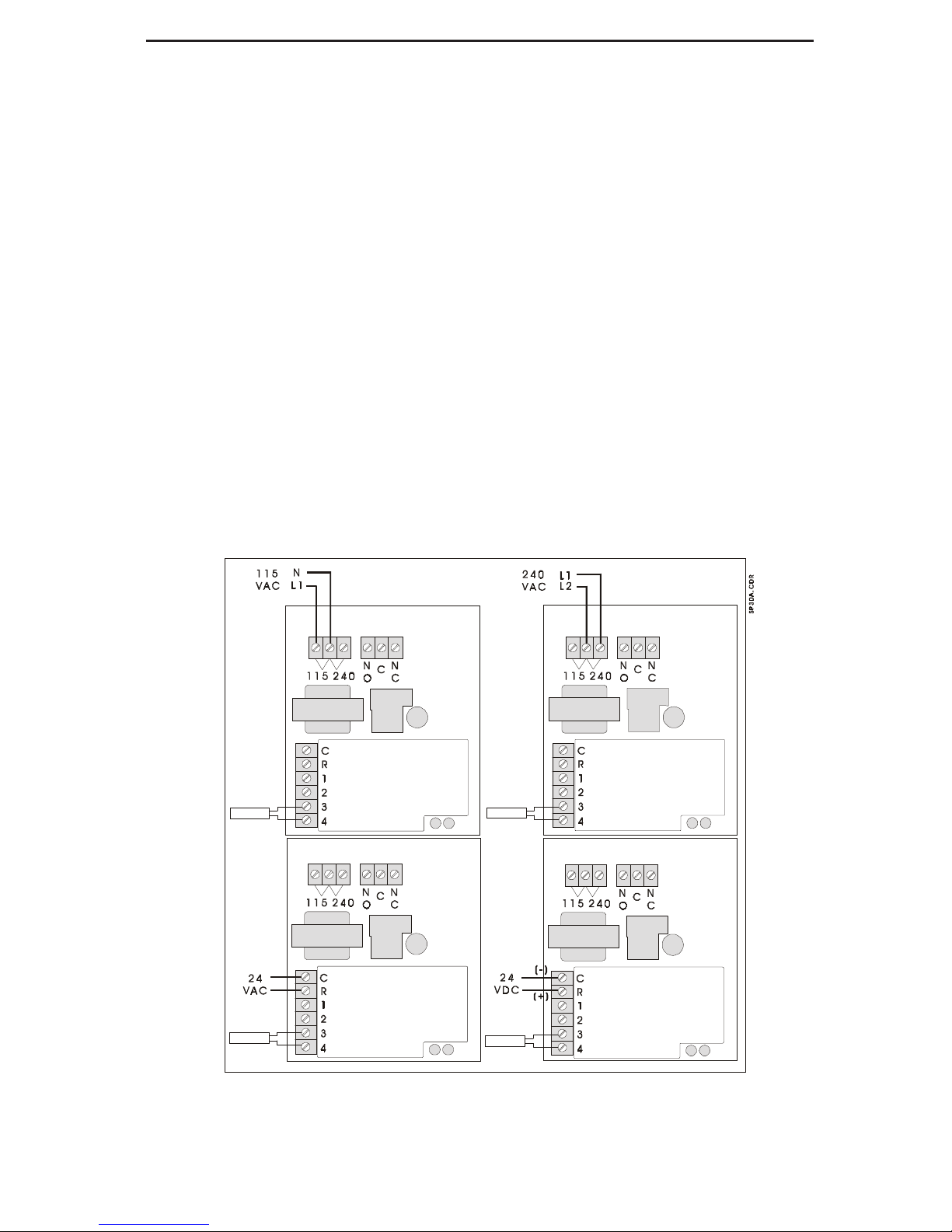
Power input
The SP-30 and SP-30D controls require power to
operate. Either 24VAC, 24VDC, 115 or 208/
240VAC can be used. Be sure to only power the
control with ONE power input. Connect 24VAC
to the “R” and “C” terminals; 24VDC to the “R”
(+) and “C” (-); 115VAC to the terminals marked
“115VAC” or 208/240VAC to the terminals
marked “240VAC”. Connect grounds to the green
screw provided or use grounding clips (eg Steel
City “Gee clips” or Raco #975). Refer to wiring
diagram below.
{
{
Sensor
Sensor
Sensor
Sensor
Page 4

Page 4
Output wiring
SP-30: The SP-30 provides one set of isolated
SPDT relay outputs. If you are directly controlling a load (eg pump, blower, valve, etc), you must
connect a source of power through this output
relay. “NO” are normally open contacts which
close when the control output is on. “NC” are
normally closed contacts which open when the
control output is on. Refer to the sample diagrams
shown below.
SP-30D: The SP-30D provides two sets of isolated SPDT relay outputs. If you are directly
controlling a load (eg pump, blower, valve, etc),
you must connect a source of power through these
output relays. “NO” are normally open contacts
which close when the control output is on. “NC”
are normally closed contacts which open when the
control output is on. Refer to the sample diagrams
shown below.
Installation Installation
Installation Installation
Installation
(Continued)(Continued)
(Continued)(Continued)
(Continued)
{
{
{
{
Sensor
Sensor
Sensor
Sensor
Page 5

Page 5
OperationOperation
OperationOperation
Operation
SP-30E.CDR
LEDs
The SP-30 and SP-30D use 2 LED indicators to
display the status of the control. The diagram on
page 2 shows the location of each LED. Refer to
the chart below for LED information.
Anti-Cycle
This feature is used to prevent the output from
turning on within 4 minutes of output turning off,
regardless of temperature. An internal timer starts
counting immediately after the control "satisfies"
(output relay(s) turn off). The output relay(s) are
only allowed to energize AFTER the timer has
completed counting. If the timer hasn't finished
counting, the Output LED will blink.
NOTE: When input power is first applied to the
control, the Anti-Cycle internal timer automatically starts and will prevent the output relay(s)
from energizing until after the timer has finished
counting.
The SP-30 and SP-30D operation is straightforward.
Cool mode: The control output will turn on when
the sensor temperature rises to the setpoint temperature plus the differential amount. The control
output will turn off when the sensor temperature
reaches the setpoint temperature.
Heat mode: The control output will turn on when
the sensor temperature falls to the setpoint temperature minus the differential amount. The control output will turn off when the sensor temperature reaches the setpoint temperature.
Some sample diagrams of the control logic are
shown below.
Page 6

Page 6
Using the optional RSP-30
The RSP-30 is a remote setpoint adjustment and
can be mounted up to 500 feet away from the SP30 or SP30D control. Be sure to move the Setpoint
Selection jumper to the "External" position and
the Setpoint Range to the desired temperature
range, when using the RSP-30. See included
instructions for mounting information. The RSP30 uses a 3 conductor connection to the SP-30/
30D controls. A 3 position screw terminal block
Operation Operation
Operation Operation
Operation
(Continued)(Continued)
(Continued)(Continued)
(Continued)
on the RSP-30 is labeled "1", "2", and "3", similar
to the screw terminal located under "R" and "C" on
the SP-30/30D controls. Using 3 conductor wire,
connect each pair of similarly marked screw terminals. Refer to the diagram below.
Adjustments
Adjust the setpoint and differential to the desired
settings.
AccessoriesAccessories
AccessoriesAccessories
Accessories
Contact you Goldline Dealer for these accesories:
• TD-30 - digital display
• TDA-30 - digital display with alarm
• RSP-30 - remote setpoint
• full line of sensors
Page 7

°F OHMS °F OHMS °F OHMS °F OHMS °F OHMS °F OHMS °F OHMS
-50 491,142 0 85,387 50 19,900 100 5,827 150 2,044 200 829 250 378
-49 472,642 1 82,719 51 19,377 101 5,697 151 2,005 201 815 251 373
-48 454,909 2 80,142 52 18,870 102 5,570 152 1,966 202 802 252 367
-47 437,907 3 77,656 53 18,377 103 5,446 153 1,929 203 788 253 362
-46 421,602 4 75,255 54 17,899 104 5,326 154 1,892 204 775 254 357
-45 405,965 5 72,937 55 17,435 105 5,208 155 1,856 205 763 255 352
-44 390,966 6 70,698 56 16,985 106 5,094 156 1,821 206 750 256 347
-43 376,577 7 68,535 57 16,548 107 4,982 157 1,787 207 738 257 342
-42 362,770 8 66,447 58 16,123 108 4,873 158 1,753 208 726 258 337
-41 349,522 9 64,428 59 15,711 109 4,767 159 1,720 209 714 259 332
-40 336,804 10 62,479 60 15,310 110 4,664 160 1,688 210 702 260 327
-39 324,597 11 60,595 61 14,921 111 4,563 161 1,657 211 691 261 323
-38 312,876 12 58,774 62 14,543 112 4,464 162 1,626 212 680 262 318
-37 301,622 13 57,014 63 14,176 113 4,368 163 1,596 213 669 263 314
-36 290,813 14 55,313 64 13,820 114 4,274 164 1,567 214 658 264 309
-35 280,433 15 53,669 65 13,473 115 4,183 165 1,538 215 648 265 305
-34 270,460 16 52,078 66 13,136 116 4,094 166 1509 216 637 266 301
-33 260,878 17 50,541 67 12,809 117 4,007 167 1,482 217 627 267 296
-32 251,670 18 49,054 68 12,491 118 3,922 168 1,455 218 617 268 292
-31 242,821 19 47,616 69 12,182 119 3,839 169 1,428 219 607 269 288
-30 234,316 20 46,225 70 11,882 120 3,758 170 1,402 220 598 270 284
-29 226,138 21 44,879 71 11,589 121 3,679 171 1,377 221 588 271 280
-28 218,276 22 43,577 72 11,305 122 3,602 172 1,352 222 579 272 276
-27 210,716 23 42,318 73 11,029 123 3,527 173 1,328 223 570 273 273
-26 203,445 24 41,099 74 10,761 124 3,454 174 1,304 224 561 274 269
-25 196,451 25 39,919 75 10,500 125 3,382 175 1,281 225 553 275 265
-24 189,722 26 38,777 76 10,246 126 3,312 176 1,258 226 544 276 262
-23 183,248 27 37,671 77 9,999 127 3,244 177 1,235 227 536 277 258
-22 177,019 28 36,601 78 9,758 128 3,177 178 1,213 228 527 278 255
-21 171,023 29 35,565 79 9,525 129 3,112 179 1,192 229 519 279 251
-20 165,251 30 34,561 80 9,297 130 3,049 180 1,171 230 511 280 248
-19 159,696 31 33,590 81 9,076 131 2,987 181 1,150 231 503 281 244
-18 154,347 32 32,648 82 8,861 132 2,926 182 1,130 232 496 282 241
-17 149,197 33 31,737 83 8,651 133 2,867 183 1,110 233 488 283 238
-16 144,236 34 30,853 84 8,447 134 2,809 184 1,091 234 481 284 235
-15 139,458 35 29,998 85 8,249 135 2,752 185 1,072 235 473 285 232
-14 134,855 36 29,169 86 8,056 136 2,697 186 1,054 236 466 286 229
-13 130,420 37 28,365 87 7,867 137 2,643 187 1,035 237 459 287 225
-12 126,147 38 27,587 88 7,684 138 2,591 188 1,017 238 452 288 223
-11 122,030 39 26,832 89 7,506 139 2,539 189 1,000 239 445 289 220
-10 118,061 40 26,100 90 7,333 140 2,489 190 983 240 439 290 217
-9 114,235 41 25,391 91 7,164 141 2,440 191 966 241 432 291 214
-8 110,547 42 24,704 92 6,999 142 2,392 192 950 242 426 292 211
-7 106,991 43 24,037 93 6,839 143 2,345 193 933 243 420 293 208
-6 103,561 44 23,391 94 6,683 144 2,299 194 918 244 413 294 206
-5 100,254 45 22,764 95 6,530 145 2,254 195 902 245 407 295 203
-4 97,063 46 22,156 96 6,382 146 2,210 196 887 246 401 296 200
-3 93,986 47 21,566 97 6,238 147 2,167 197 872 247 395 297 198
-2 91,017 48 20,993 98 6,097 148 2,125 198 857 248 390 298 195
-1 88,152 49 20,438 99 5,960 149 2,084 199 843 249 384 299 193
300 190
Temperature vs. Resistance ChartTemperature vs. Resistance Chart
Temperature vs. Resistance ChartTemperature vs. Resistance Chart
Temperature vs. Resistance Chart
All Goldline controls use 10K thermistor sensors. When disconnected from the control, the sensor will
read 10 K ohms at 25°C/77°F. Refer to the chart below for the resistance at other temperatures. For a given
temperature, the resistance is accurate to +/- 1%. For a given resistance the temperature is accurate to +/
- 0.5°F.
GOLDLINE CONTROLS
42 Ladd Street, East Greenwich, RI 02818
(401) 884-6990 (800) 343-0826 (401) 885-1500 fax
134008b
Technical AssistanceTechnical Assistance
Technical AssistanceTechnical Assistance
Technical Assistance
For help in installing, operating, or troubleshooting this control, you may call for technical assistance at 800-343-0826. Goldline Controls techni-
cians are available from 8:00AM to 5:00PM Eastern Time, Monday through Friday. You may call
at other times and leave a message, and a technician will call you back as soon as possible.
 Loading...