

Good Water Warehouse Inc.
1700 E Walnut Ave
Fullerton CA 92831
(714) 441-2893
(714) 441-0525 FAX
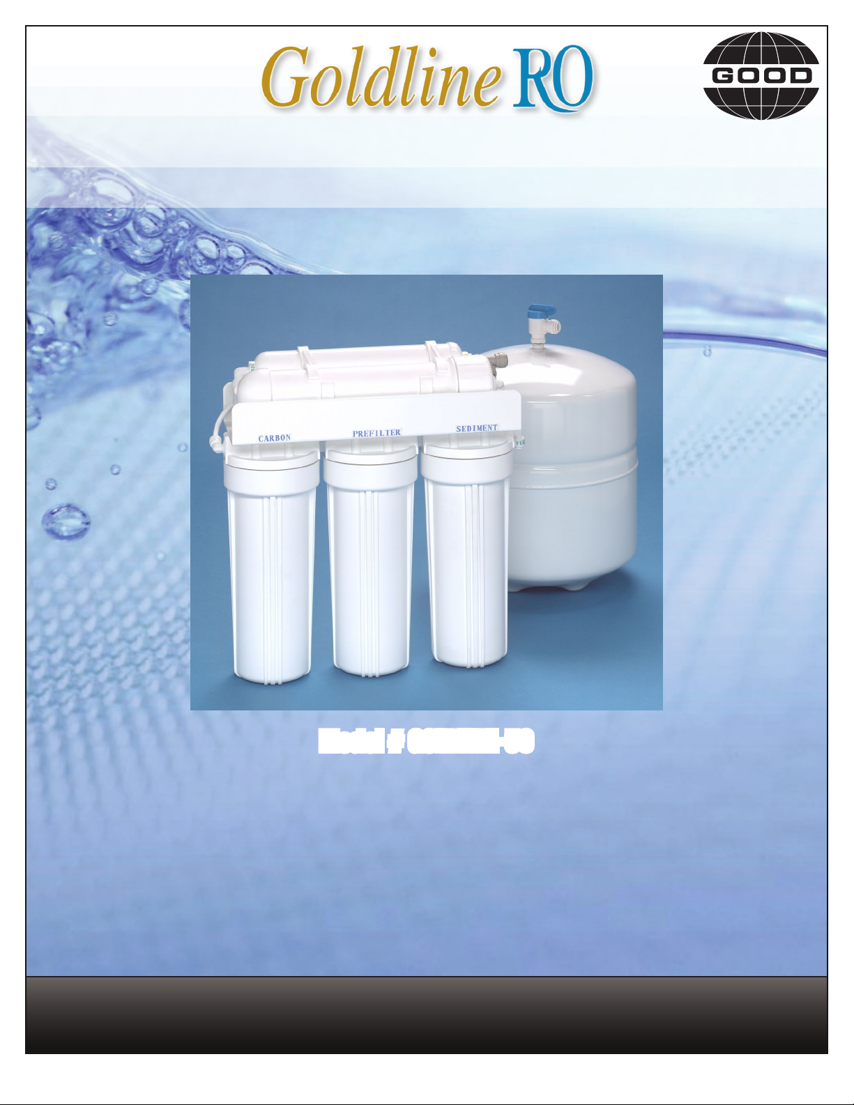
Reverse Osmosis System
Installation & Service Guide
Model # GOLDLINE-50
Please read this manual carefully
before attempting installation.
(1)
GoldLine Manual Introduction
The Goldline reverse osmosis drinking water system is designed for easy installation and maintenance. You will insure a successful installation
as well as reliable operation by carefully reading this manual and following the operational guidelines. Please note that routine maintenance is
essential to the longevity and performance of the system. Filters should be changed every six months (see below) depending on the quality of the
feed water supply. The Goldline RO installation should comply with all state and local laws and regulations. Manufacturer recommends
a TDS test every six months by your authorized dealer. Manufacturer recommends a Nitrate/Nitrite test every six months by your
authorized dealer. This reverse osmosis system contains a replaceable component critical to the efciency of the system. Replacement of the
reverse osmosis component should be with one of identical specications, as dened by the manufacturer, to assure the same efciency and
contaminant reduction performance.
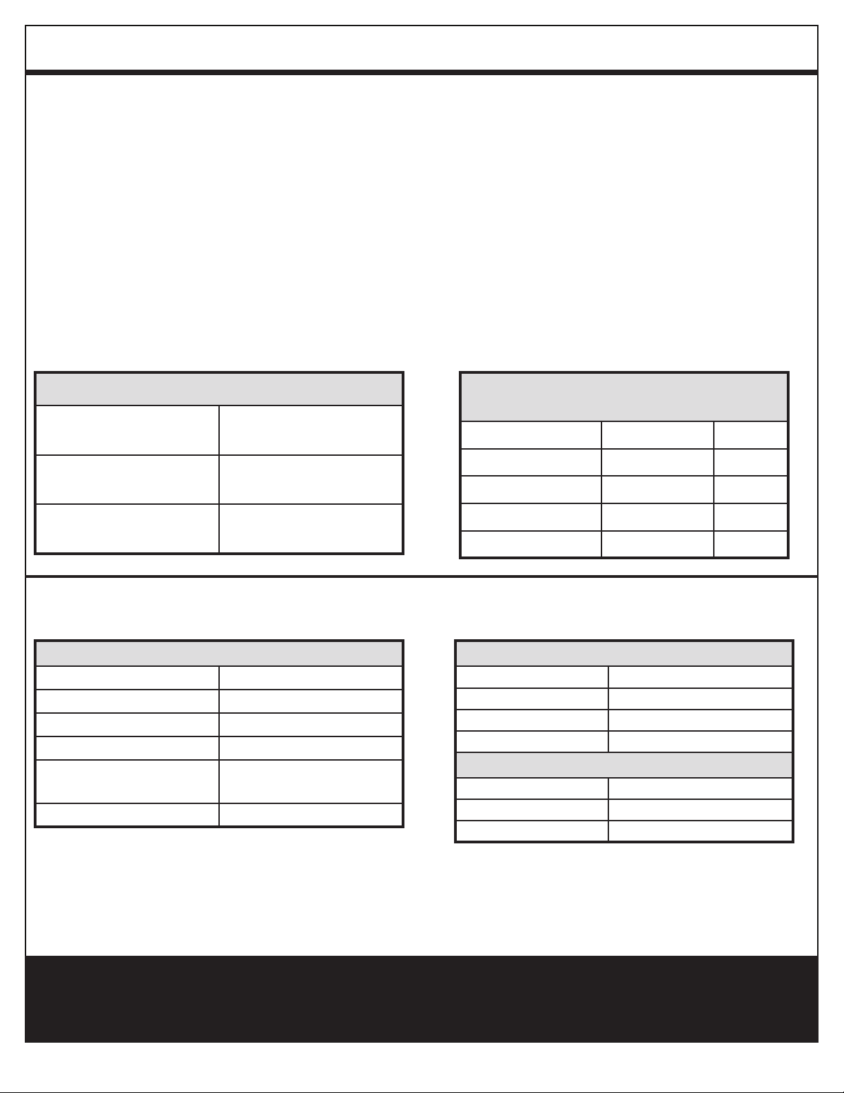
Necessary Installation Tools
Recommended Filter & Membrane
Replacement Schedule
• Variable speed drill • Teon tape
• Relton Drill • Small knife
• 1" hole saw • Phillips screw driver
Filter/Membrane Part # Frequency
Sediment 93023 6 months
Carbon Block Prelter 32-250-125-975 6 months
Carbon Postlter CL10ROT40-B 6 months
* RO Membrane 555694-00 2-5 years
Conditions for Operation of TFC - Thin Film Composite Membrane
Used in the Goldline-50
Source Water Supply - TFC
Community / Private Bacteriologically Safe
System Pressure min/max 30 / 100 psi
Temperature 4º / 38ºC (40º / 100º F)
pH Range 3.0 to 11.0
Maximum supply TDS
level
Turbidity < 1.0 net turbidity (NTU)
1
Efciency rating means the percentage of the inuent water to the
system that is available to the user as reverse osmosis treated water
under operating conditions that approximate typical daily usage
1800 mg/L
Test parameters: 25º± 1ºC, 50 psi and pH of 7.5
2
Recovery rating means the percentage of the inuent water to the
membrane portion of the system that is available to the user as reverse
osmosis treated water when the system is operated without a storage
tank or when the storage tank is bypassed.
Chemical Parameters - TFC
Hardness (CaCo3)
Iron (Fe) < 0.1 mg/L
Manganese (Mn) < 0.05 mg/L
Hydrogen Sulde (H2S) 0.00 mg/L
< 170 mg/L (< 10 gpg)
Production Rate
1
Efciency Rate 8.67%
2
Recovery Rate 23.87 %
Daily Production Rate 10.22 gpd
Caution: Do not use with water that is microbiologically unsafe or of unknown quality without
adequate disinfection before or after the system.
(2)
Starting Your Installation
(4)
Preparation
Check the following list of components to ensure that all
parts are packed with your system.
Compression ttings are used on the supply feed and
drain connector. To insure a optimal seal, tubing should
be cut with the end square. An angled cut or distortion
of the tubing will not provide an efcient seal and may
cause leaks.
Starting Your Installation
Determine the location for the installation of the RO
system. Avoid locations where the system might come in
contact with hot water pipes or other hazards. Determine
the location for the faucet. Check to see that drilling
the faucet hole will not damage pipes or wires running
underneath the sink. Determine the location for the storage
tank. A maximum distance from tank to faucet of 15 feet
is possible. The system will produce a faster ow at the
faucet with the shortest tubing run from tank to faucet.
Check to see that no damage has occurred during shipment,
all connectors are secure, and there are no leaks once the
system is hooked up. Close inspection of the system should
be performed during the rst week of operation.
Shutting Off the Water
Locate the water shut-off valve for the cold water feed line
you choose to use for the supply. Accidentally hooking up
the system to the hot supply line will permanently damage
the membrane (See Conditions for operation). To assure
you are using the cold water line, turn on both the hot and
cold faucet. After the water is warm to the touch, feel the
pipes under the sink. It will be easy to identify the hot and
cold pipes.
Close the cold water valve. Turn on the cold water faucet
only to assure that the line is completely shut off and the
line is drained. If no shut off valve is located under the
sink, turn off the main supply at the entry to the house.
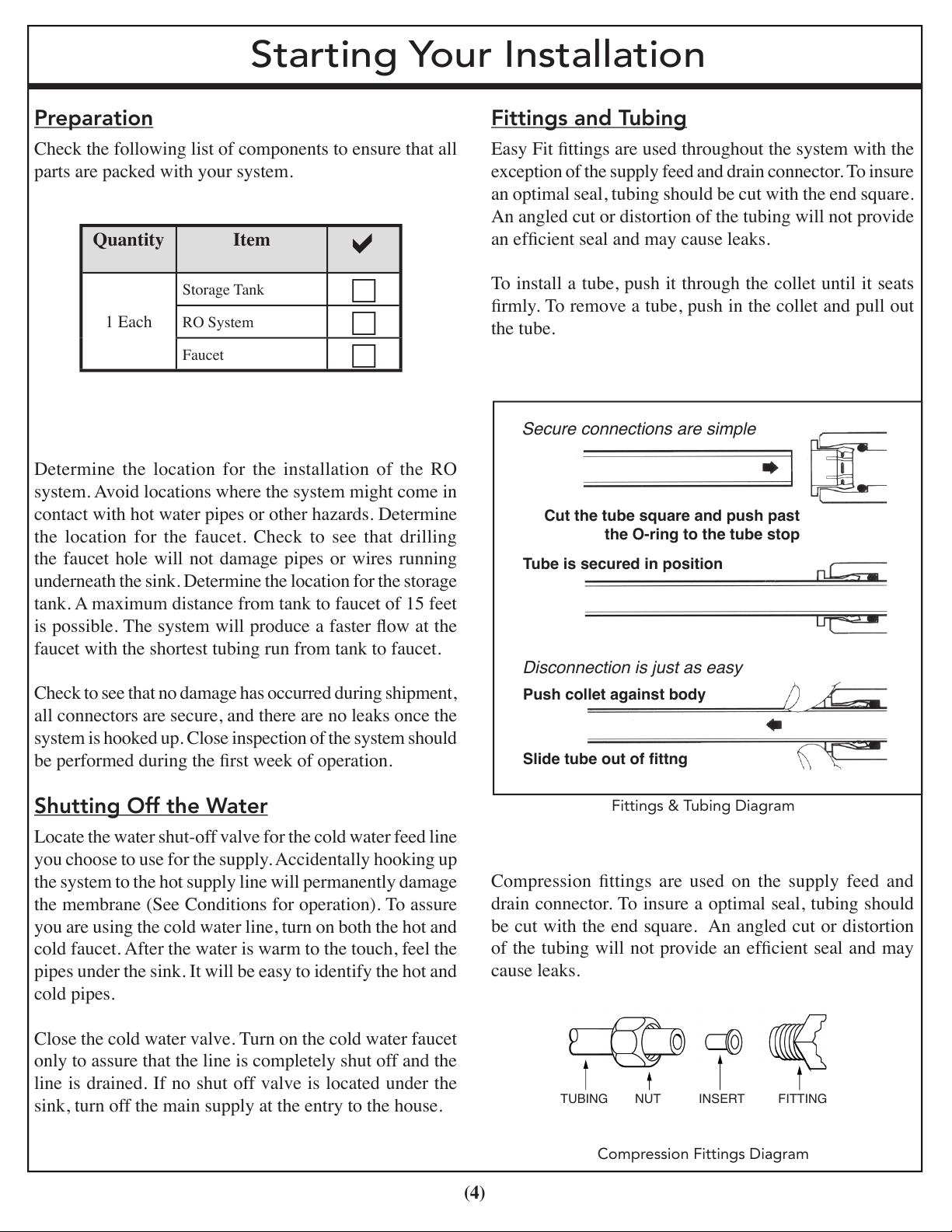
Fittings and Tubing
Easy Fit ttings are used throughout the system with the
exception of the supply feed and drain connector. To insure
an optimal seal, tubing should be cut with the end square.
An angled cut or distortion of the tubing will not provide
an efcient seal and may cause leaks.
To install a tube, push it through the collet until it seats
rmly. To remove a tube, push in the collet and pull out
the tube.
Compression Fittings Diagram
Fittings & Tubing Diagram
Quantity Item
a
1 Each
Storage Tank
c
RO System
c
Faucet
c
TUBING NUT INSERT FITTING
Cut the tube square and push past
the O-ring to the tube stop
Tube is secured in position
Push collet against body
Slide tube out of ttng
Disconnection is just as easy
Secure connections are simple
Preparation
Check the following list of components to ensure that all
parts are packed with your system.
Quantity Item
Storage Tank
1 Each
Determine the location for the installation of the RO
system. Avoid locations where the system might come in
contact with hot water pipes or other hazards. Determine
the location for the faucet. Check to see that drilling
the faucet hole will not damage pipes or wires running
underneath the sink. Determine the location for the storage
tank. A maximum distance from tank to faucet of 15 feet
is possible. The system will produce a faster ow at the
faucet with the shortest tubing run from tank to faucet.
Check to see that no damage has occurred during shipment,
all connectors are secure, and there are no leaks once the
system is hooked up. Close inspection of the system should
be performed during the rst week of operation.
RO System
Faucet
a
c
c
c
Shutting Off the Water
Locate the water shut-off valve for the cold water feed line
you choose to use for the supply. Accidentally hooking up
the system to the hot supply line will permanently damage
the membrane (See Conditions for operation). To assure
you are using the cold water line, turn on both the hot and
cold faucet. After the water is warm to the touch, feel the
pipes under the sink. It will be easy to identify the hot and
cold pipes.
Close the cold water valve. Turn on the cold water faucet
only to assure that the line is completely shut off and the
line is drained. If no shut off valve is located under the
sink, turn off the main supply at the entry to the house.
Fittings and Tubing
Easy Fit ttings are used throughout the system with the
exception of the supply feed and drain connector. To insure
an optimal seal, tubing should be cut with the end square.
An angled cut or distortion of the tubing will not provide
an efcient seal and may cause leaks.
To install a tube, push it through the collet until it seats
rmly. To remove a tube, push in the collet and pull out
the tube.
Fittings & Tubing Diagram
Compression ttings are used on the supply feed and
drain connector. To insure a optimal seal, tubing should
be cut with the end square. An angled cut or distortion
of the tubing will not provide an efcient seal and may
cause leaks.
Compression Fittings Diagram
(3)
 Loading...