

GOLDEN STATE INSTRUMENT CO GS-16CH264, GS-4CH264, GS-8CH264 User Manual
1
l
GS-16CH264
GS-8CH264
GS-4CH264
16, 8, 4 CHANNEL
H.264 DIGITAL VIDEO RECORDER
User Manual
GS-4/8/16CH264 REV 3 VER 1.0
This document contains preliminary information and subject to change without notice.
2
This symbol is intended to
alert the user to the presence
of unprotected “Dangerous
voltage" within the product's
enclosure that may be strong
enough to cause a risk of
electric shock.
T
his symbol is intended to
alert the user to the presence
of important operating and
maintenance (servicing)
instructions in the literature
accompanying the appliance.
WARNING
TO REDUCE THE RISK OF FIRE OR
ELECTRIC SHOCK, DO NOT EXPOSE
THIS APPLIANCE TO RAIN OR
MOISTURE.
NOTE:
This equipment has been tested
and found to comply with the limits for a
class digital device, pursuant to part 15 of
the FCC Rules. These limits are designed
to provide reasonable protection against
harmful interference when the equipment is
operated in a commercial environment.
This equipment generates, uses, and can
radiate radio frequency energy and, if not
installed and used in accordance with the
instruction manual, may cause harmful
interference to radio communications.
Operation of this equipment in a residential
area is likely to cause harmful interference
in which case the user will be required to
correct the interference at his own expense.
Disposal of Old Electrical & Electronic Equipment
(Applicable in the European
Union and other European countries with separate collection systems)
This symbol on the product or on its packaging indicates that this product shall not be treated
as household waste. Instead it shall be handed over to the applicable collection point for the
recycling of electrical and electronic equipment. By ensuring this product is disposed of
correctly, you will help prevent potential negative consequences for the environment and
human health, which could otherwise be caused by inappropriate waste handling of this
product. The recycling of materials will help to conserve natural resources. For more detailed
information about recycling of this product, please contact your local city office, your household
waste disposal service or the shop where you purchased the product.
Notice: Ghosting or fractured images may occur on the screen when there is a suddenly surge
or lightning stroke which cause damage on IC in the DVRs.
3
Table of Contents
CHAPTER 1 MAIN MENU SETUP____________________________________4
1-1 RECORD SETUP ____________________________________________5
1-1.1 Quality & Frame Rate Setup _____________________________6
1-2 EVENT SETUP ______________________________________________6
1-2.1 MOTION SETUP ________________________________________7
1-2.1.1 MOTION AREA SETUP______________________________7
1-2.2 SENSOR SETUP________________________________________ 8
1-3 SCHEDULE SETUP __________________________________________9
1-3.1 Schedule Record Setup _________________________________9
1-3.2 Holiday Setup_________________________________________10
1-4 CAMERA SETUP ___________________________________________10
1-5 ACCOUNT SETUP __________________________________________11
1-5.1 Permission Setup______________________________________11
1-5.2 User Picture Setup ____________________________________12
1-6 NETWORKING SETUP_______________________________________12
1-6.1 NETWORKING SETUP __________________________________13
1-6.1.1 DHCP ___________________________________________13
1-6.1.2 LAN_____________________________________________13
1-6.1.3 ADSL ___________________________________________14
1-6.1.4 3G______________________________________________14
1-6.2 HTTP Setup___________________________________________15
1-6.3 DDNS Setup __________________________________________16
1-6.4 Mail Setup____________________________________________17
1-7 PTZ & RS485 SETUP _______________________________________18
1-8 SYSTEM SETUP____________________________________________19
1-8.1 DISPLAY SETUP_______________________________________19
1-8.2 DATE/TIME SETUP_____________________________________20
1-8.2.1 CHANGE DATE & TIME____________________________21
1-8.2.2 TIME ZONE AND DAYLIGHT SAVING TIME SETUP ____21
1-8.2.3 INTERNET TIME SETUP ___________________________22
1-8.3 BUZZER & RELAY SETUP ______________________________22
1-8.4 SPOT SETUP _________________________________________23
1-9 UTILITY SETUP ____________________________________________24
1-10 DIAGNOSTIC _____________________________________________25
CHAPTER 2 BACKUP & SEARCH___________________________________26
2-1 BACKUP SETUP ___________________________________________26
2-2 SEARCH SETUP ___________________________________________29
2-2.1 EVENT SEARCH_______________________________________29
2-2.1.1 CRITERIA SETUP FOR EVENT SEARCH______________30
2-2.2 TIME SEARCH ________________________________________31
CHAPTER 3 Remote Software Installation and Setup____________________32
3-1 Remote Software Installation and instruction___________________32
3-2 How to do remote monitoring through IE _____________________34
3-3 How to do remote monitoring through JPEG VIEWER(Only Monitor
Function)_____________________________________________________35
3-4 Remote Viewing Software Instructions ________________________37
4
CHAPTER 1 MAIN MENU SETUP
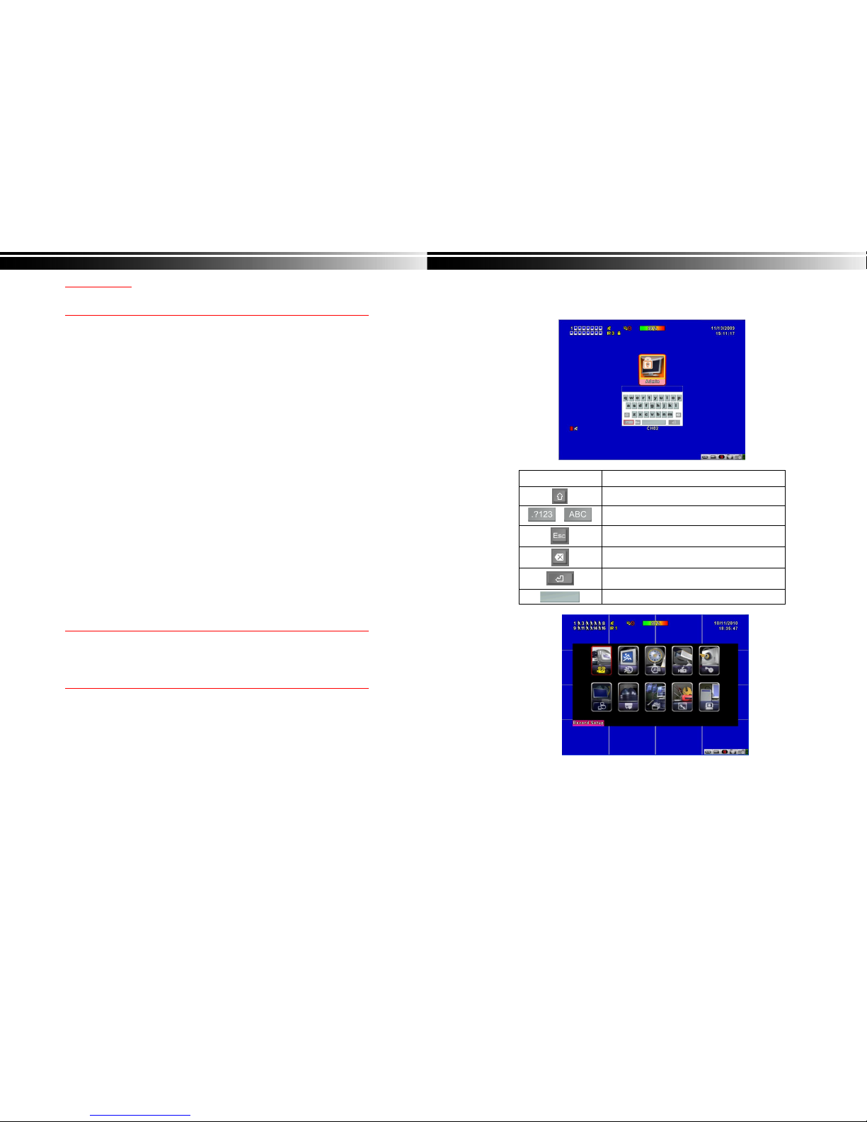
To enter the main menu and set up DVR, log-in account and user password are required.
The default password of the administrator is “123456”. Please check the “Account Setup” for
related setup of other log-in users.
Table 1-0.1 Some definition of virtual keyboard.
Item Description
Switch between capital and small letters.
/
Switch between numbers and letters.
Press to cancel the setup, and re-choose the login
account.
Delete the last character.
Enter to identify the password. It will enter the set
up menu, If the password is verified.
Space key

5
Table 1-0.2 The operation of remote control under the setting menu
Item Description
Switch to different options under one item
Switch to different items
MENU Save setup and back to LIVE mode
ESC Back to Upper level of menu without saving
ENTER Enter the menu, or display virtual keyboard
PS. The initialization of new-installed HD is required before recording, please refer to “ UTILITY
SETUP” for detail.
1-1 RECORD SETUP
Item Description
HDD FULL
Select STOP to stop recording or OVERWRITE to reuse the
HDD when HDD is full
「
Stop
」:
Stop Recording
「
Overwrite
」:
Start to overwrite that begin from the oldest data
of HDD, and continue to record.
OSD position X
Setup OSD X axis
OSD position Y
Set up OSD y axis
OSD position setup
Set up OSD axis
Video Preservation
Setup the video preservation period. Recorded video will be
deleted automatically after expiry of preservation period.
Quality & Frame Rate
Setup
Setup the quality and frame rate for each channel under normal
recording and event recording type.
Note:4CH DVR will display 4 channels and 8CH DVR will display 8 channels.
6
1-1.1 Quality & Frame Rate Setup
Item Description
Normal setup/
event setup
Select recording mode
Resolution
Select recording resolution: NTSC:360x240, 720x240, 720x480
PAL:352X288,704X288,704X576
Record Type
You can setup quality and FPS separately for record type.
No.
Check/uncheck the box enable/disable selected channel recording
Quality
Select quality: Below Basic/ Basic/ Normal/ High/ Highest
FPS
Select recording frame rate.
(The number of sheets in accordance with the actual models)
Auto
Assign each channel with its maximum accessible fps
Note:4CH DVR will display 4 channels and 8CH DVR will display 8 channels.
1-2 EVENT SETUP
Item Description
Motion Setup
Enter to set up motion detection
Sensor Setup
Enter to set up sensor detection
7
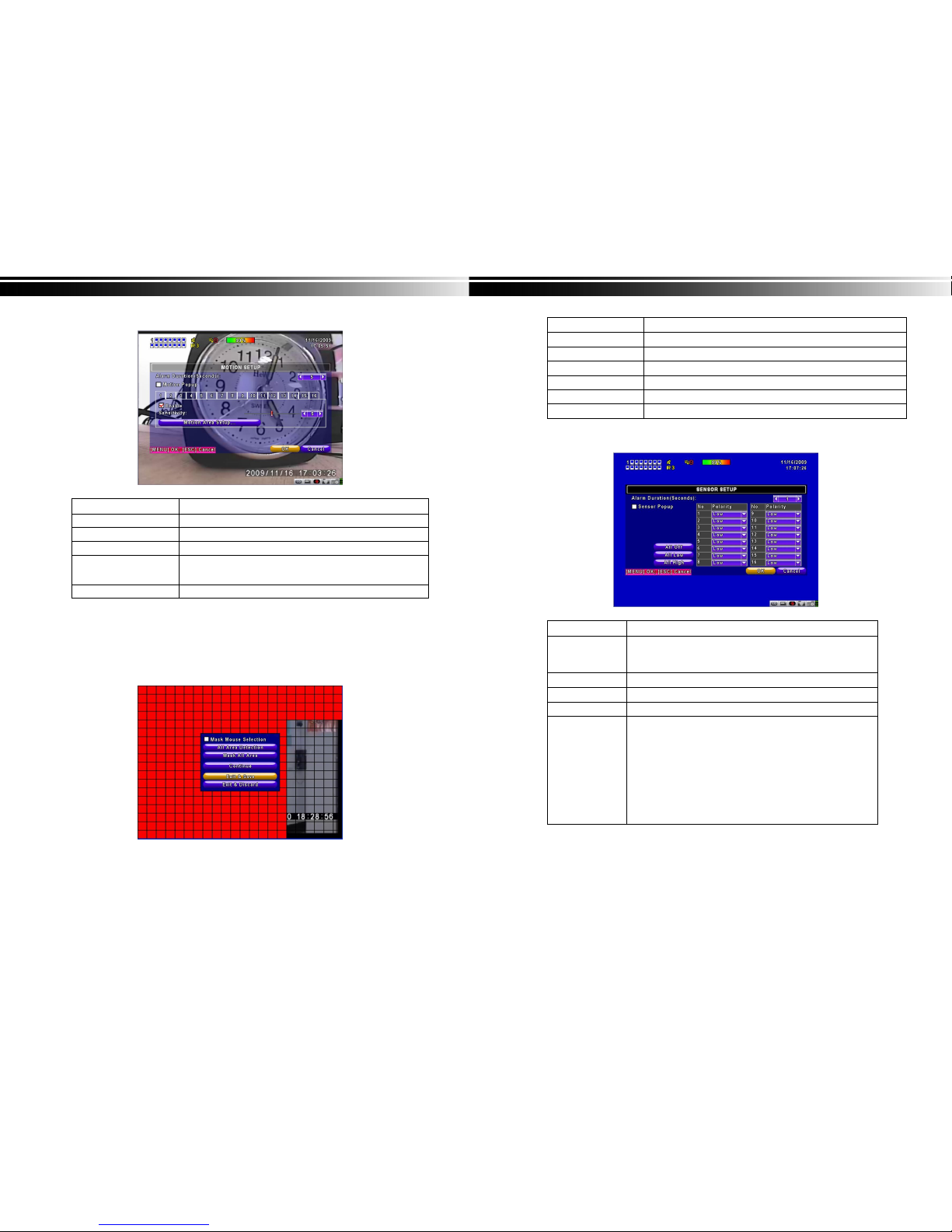
1-2.1 MOTION SETUP
Item Description
Alarm Duration(Seconds)
When motion detect,the number of seconds continuous alarm
1~16
You can setup independently for each channel.
Enable
Check the box to Enable/Disable motion detection for each channel.
Sensitivity
Drag the white bar or press ◀ ▶ to set up Sensitivity from a
Value of 0 to 10 for each channel. The higher value you set t
he more sensitive it will be.
Motion Area Setup
Enter to setup motion detection area
Note:4CH DVR will display 4 channels and 8CH DVR will display 8 channels.
1-2.1.1 MOTION AREA SETUP
The motion detection has been divided into 22x18 grids. The default detection area is
full screen as it marked in transparent for local DVR and purple for remote access.
Areas deselected for motion detection are marked in red for both local and remote site.
8
Item Description
Mask Mouse Selection
Switch between “select” and “deselect” for cursor-dragging function
All Area Detection
Select entire screen as detection area.
Mask All Area
Deselect entire detection area.
Continue
Continue setup
Exit & Save
Save setup and leave
Exit & Discard
Cancel setup and leave
1-2.2 SENSOR SETUP
Item Description
Sensor Popup
Check the box to Enable/Disable popup screen function for all
channels. When Sensor is detected in LIVE mode, the detected
channel image will pop up in full screen display.
All Off
Set all sensor off
All Low
Set all sensor polarity low
All High
Set all sensor polarity high
Sensor Polarity
Click or press ▼ to select between HIGH, LOW voltage for
triggering sensor detection or OFF to turn off polarity for each
channel
Low Polarity:Sensor has not been triggered. When connected,
sensor will be turned on..
High Polarity:Sensor has been triggered. When connected, sensor
status will be turned off..
Off :Sensor is deactivated, and will not be turned on/off.
Note:4CH DVR will display 4 channels and 8CH DVR will display 8 channels.
9
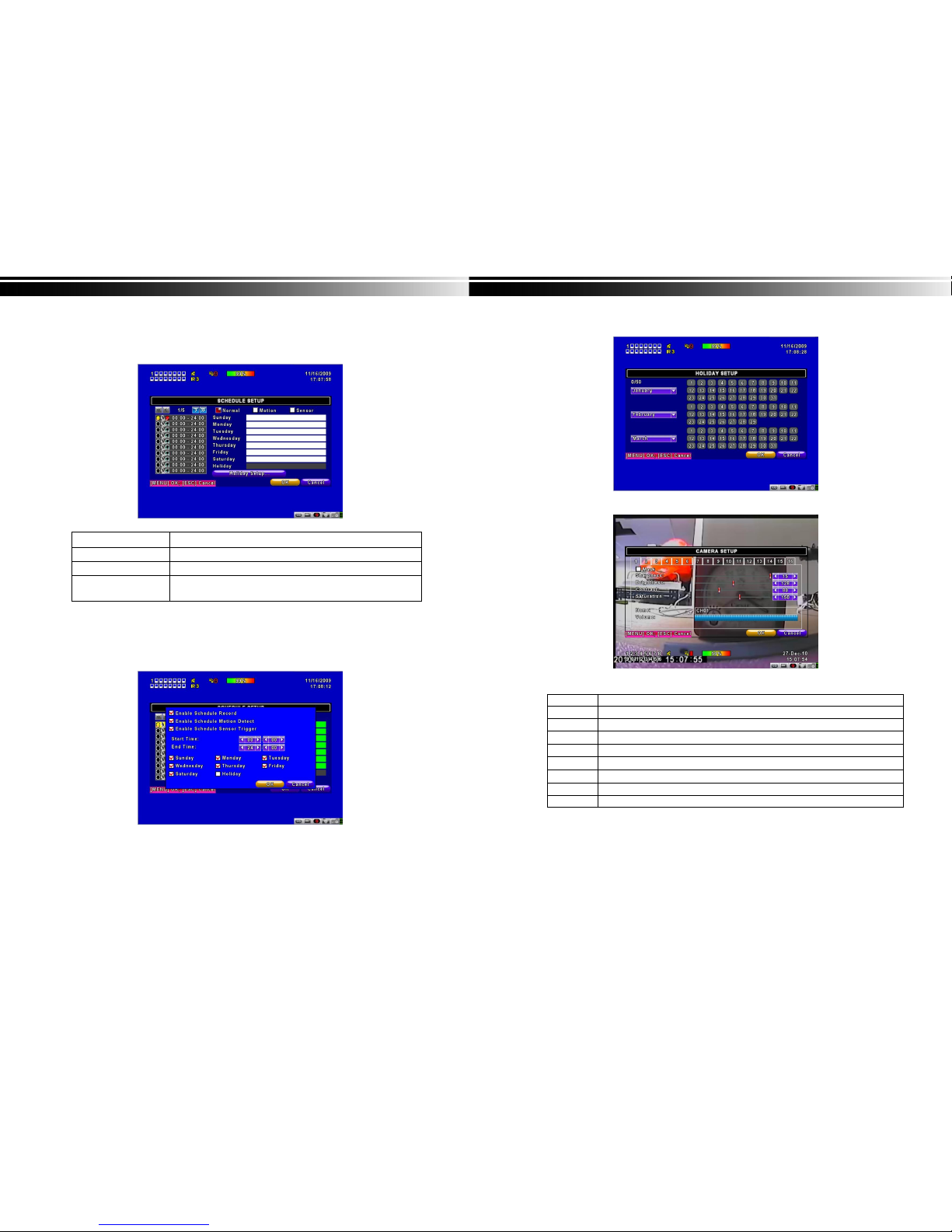
1-3 SCHEDULE SETUP
Except from starting recording manually, you can also setup the recording time by weeks
and schedule including normal, motion detect, and recording type.
Item Description
Page
Each page provides 10 schedules for setup. 5 pages in total.
Holiday Setup
Enter to setup holiday, up to 50 days, other than weekends,.
View Event/ Motion/
Sensor Setup
View Normal/ Motion/Sensor
Note:4CH DVR will display 4 channels and 8CH DVR will display 8 channels.
1-3.1 Schedule Record Setup
Click on the time on the left side. The setup menu will be displayed. You can have
detail setup by dates, Time and event.
10
1-3.2 Holiday Setup
Since holidays are different by different country and region, you can setup the holiday of
your location accordingly.
1-4 CAMERA SETUP
Item Description
1~16
You can setup independently for each channel.
Mask
Check the box to Enable/Disable mask function for LIVE mode
Sharpness
Drag the bar or press ◀ ▶ to adjust Sharpness of your camera from value 0 to 15.
Brightness
Drag the bar or press ◀ ▶ to adjust Brightness of your camera from value 1 to 255.
Contrast
Drag the bar or press ◀ ▶ to adjust Contrast of your camera from value 1 to 255.
Saturation
Drag the bar or press ◀ ▶ to adjust Saturation of your camera from value 1 to 255.
Name
Set up name of each channel
Volume
Audio volume under LIVE mode and recording mode can be adjusted.
Note:4CH DVR will display 4 channels and 8CH DVR will display 8 channels.
11
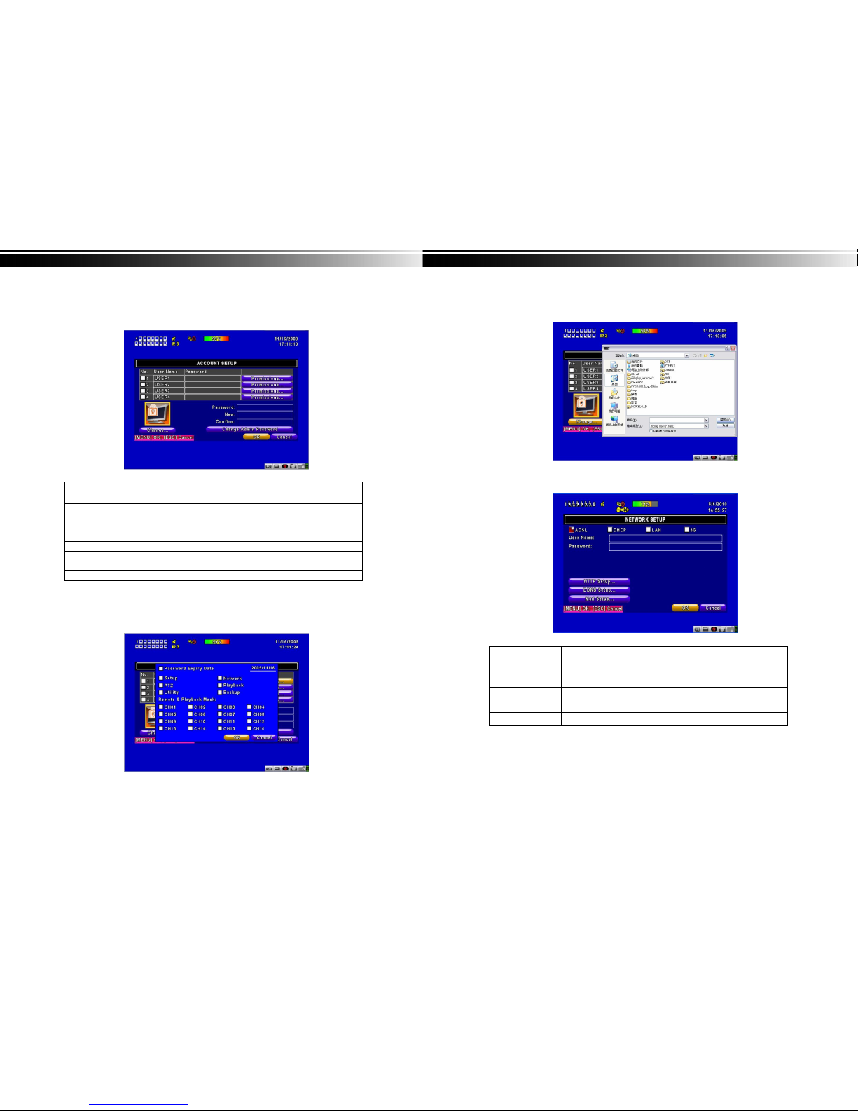
1-5 ACCOUNT SETUP
The Account Setup menu is used to provide role-based permission independently setting for
each user (maximum of 4 users) to access DVR over network. The default admin account and
password is “admin” and “123456”
(The default password remains the same after firmware upgrade)
Item Description
No.
Check to activate the user’s account.
Username
Set up user name
Password
Set up a password for each user. Password is required to have 8
characters and can be a combination of letters and numbers and is
case sensitive.
Permissions
Set up Permissions for each user
Change Admin
Password
Change administrator’s password
Picture
Change the user’s picture
1-5.1 Permission Setup
The Account Setup is set to provide individual user (maximum of 4 users) role-based
permissions, including access to Setup menu, Network operation, PTZ function, Playback,
Utility, Backup, Password expiry date and Mask on specific channels while playing back.
12
1-5.2 User Picture Setup
Users can upload a selected picture from a remote computer
1-6 NETWORKING SETUP
Item Description
Connect type
Setup mode for network connection: (ADSL、DHCP、LAN、3G).
HTTP Setup
Enter to set up HTTP
DDNS Setup
Enter to set up DDNS
Mail Setup
Enter to set up mail
3G Setup
Enter to set up 3G network
 Loading...