

Page 1
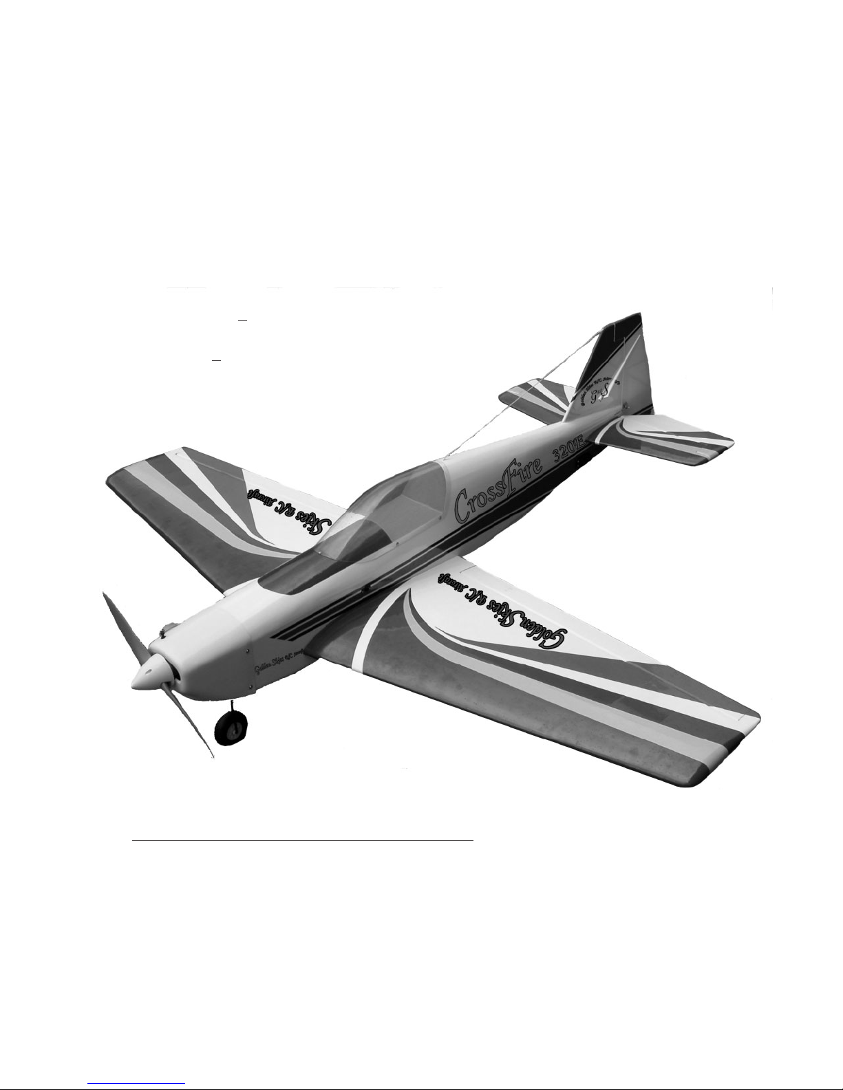
CrossFire 320E
Unlimited Sport-Aerobatics
Professional Quality ARFs for Sport-Pilots
Final Assembly Manual
(refer to http://www.goldenskiesrc.com for complete, updated assembly manual)
Specifications:
Wing Span: 64 + 1/4 in, Area: 779 sq-in;
Wing Loading: 22-23 oz/sqft
Length: 60
Weight: 7 to 8-1/2 pounds (Depends upon equip. used)
Engine: 60 - 90 2/s, 90 - 120 4/s
Radio: 4 ch min, 5 servos
+ 3/8 in;
For Your Ultimate Enjoyment and Safety:
If this is your first ARF or RC model, Golden Skies R/C Aircraft, Inc. (GSRC) recommends that
you seek the knowledge and help of a long time, experienced modeler to assist you in the assembly
of this kit and to assist you in the preflight safety checks and first flights, during which you will be
trimming the plane for safety and performance. Your local hobby shop or the AMA association
(http:www.modelaircraft.org ) can assist you in finding a club, local expertise and a local flying
field. Seek a flying field with an AMA authorized club charter and one that has qualified flying
instructors. This is absolutely mandatory for your safety and the safety of others.
949-429-2910; http://www.goldenskiesrc.com Rev. 1.1 (8-6-04)
60-Size
Almost Ready to Fly
Golden Skies R/C Aircraft, Inc.
30882 Rivera Place, Laguna Niguel, CA 92677
1
Page 2
Optional Equipment and
Accessories
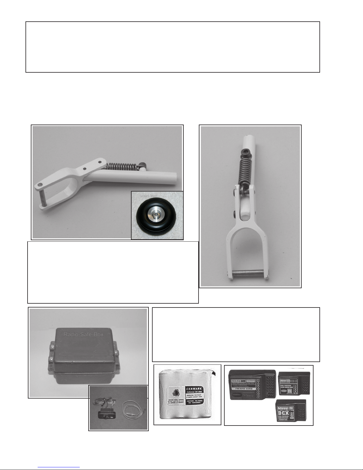
Through out this assembly manual, Golden Skies R/C Aircraft, Inc. (GSRC) will mention
optional installation and assembly procedures along with optional accessories that will enhance the performance, structural integrity, appearance, or safety of your aircraft. Listed and
pictured below are the accessories that are available directly from GSRC:
Spring Loaded, Caster Landing Gear: Add this
gear for the smoothest landings possible. Make a rough
landing and the spring gear smooths it out. Cut off the
torsion wire gear, slip on the spring-gear, tighten two
setscrews and you are ready to go. You still retain the
torsion wire capability and gain spring “shocks”.
Radio Safe-Box:
Add a light weight, Radio-Safe-Box ® to protect
your valuable radio receiver and battery from traumatic
crash damage and make the receiver & battery installation the easiest it has ever been.
Order these optional parts through: http://www.goldenskiesrc.com
Page 3
Optional Equipment - Accessories ............................................................. 2
Table of Contents ...................................................................................... 3
Introduction ............................................................................................. 4
SAFETY WARNING & DISCLAIMER ................................................... 5 - 7
Warranty Statement ................................................................................... 8
Recommendations ..................................................................................... 9 - 10
Tools and Materials Needed ...................................................................... 11
English to Metric Conversion Table .......................................................... 12
Quick Build Process (for experienced builders) ........................................ 12
Assembly Steps: ........................................................................... 13-36
Rapid Assembly Step Order .............................................................................. 12
Step 1: Control Surface Hinge Installation .................................................... 13
Step 2: Wing Servo Construction ................................................................. 14
Step 3: Engine Mount Installation................................................................. 15
Step 4: Wing Panel Joining............................................................................ 16 -17
Step 5: Tail Surfaces, Installation.................................................................. 17 - 18
Step 6: Fuel Tank Assembly.......................................................................... 18 - 19
Step 7: Control Surfaces, Installation (Ailerons, Rudder, Elevator)................ 19 - 20
Step 8: Nose Wheel Assembly....................................................................... 20 - 21
Step 9: Push-rod, Pull-Pull Assembly............................................................ 22 - 24
Step 10: Belly Pan Installation........................................................................ 24 - 25
Step 11: Fuel Tank Installation....................................................................... 25 - 26
Step 12: Engine Installation............................................................................ 26 - 27
Step 13: Cowl Installation.............................................................................. 28 - 29
Step 14: Wheels............................................................................................. 30
Step 15: Radio, Battery, Switch...................................................................... 21 - 32
Spinner .......................................................................................................... 32
Decals ............................................................................................................ 33
Optional Assembly Steps: .................................................................................. 34 - 36
Balancing (Pitch-Roll-Yaw) ............................................................................... 37 - 38
Control Throws ................................................................................................. 38 - 39
Preflight Safety Checking .................................................................................. 39 - 40
Radio Controls .................................................................................................. 41
At the Field ....................................................................................................... 42
Flying ............................................................................................................... 42
Flight Trimming & Performance Chart ............................................................... 43
Supplemental Drawings and Figures ................................................................... 44
Engine Mount (rail separation) & Screw-Bolt Sizes and Drill-Tap Sizes ............. 45
Engine Drawings ............................................................................................... 46
Evaluation Sheet and Mailer .............................................................................. 47
Disclaimer ........................................................................................................ 48-50
3
Page 4

Introduction
We are sincerely pleased that you have purchased the Golden Skies R/C Aircraft (GSRC),
CrossFire 320E ARF and we are sure you will thoroughly enjoy the CrossFire’s ease of assembly
and flight performance. The final assembly manual is written in two sections:
1) For the very experienced builder of ARF type R/C models
2) For the relatively new builder.
For the experienced builder (one who has successfully assembled several ARF kits) we have
a fast build scenario listing the major building steps in a multiplexing order to facilitate a very rapid
build (5-6) hours. For the less experienced builder, we present you with a traditional, step-by-step
building process. For both experienced and less-experienced builders, GSRC recommends you
read the entire manual to get a feel for the building process and the instruction manual. This will
assist you in the building process. If you have any questions about how to build the CrossFire
320E, please either call or email GSRC.
Updated Assembly Manuals are available in Adobe © *.pdf format on our website. Enlarged
and extra assembly pictures are also available, use “CrossFireAM” as a password to access this
website page.
Golden Skies R/C Aircraft, Inc.
Laguna Niguel, CA 92677
949-429-2910
email: [email protected]
http://www.goldenskiesrc.com
(page 12); and,
GSRC, CrossFire 320E Features ......and benefits:
o Computer Aided Design (CAD) ...... ensures accurate, producible parts
o Strong, light weight design and construction ... High power to weight ratio
o Balsa and lite-ply construction ...... repairable with locally available materials
o OraCover ©, Heat Shrinkable Covering .... re-shrink, repairable
o After-Market Quality Hardware ...... The best available, a $35.00 retail value
o Pre-cut and Installed Canopy ...... A clean/accurate installation, time savings
o Pre-cut and drilled Cowl ......... For fast build and easy installation
o Pre-colored Cowl ....... long lasting color, fast build
o Heavy Duty landing gear ...... withstands rough landings
o Pull-Pull Rudder ........ Most positive control, easy adjustments.
o Dual, wing-aileron Servos ..... Low servo loads, quick control, reduced fluttering
o Fully symmetrical Airfoil Tail ..... More positive rudder control, no flat stab seeking
o Fully symmetrical Airfoil Wing ..... Predictable, smooth, stable in any position
o Secondary wing Spars, lite-ply ribs in wing gear area ....... Strength, durability
o Fast build Assembly manual ........ Fast build
o Warranted Firewall Strength ........ Reliability, peace of mind.
(See Optional “Spring-Gear”)
4
Page 5
Safety Warning, Disclaimer and
ASSUMPTION OF RISK
Golden Skies R/C Aircraft, Inc.
Legal Agreements
Warning
The Radio Controlled (R/C), Almost Ready to Fly Aircraft (“ARF”) is NOT A TOY and is
potentially dangerous to property and individuals within several miles of your flying area. It
is capable of causing property damage, serious bodily harm,and possibly death if it strikes
personal property or an individual.
Consumer’s Responsibility
1) Assembly and Use
IT IS YOUR RESPONSIBILITY AND YOURS ALONE to assemble the ARF correctly and to properly install
all additional componentry, both included in the ARF kit and/or acquired by the purchaser of
this ARF; to preflight test the model; and to fly ONLY in an American Model Aeronautics
Association (AMA) approved flying site with the supervision and/or assistance of a fully
qualified flying site instructor. The pilot of this ARF must comply with all of the AMA’s
Safety Codes. The employment of common sense for safety of yourself and others is otherwise
mandatory. The ARF has a radio range of 500 (or less) feet and the pilot is directed not to
exceed this distance when flying the ARF. In the event the range is exceeded, the pilot will
lose control of the ARF which could cause injury and damages to objects which the ARF may come
into contact with upon an uncontrolled landing. Do not attempt to fly this ARF if you have not
been qualified as a solo pilot by the instructor at the AMA approved flying site. It is
recommended that on any first flight of a new R/C aircraft that you attain the assistance or
instruction of a highly experienced R/C pilot to verify the ARF’s construction from a safety
and flight perspective. If you are just starting to fly R/C Model Aircraft of any type, consult
your local Hobby Shop or write to the Academy of model Aeronautics to find an experienced
instructor in your area.
2) Assumption of the Risk
Participation in the operation of remote controlled aircraft is voluntary. I understand that
the operation of remote controlled aircraft is a dangerous sport which can result in bodily
injury, death, and/or damage to property for many reasons, including but not limited to
airplane accidents involving third parties known and unknown to the user; equipment failure,
malfunction, or misuse; weather conditions such as storms and lightning; the training, acts,
omissions, recommendations or advice given by your local Hobby Shop or the Academy of model
Aeronautics concerning the operation of remote controlled aircraft and related activities such
as transportation to and from the site; and first-aid, emergency treatment or other services
rendered to me as a user or others. I understand and acknowledge that the above list of reasons
is not complete or exhaustive. I accept and hereby assume all risks of injury, death, illness
5
Page 6

or disease, or other damage to myself, to others, or to my property which arise from participation
in the referenced activities.
3) Release
I hereby voluntarily release, and forever discharge GOLDEN SKIES R/C AIRCRAFT, INC., a California
Corporation, on its behalf and on the behalf of its successors and assigns, and each of them
(“Golden Skies”) and its subcontractors, and all other persons or entities associated with
it, including other participants, (hereafter collectively the released parties) from all
liability, claims, demands, actions or causes of action for bodily injury, death, illness,
disease or damage to myself, to any participating minor child of mine, or to my property which
are related to, arise out of, or are in any way connected with participation in the above
referenced activities, including but not limited to those arising from any negligent or
reckless acts or omissions or breach of contract of the released parties, or hidden defects in
the equipment used. This release is intended to be as broad and inclusive as is permitted by
California law, and shall be construed and interpreted under California law. If any portion,
clause or sub clause is held invalid, I agree that the balance shall continue in full force and
effect.
4) Maintain Proper Insurance Coverage
It is also mandatory that all R/C airplane pilots obtain adequate insurance through their own
homeowner policy or a separate policy to cover liability in the event of property damage or
injury to individuals or personal property. Additionally, all R/C airplane pilots must join
the AMA to become secondarily insured.
Academy of Model Aeronautics http://www.modelaircraft.org … .
Academy of Model Aeronautics
5151 East Memorial Drive
Muncie, Indiana 47302-9252
800-435-9262
5) Indemnification.
The user of this product agrees to indemnify and defend Golden Skies R/C Aircraft, Inc., a
California Corporation, as well as all employees, shareholders, directors, officers and agents
thereof ( “Golden Skies”) , against any claims, lawsuits or actions arising as a result of the
use of the radio controlled aircraft, and shall pay for all legal expenses incurred by Golden
Skies in connection with the defense of such matters, whether or not such claims are resolved
without trial or other final decision and whether or not such expenses are incurred in the
defense of litigation or simply incurred prior to litigation in connection with an informal
claim. The obligation of the user to indemnify Golden Skies is express and unequivocal. The user
is expressly obligated to indemnify Golden Skies for Golden Skies’ own negligence if any,
which may give rise to any claim arising in connection with the use or misuse of the aircraft
or components thereof
6) No reliance
I acknowledge that I am not relying on any oral, written, or visual representations or
statements made by the released parties, including those made in released parties catalogs or
other promotional material.
6
Page 7

7) Venue
he Venue of any dispute that may arise out of this agreement or otherwise between the parties
T
to which Golden Skies or its agents is a party shall be Superior Court for the State of
California located in the County of Orange.
Return Policy
If you are not prepared to: 1) obtain adequate insurance to operate the ARF; 2)
accept all responsibility for personal property damage and /or bodily injury,
including possible death; and 3) to indemnify the ARF designer, manufacturer,
distributor and retailer for any liability resulting from your actions, return
the complete ARF kit to the point of purchase for a refund. In order to return
the ARF Kit, the following steps must be undertaken: ARF kit must be presented
in its original carton, undamaged and un-assembled. ARF must be in the original
OEM condition and suitable for resale. Purchaser must show valid purchase
receipt. ARF kit must be return to point of purchase with sixty (6) days of
original purchase. A restocking fee may be charged by the retailer. All
shipping and handling cost shall be born by the consumer/purchaser
Governing Law
Any legal action stemming from the purchase or use of this product will be governed by the laws
of the State of California and decided by a court of law in the State of California.
7
Page 8

Warranty Statement:
Warranty
Golden Skies R/C Aircraft (GSR/C) warrants the ARF to be free from defect in both
materials and ARF assembly workmanship for six (6) months from the date of purchase
or the first flight, which ever comes first. GSR/C warranty does not cover the whole or
any component parts thereof damaged by use, misuse, modification, or crash of the
ARF plane. In no case shall Golden Skies R/C Aircraft be liable for the effect(s) of
incidental, consequential or indirect damages as the result of the use or flight of the
ARF product. The warranty is limited to the original ARF purchase amount and shall
not exceed that cost and explicitly excludes the cost of additional ARF and R/C components either installed in or used to construct the ARF that are not included in the original ARF kit. The GRR/C warranty is not transferable under any circumstances.
Governing Law:
Any legal action stemming from the purchase or use of this product will be governed by the laws of
the State of California and decided by a court of law in the State of California in the County of Orange.
Spare and Replacement Parts:
Golden Skies R/C Aircraft stocks a complete line of Spare and/or replacement parts for your
CrossFire 320E ARF. We are trying to keep the replacement costs as low as possible, because we want
you to enjoy your CrossFire with genuine, good looking, factory parts. So, please do not hesitate to
replace broken or worn parts and keep your CrossFire in pristine condition. Consult your local hobby
dealer and ask them to order for you or order directly form Golden Skies R/C Aircraft at the address listed
on the front cover.
CrossFire 320E CrossFIre - II 320E
Ite m Part Number Ite m Part Number
Canopy 10056-00001 Canopy 10056-00031
Cowl 10056-00002 Cowl 10056-00032
Wing (Set) 10056-00003 Wing (S et) 10056-00033
Wing (Left) 10056-00004 Wing (Left) 10056-00034
Wing (Right) 10056-00005 Wing (Right) 10056-00035
Fuselage 10056-00006 Fuselage 10056-00036
Wing Gear (Set) 10056-00007 Wing Gear (Set) 10056-00037
Nose Gear 10056-00008 Nose Gear 10056-00038
Decals 10056-00040 Decals 10056-00040
Spring-Gear 10056-00039 Spring-Gear 10056-00039
Metal Clevis (5) 10056-00041 Metal Clevis(5) 10056-00041
Push-Rods (set) 10056-00042 Push-Rods (set) 10056-00042
Engine Mount 10056-00043 Engine Mount 10056-00043
Wheels (2.25") 10056-00044 Wheels (2.25") 10056-00044
Fuel Tank 10056-00045 Fuel Tank 10056-00045
Battery Switch 10056-00046 Battery Switch 10056-00046
8
Page 9

GSRC GENERAL RECOMMENDATIONS
- Work Area: Keep the work area clean and free of debris and unused tools. This will help
prevent damage to your model. If you set the kit components on tools or debris you can damage the parts.
Cover the work area with a soft cloth (bath towels work well) to prevent unwanted marring or damage to your
model.
- Step-by-step Assembly: If you choose to follow the step-by-step assembly process, check
off the boxes as you complete each assembly step. This will help you remember what is completed and
what remains to be done. Read each assembly step thoroughly and completely to be sure you understand
the assembly process prior to doing the actual assembly.
- Organization: Open the hardware bags as they are needed for assembly per the assembly
manual instructions. Once the hardware bags have been opened, place the parts in a small box or bowl to
prevent loss. You may need several small boxes to keep parts separate.
- Dry-Fittings: Always “dry-fit” all parts in each assembly step to check fit, alignment, and ease
of assembly. This will prevent any surprises when racing against a glue setting-time.
- Take Your Time: In the anticipation of flying your new GSRC model, do not be tempted to
rush the assembly process and put your plane or others at risk.
- Choice of Engines: The CrossFire 320E was designed to fly with a strong “60-Size”, 2-Stroke
engine such as an OS-61FX ®. It will do all “sport-aerobatics” with great authority using the 60-size engine.
You may elect to install a 90-size, 2-stroke; however, it is more power than necessary to fly the CrossFire.
However, if you want to “stick-n-rudder” (SnR) the airplane, the 90-size will add to the “3-D” and “freestyle”
capability typical of SnR flying styles.
You may also choose to use a 90-size 4-stroke engine, such as an OS-91FS ® or equivalent. The 904/s is roughly equivalent to the 60-2/s but has more torque and can accommodate a larger prop. A 120-4/
s is, again, more power than necessary, but a lot of SnR fun. Take care to balance your props and perform
other routine vibration dampening procedures. Vibration in the fuselage, wing and other structural parts will,
in time, weaken your airplane to the point of failure.
- Balance your Props: Always, balance your props. Follow the engine manufacturers recom-
mendations for prop size, and balance the prop. Vibration is your models enemy and will eventually cause
structural failure. The worse and more prolonged the vibration, the sooner the failure will occur. This is true
of all aircraft, whether they be full-size or models.
- Servos: GSRC recommends high quality, ball-bearing servos with either metal gears or high
reliability, resin-composite gears. Metal gears will add weight to the plane, so the resin composites are a
good alternative. Use this type of servo on all control surfaces; however, a “standard” servo is suitable for
the throttle control. GSRC recommends 80-100 in-oz. torque for elevator and rudder whereas you can use
60-80 in-oz (minimum) servos for each wing-aileron servo. As a minimum, the Hitec © HS-545BB is a good
servo and can be used for all control surfaces, and the HS-325HB is suitable for the throttle. Hitec servos
may be ordered through the GSRC website ...... http://www.goldenskiesrc.com.
9
Page 10
Recommendations Continued
- Batteries: 4.8 V, 600 mAh batteries are typical in sport model aircraft, however, GSRC prefers
to use 6.0 V, 1100 mAh batteries for higher torque and greater servo actuation speed. The 6.0 V battery is
heavier by one “cell” (5- vs 4-cells), but GSRC believes in highly aerobatic aircraft such as the CrossFire,
you will be more satisfied with the 6.0 V performance. Also the higher voltage “tends” to provide for better
noise immunity in the receiver, and the 1100 mAh tend to provide for more flying time than a 600 mAh.
- OraCover © Heat-Shrink Covering: OraCover is absolutely the best heat-shrink
covering available of its type. It is durable, repairable, replaceable and re-shrinkable as needed.
normal for the covering to show wrinkling from time to time. As temperature and humidity changes, the
balsa will expand and contract. This is natural and the covering may wrinkle. Simply re-shrink the covering
using a covering heat gun. Heat guns are available from your local hobby dealer.
- Radios (Tx & Rx): All of the name brand radios are good, and GSRC prefers you use the radio
you are most accustomed to and comfortable with. The CrossFire will require four Channels minimum and
possibly a 5-channels if you split your ailerons for flaperon capability. It is a good practice to keep the
Transmitter and Receiver to the same brand; however, servos of a different brand are a generally accepted
practice and should cause no problems. Always check your radio manufacturer’s recommendations. Be
aware that different radio receivers may require a specific servo plug-type to be both mechanically and
electrically compatible.
It is
- Conventions: When the manual refers to left and right, it is in reference to your left or right as
viewed from the fuselage tail looking forward or as if you were sitting in the cockpit. Generally, when
“Increasing a Function” of any entity (such as battery switch, a servo, etc.), the following conventions should
be observed:
- Forward
- Clockwise
- To the right
- Up
Doing the opposite of the above, is considered “Decreasing the Function”
- What you need to complete the CrossFire 320E
- Two 18” Servo Extensions,
- One “Y-harness” servo cable
- One 24” Servo Extension
- One Engine, glow-plug, muffler and suitable propeller
- Five Servos
- Fuel Tubing, 16-20 inches
- “Fuel Stopper” or fuel fulling valves (optional)
- Foam Rudder to pad fuel tank, as desired
- Receiver
- Battery
- Battery Switch
10
Page 11

Tools and Supplies Needed:
The following items will be needed to complete the final assembly of the CrossFire 320E
ARF. The assembler should acquire all needed supplies prior to starting assembly and become
familiar with each item by thoroughly reading the manufacturer’s directions.
Materials:
- C/A medium viscosity adhesive, any brand
- C/A thin viscosity adhesive, any brand
- Epoxy, both 5-minute and 30-minute (2000 pound shear), 2-part epoxy
- C/A Debonder, 1-0z
- Acetone, pint or quart
- Denatured alcohol, pint or quart
- Mixing cups, 1-0z
- Silicon Caulking, white (optional)
- Fiberglass (2-0z) and polyester resin (Optional)
- Clear, polyurethane spray, fuel proof
Tools:
- # 0, # 1 and # 2 Phillips head screw drivers
- # 1 & # 2 Flat blade screw driver
- Adjustable Wrench
- Needle Nose Pliers
- Modeling knife, # 11 blade
- Single edge razor blades
- Electric drill, 1/16” to 1/4” bits in 1/32” increments
- Modeling T-pins
- Sandpaper, 180 to 220 grit
- Dremel © “Moto-Tool” ®, wheel cutter, drum-sander, coarse and fine
- Paper towels and/or soft rags
- Pencil and/or felt tip pens (Sharpie ®)
- Ruler, scale
- Toothpicks
- Center Punch
- Hex driver set, Metric and English
- Nut driver set,
- Clamps, variety (see assembly pictures)
- Epoxy brushes, (Solder flux brush)
- T-square or triangle square
- Incidence Meter, Robart ® Model # 404 Incidence Meter
- Rubber bands, # 64 or stronger
- Covering/sealing iron and/or covering heat gun
11
Page 12
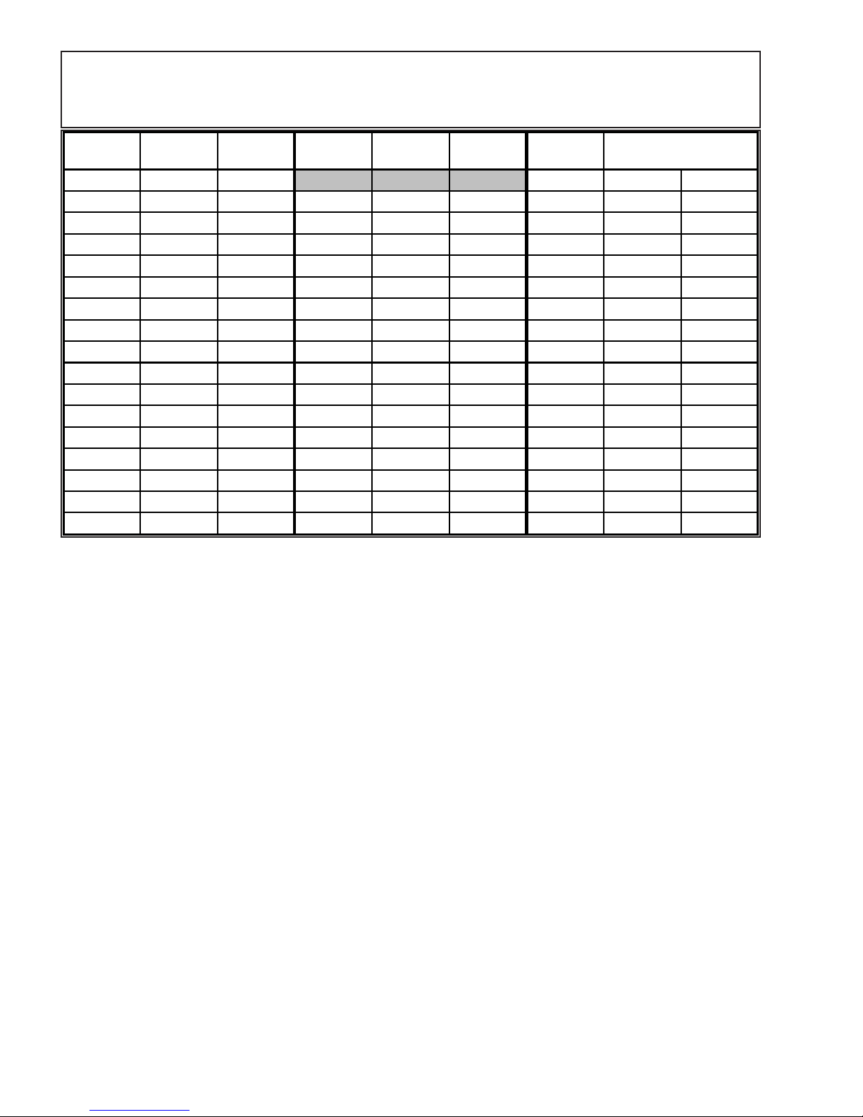
Table 1: English to Metric Conversion Chart
English
(in)
1/64 0.4 0.04 1 25.4 2.54
1/32 0.8 0.08 17/32 13.5 1.35 1.5 38.1 3.81
1/16 1.6 0.16 9/16 14.3 1.43 2 50.8 5.08
3/32 2.4 0.24 19/32 15.1 1.51 2.5 63.5 6.35
1/8 3.2 0.32 5/8 15.9 1.59 3 76.2 7.62
5/32 4.0 0.40 21/32 16.7 1.67 3.5 88.9 8.89
3/16 4.8 0.48 11/16 17.5 1.75 6 152.4 15.24
7/32 5.6 0.56 23/32 18.3 1.83 9 228.6 22.86
1/4 6.4 0.64 3/4 19.1 1.91 12 304.8 30.48
9/32 7.1 0.71 25/32 19.8 1.98 18 457.2 45.72
5/16 7.9 0.79 13/16 20.6 2.06 21 533.4 53.34
11/32 8.7 0.87 27/32 21.4 2.14 24 609.6 60.96
3/8 9.5 0.95 7/8 22.2 2.22 30 762.0 76.20
13/32 10.3 1.03 29/32 23.0 2.30 36 914.4 91.44
7/16 11.1 1.11 15/16 23.8 2.38 40 1016.0 101.60
15/32 11.9 1.19 31/32 24.6 2.46 48 1219.2 121.92
1/2 12.7 1.27 1.00 25.4 2.54 62 1574.8 157.48
Metric
(mm)
Metric
(cm)
English
(in)
Metric
(mm)
Metric
(cm)
English
(in)
Metric
(mm)
Metric
(cm)
Quick Build Step Sequence:
For very experienced builder, follow the building sequence below and refer to the
appropriate pictures or narrative as needed for assistance.
1. Epoxy hinges into all control surfaces
2. Construct the aileron wing servos
3. Install the engine mount
4. Join the wing panels together
5. Install tail surfaces
6. Assembly the fuel tank
7. Attach control surfaces
8. Install nose wheel
9. Install all servos, push-rods, pull-pull rudder system
10. Attach belly pan
11. Install fuel tank
12. Install engine.
13. Install cowl
14. Attach wheels
15. Install Radio Gear
16. Attach Spinner
17. Attach Decals
18. Perform preflight checks
Following this sequence, one should be able assemble the CrossFire 320E in 4-6 hours.
12
Page 13
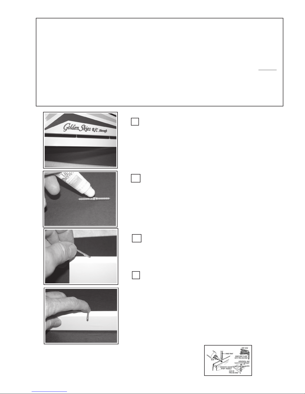
Step 1: Hinge Installation for all Control Surfaces:
In this step, you will install all the hinges into the Ailerons (2), Elevator (2-halves), and
the Rudder. There should be seventeen (17) hinges in all. Three (3) for each elevator
half, three (3) for the Rudder, four (4) for each aileron. You will need a light grease, the 17
hinges, and each control surface. Epoxy the hinges only into the control surfaces, do not
attach control surfaces to its corresponding mating part (i.e. elevator to horizontal stabilizer) at this time.
While the epoxy is curing, move on to Step 2.
Dry Fit Control Surfaces:
Place the hinges into the control surface hinge-holes and slip the
assembly into the corresponding, mating part (i.e. Aileron to wing, elevator to Horz. Stab, etc.) Check for fit and alignment. There should
be no appreciable gap at the hinge line. The hinges’ metal pins should
be at the control surface’s hinge line or pivot point. When satisfied,
continue. Mark the ailerons to know which wing panel they go on.
Grease Hinge Area:
Using a light grease such as Vaseline, lightly cover the entire hinge
area to prevent the epoxy from entering the hinge joint. Take care not
to get grease on the ribbed hinge shank area where it will be glued
into the control surface.
CAUTION: Do not use Oil !
Apply Epoxy to Hinge Hole:
Mix an ample amount of 2-part, 30-minute epoxy following
the epoxy manufacturer’s directions. Apply a sufficient amount, using
a toothpick to the hinge hole and allow to settle into the hole. Wipe off
any excess epoxy from the surface.
Insert the Hinge:
Insert the Hinges into the control surface’s hinge hole. Press the
hinge sufficiently into the hole so that the metal hinge pin is in-line
with the control surface’s hinge point or line. Bend the hinge as shown
in the picture (left) so that the free hinge arm is perpendicular to the
control surface’s hinge line. This will assure that the hinge axis is inline with the control surface’s hinge line.
Repeat this process for all hinge locations on all
control surface. (2-Elevators, Rudder, 2-Ailerons)
13
Courtesy of Robart, Inc
Page 14
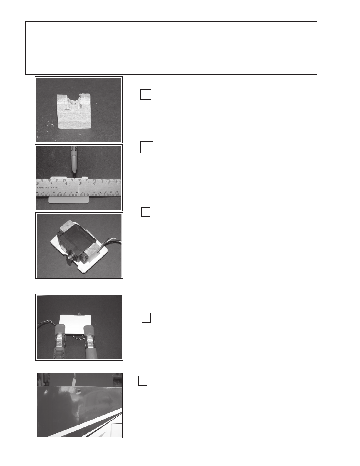
Step 2: Wing Servos & Servo-Wire Extensions:
In this step you will be installing the wing-servos onto the wing-servo access covers and placing the
wing and elevator servo-extension cables in the wings and fuselage respectively.
Hardwood Mounting Blocks: Locate the four hard-
wood servo-mounting blocks. On two of the blocks, cut a
notch ~ 1/4” x 1/4” to accommodate the servo wire. A 1/4” rattail file
works well for this job. Round the edges of the cut to prevent abrading or cutting the servo wire. Make sure the cut is oriented such that
the servo screws will go in the block’s cross-grain.
Prepare the wing-servo Access Covers: On both
wing servo covers, measure the width of the opening-notch
and mark the center of the opening. You will be aligning the servo
arm with this mark. Marking both sides will make it easier to align the
servo. The servo-cover only goes on one way. Please observe that
the notches face toward the wing tips; therefore, the servo-arms in
each wing panel face in opposite directions; i.e.; toward the wing tip.
Mount Servo to Hardwood Blocks: Place the wood
servo blocks against the servo mounting tabs as shown left. Place 2
- 3 pieces of 20 pound paper beneath the servo to raise it off the
surface slightly. While holding the blocks against the servo mark the
mounting holes with a pencil or a punch. Predrill the blocks with a 1/
16” drill bit and mount the servo to the blocks using the servo
manufacturer’s supplied screws.
Now is a good time to mechanically center the servo arms.
Connect the servo to the receiver’s aileron port and turn on your receiver and transmitter. With the aileron controls (stick, trim, subtrims, centering) set to neutral, mechanically mount the servo arm on
the servo shaft, such that it is perpendicular or square with the cover
surface. Repeat this process for both wing servos.
Epoxy Servo Blocks to Cover Plate:
Remove the paper spacer from under the servo and place a
piece of wax paper between the servo, the blocks and the cover plate
to prevent epoxy from getting on the servo. Realign the servo and
mark its position. Mix the two-part, 30-minute epoxy and apply to the
block, reposition the servo on the cover and clamp. Set aside and
repeat process on the other wing servo. Remove wax-paper when
cured.
Install Servo Extension Cables:
Locate the servo extension cable-hole on the top of the wing
near the root rib. Cut an “X” in the covering over the hole. Hold the
wing vertically, with the tip down and feed the 18” extension wire through
the wing and into the servo box. Dress the cable through the hole and
tape-off both ends so that you do not lose the wire. Be sure to note the
“sex” of the connectors so it will mate with the servo connector. (The
Female cable-end goes into the servo box.)
14
Page 15
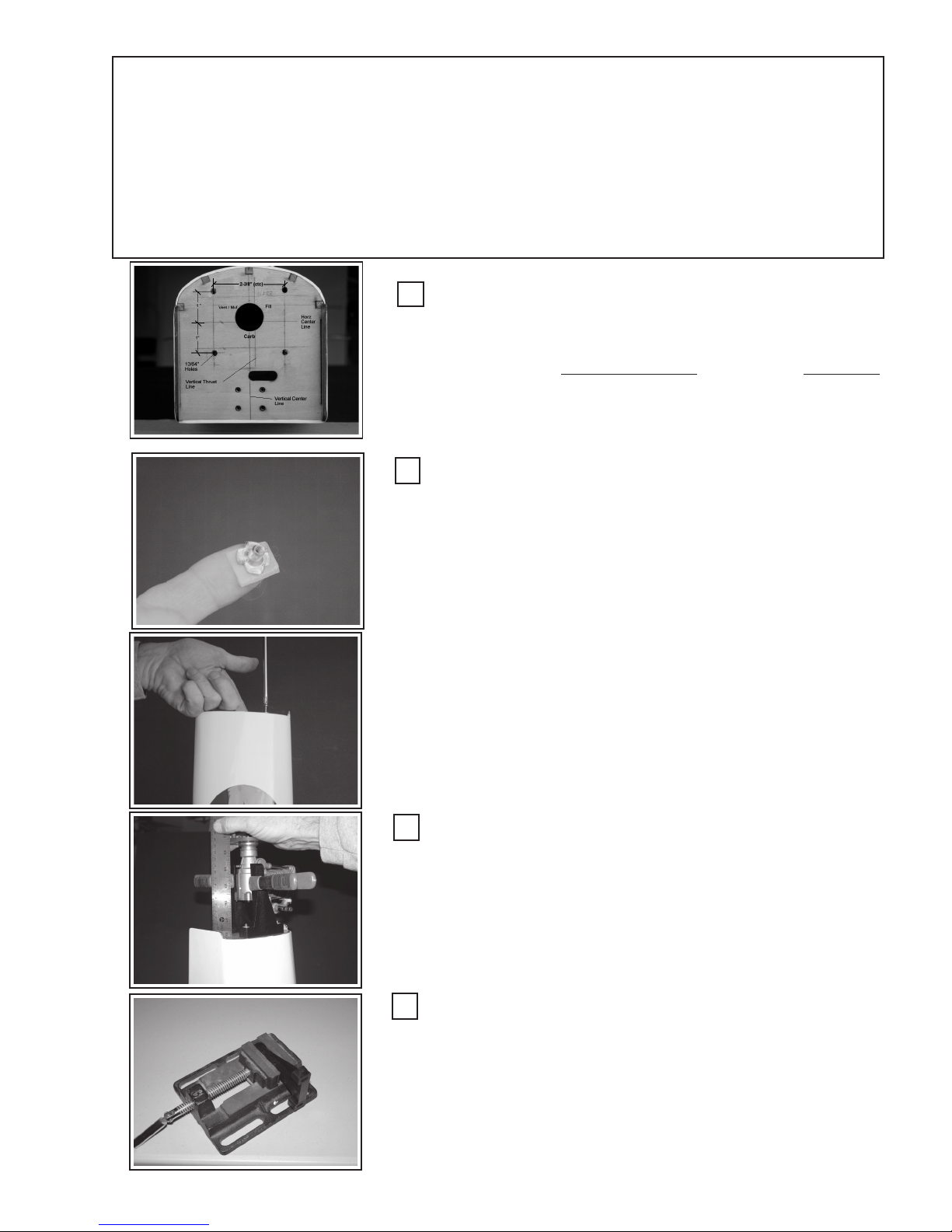
Step 3: Assemble the Engine Mount:
Although GSRC had intended to have the engine mount blind-nuts pre-mounted, but in order
to provide the assembler with the most engine mounting flexibility we allow the assembler to
decide the engine mount orientation. We will show how to side-mount an engine. We will be
showing an OS-91FS®; however, the procedure will be similar for other engines. Take note and
pre-plan for the mounting and thoroughly consider the implications of the muffler and needle
valve locations.
There is ~ 2° right thrust offset built into the fuselage, make reference there.
Locate the Engine Mounting Holes:
Locate the Vertical and Horizontal center lines. If they are not visible, measure and draw them in. The horizontal center line is 3-13/32”
up from the fuselage bottom. Draw two (2) parallel lines, 1-3/16”, one to
the right and left of the vertical thrust line which is 3/32” left* of Vc/l.
Add 0.05” (~3/64”) to the engine-rail separation required by your engine,
(See Table 2), divide this number by two and draw two parallel lines, above
and below, Hc/l. Where the four lines cross, center punch and drill 13/
64” diameter holes for the blind nuts. (*Right if facing the Firewall)
Install Engine Mount Blind-nuts:
Place a washer on one of the engine-mount bolts and have it and a
# 2 phillips screwdriver at hand. Using a piece of tape, make a loop and
stick it to the end of your index finger. Place a blind-nut on the tape as
shown, left. Orient the blind-nut through the fuel tank hole and under
one of the firewall bolt holes. Using the engine-bolt & washer, thread
the bolt into the blind-nut. Tighten with the phillips-head screwdriver to
draw the blind-nut into the back side of the firewall. Repeat this process
for the remaining three engine-mount holes.
Note that the firewall has been marked with the fuel-tank tubing
information. Refer to the fuel tank assembly step for fuel-tank tubing
(port) orientation. The markings refer to: 1) Muffler or Vent port, 2)
Carburetor port, 3) Fill port (the 3rd filling port is optional)
Temporarily attach the engine mounts using the four engine mounting bolts and washers. Snug it down tight; however, it will be removed
later to drill the engine mounting holes in the engine mount rails.
Locate Engine Position:
With the spinner’s backplate on the engine shaft, clamp the
engine to the mount-rails, as shown. Position the engine so that the
rear edge of the spinner backplate is 5-1/2” from the firewall front
surface. Be sure to measure all the way around the backplate to be
sure the backplate is parallel with the firewall and everything is centered and “squared-up). With the engine securely fastened, mark the
engine mounting hole on the mount-rails, using a pencil or center
punch.
Drill Engine Mounting Holes:
Center punch the engine mounting hole locations that you marked
above and place in a drill-press vise or bench vise. Drill the engine
mounting holes for the size of bolt recommended by the engine manu facturer. Attach the engine mount to the firewall. Do not mount the
engine at this time (For 60 - 120 size engines, use # 6-32 steel bolts
(minimum), and locking nuts on each engine bolt.)
15
Page 16

Step 4: Join Wing Panels:
Gather together the following items: Wing panels (2); dihedral brace; 2-part, 30minute epoxy; epoxy brush; mixing cup, clamps (4); rubber bands #64; 2 pieces of scrap
lite plywood (~ 1” x 8”). Be sure you have placed the wing servo-extension cables in the
wing as described in step 2.
Gather and Layout Wing Panel & Materials:
Assemble the materials as described above on a flat surface at least
60” long. You will need at least six (6) each # 64 or stronger rubber bands.
Also have handy the wing bolt backing strip (~ 1/8” thick lite-ply with two 1/
4” holes in it) and the 1/4” nylon wing mounting bolts.
Dry Fit to Check Fit & Alignment:
Measure and mark the center of the dihedral brace. Dry fit the
Dihedral Wing-Brace into the wing-box and push the two wing panels
together to check for proper fit and alignment. The beveled edges of
the wing-brace face forward. The top, bottom and wing edges should
align evenly and the root rib of each wing panel should fit perfectly flush
to each other. When you are satisfied with the fit, proceed to next step.
Apply Epoxy and Assemble:
Mix a generous amount of 30-minute epoxy and using the epoxy
brush, apply a liberal amount of epoxy into the wing-box, one-half of
the dihedral brace and fit the brace into the wing box up to the center
mark. Apply epoxy to the surface of the root rib. Repeat for the other
wing panel..... be sure to epoxy both rib roots. Slide the two wing
panels together
Check Fit and Secure Wing Panels:
Place at least six (6) rubber bands over the wing dowel pins to
draw the wing’s leading edge together. Check to make sure the fit is
correct and all surfaces align and match. Wipe off any squeezed out
epoxy using a rag and denatured alcohol as necessary.
Secure Trailing Edge:
Using the wing-bolt plate, insert the two wing-bolts through the
plate and then through the holes in the wing. This will bring the trailing
edge together. It may be necessary to push the panels together by
bracing one wing-tip against a solid object and applying pressure to the
opposite wing tip to push them together. Using the two scrap pieces of
lite-ply, place one on the top and one on the bottom of the wing at the
trailing edge. Clamp in place. (See Optional Assembly Step:
“Fiberglass Wing Bottom” ... “WPFG-1”, on page 34)
16
Page 17
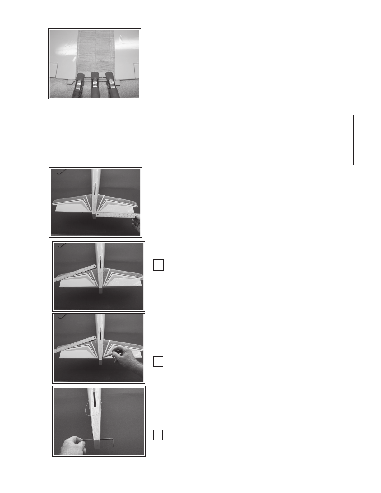
Clamp Wing Panel:
The lite-ply scraps prevent the clamps from damaging the wing and
also force the top and bottom surfaces to align. Be sure to put one clamp
directly above the wing joint line to assure the surfaces will be flush. Set the
wing aside on the flat surface to cure. You may want to evenly support the
underneath side of each wing tip to help prevent the wing panels from drooping or separating. If you have used the rubberbands and clamps properly
this should not be necessary, but is a good safety precaution. After the
expoxy has cured, check the fit of the assembled wing in the fuselage saddle.
Step 5: Tail Surface Assembly:
Gather together the Vertical and Horizontal tail pieces, 30-minute epoxy, epoxy brush,
T-pins, scale/ruler, Elevator Wire “U-Horn”, felt tip pen, cloth tape measure.
NOTE: The Pull-Pull rudder cable is in place. It is very convenient
to do it now, although it can be done later as well. Hold the fuselage
vertical with the nose down, feed one end of the cable through the hole
provided and let it fall to the wing saddle area. Start with the right-side
hole in the fuselage tail. Make sure the cable crosses in the fuselage
interior so that the cable from the right hole goes the left servo arm. Secure the cable in the saddle area to the fuselage side opposite the side
from which it was fed through the hole. Use masking tape to secure it to
the side. Repeat process from the other hole. Leave the cable “looped” at
the tail as shown to prevent it from accidently being pulled into the fuselage and lost. Do not cut the rudder cable at the tail at this time.
Test Fit and Align Horizontal Stabilizer:
Slide the horizontal stabilizer (HS) into the HS slot in the fuselage
and check for fit and alignment. In particular, check that it is horizontal.
Measure the trailing edge (TE) from the fuselage to the outer edge as
shown and balance each side.
Measure the leading edge (LE) from the fuselage to the corner as
shown. Measure both sides and balance. Iteratively, measure the LE and
TE to perfectly balance each side. This should be sufficient, however, you
may refer to “Supplemental figure 2” for an alternate or additional measurement method to set the HS in place. Check the HS alignment and VS
orthongonality with the wing in place. Adjust the HS & VS alignment to the
wing and fuselage as shown in figures 2 & 3 on page 44.
Mark the HS at the Fuselage Edge:
Using a felt tip pen, mark the HS at four points at the intersection of
the HS and fuselage at the Trailing and Leading edges. Remove the HS (If
the OraCover is not already removed in the mounting area ..... using a
straight edge and a razor blade, score a line in the OraCover about 1/16”
inside the marks you made above. Do this on top and bottom. DO NOT
CUT INTO THE WOOD as it will weaken the HS. Remove the OraCover
between the lines you just made.) Do not destroy the alignment marks you
made above.
Insert Elevator Connecting “U-Horn”:
Insert the elevator connection U-horn (Wire) into the fuselage HS
slot. It should be in the half-circle slots at the rear of the HS slot.
17
Page 18
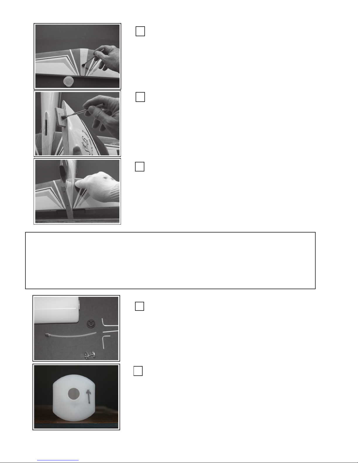
Install Horizontal Stabilizer:
Mix an ample amount of 30-minute epoxy and apply to the HS in
the bare-wood, mounting area. Apply epoxy to both top and bottom.
Slide the HS into place and align to the marks you made previously.
You may wish to recheck alignment then “pin” the HS in place for stability while the epoxy cures. DO NOT apply epoxy to the slot in the
fuselage as it will smear epoxy on the HS as you slide it in place.
Recheck for alignment and “squareness”
Install the Vertical Stabilizer:
After dry fitting the VS and checking for fit and alignment, apply
30-minute epoxy to the “key-lock-tab” and both mating surfaces on the
VS and the fuselage. Apply epoxy in the fuselage key-slot all the way
down to the HS. Slip the VS into place, check again for alignment and
fit and pin in place as necessary. Recheck the HS alignment and VS
orthongonality with the wing in place. Adjust the HS & VS alignment to
the wing and fuselage as shown in figures 2 & 3 on page 44.
Clean-up:
Dampen a cloth with denatured alcohol and clean any epoxy that
may have squeezed out from the joints. Set aside to cure. Set the
fuselage level so that gravity applies equally to all portions of the tail
surfaces and thus does not effect the alignment while the epoxy is
setting up. Check the HS and VS alignment and adjust as necessary.
After the epoxy has cured, re-check the HS and VS alignment and fit.
Step 6: Fuel Tank Assembly:
Open the prepackaged fuel tank components and inventory the parts. Handy tools for
this assembly step are: 1) Dremel© tool with cut of wheel, tubing bender (See supplemental pictures 4 and 5)
Fuel Tank Parts:
The fuel tank parts are: Tank, metal tubes (2), stopper, fuel line,
clunk, front and rear stopper plates, machine bolt. There is a third metal
tube shown that is an optional fill line (not included). Bend one metal
fuel tube as shown (left). This is the vent or “muffler-Pressure” line.
The bend should reach from the stopper hole to just below the top of the
tank. The second straight-tube is for the fuel supply to the engine.
Bend the fill line (if used) to reach near the bottom of the tank.
Mark Fuel Tank Orientation:
Orient the tank as shown (left) and mark an arrow or other appropriate marking to denote the top of the tank. You may also mark the top
of the tank if you wish.
18
Page 19
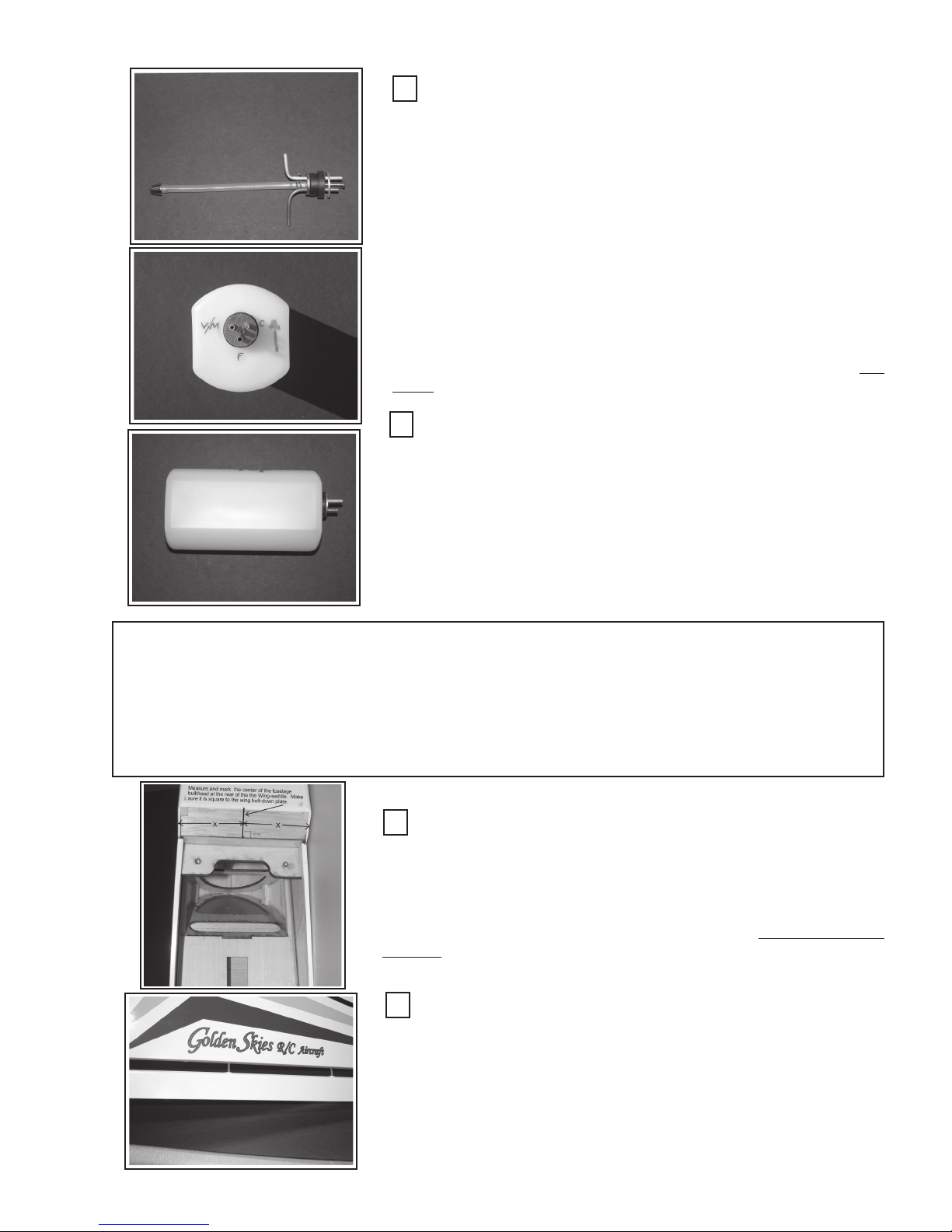
Assemble the Tank Stopper & Fuel Tubes:
The orientation that the “fill”, “Vent-Muffler”, and “Carburetor” tubes
are placed in the stopper holes is a matter of preference. They are generally oriented to provide easy fuel-tubing access to their respective functions within the cowl. A typical arrangement is shown in the picture (below-left). The two tubes that are bent: 1) up (vent), and 2) downwards
(fill) should be near, but not touching, the inside top or bottom of the tank
respectively. Prebend, then slide the tubes through the rear stopperplate, then through the stopper holes, and then slide on the front stopper
plate. Place the bolt through the front-plate, then through the stopper,
and screw it into the rear plate. Do not tighten at this time.
Add the silicon fuel pickup hose to the fuel tube. Add the clunk to
the other end of the hose. The length of the clunk-hose-stopper combination should be such that when the stopper is in place the clunk is about
1/8” short of the rear of the tank. This is to allow the clunk and hose to
move freely as the tank is moved to any orientation. Note that an op-
tional hose retainer-clamp has been added to the fuel pickup hose.
Final Assembly:
Slide the stopper into the tank-neck to check the fit and tube placement. You may want to iteratively adjust the tubing lengths, bends, etc.
to get it correct. Remember to debur any cuts you make to the metal
tubes and do not kink the metal tubes. When satisfied, tighten down the
stopper screw to seal the tank, and be sure to mark what each tube’s
function is on the tank and on the firewall.
The tubes should stick out from the front of the tank about 1/2” to
3/4” to allow ample length to attach silicon fuel tubing. They do not necessarily need to be even in length.
Step 7: Install Control Surfaces:
Gather the Ailerons, elevators and rudder, 30-minute epoxy, toothpicks, mixing cup,
masking Tape (Blue), the wing-bolt brace, clamps to complete the installation of the control surfaces and the wing.
Mark Fuselage Center:
Using a ruler or scale, determine the center of the bulkhead at the
rear of the wing-saddle area. Draw a center-line up the bulkhead as shown
left. Make sure the line is square with the fuselage’s wing-bolt plate. Some
builders like to fiberglass the bottom of the wing where the two wing panels
join. If you wish to do this, complete Optional step “WPFG-1” shown in the
“Optional Assembly Steps” at the rear of this manual”. now prior to pro-
ceeding.
Test Fit and Install Ailerons:
Test each aileron by sliding the hinges into the wing hinge holes. Do
so on each panel. Interchange ailerons as necessary. Mix up sufficient
30-minute epoxy and place in wing hinge-holes as described in step 1.
Reinsert the aileron and check for up and down travel. The hinge gap
should be minimal, parallel, and free to travel.
19
Page 20
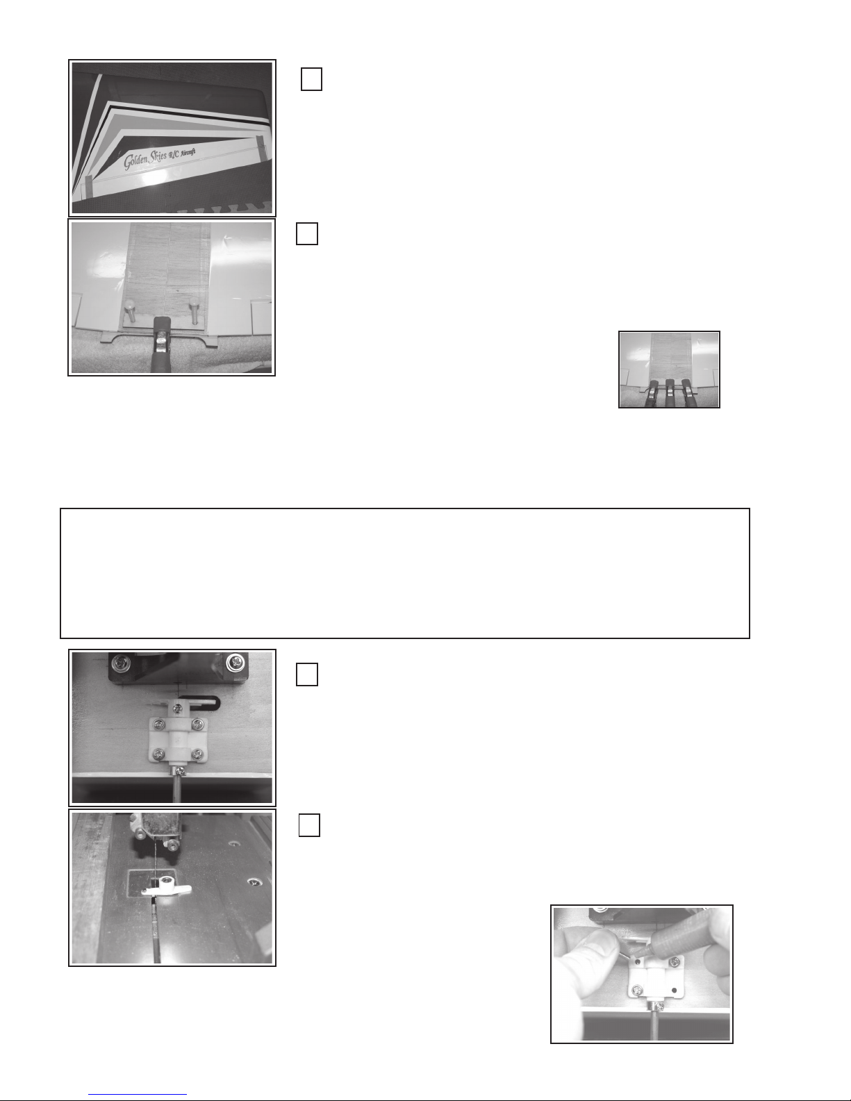
Secure Ailerons:
Secure the ailerons in place with “Blue” masking tape in as many
places as necessary to achieve a good, low-gap, and parallel hinge line.
Repeat the aileron installation process on the other aileron.
Attach Wing Bolt Plate:
Attach the wing-bolt-plate to the wing as shown using 30-minute epoxy. Align the plate using the 1/4” nylon wing-bolts. Clamp in the middle,
remove the nylon bolts, and add two more clamps. Clean any epoxy from
the bolts as necessary.
Complete step 7 by attaching the elevators and the rudder to the horizontal stabilizer and
the vertical stabilizer respectively, using the same technique as used to attached the ailerons.
Allow time for the epoxy to cure. Be sure to epoxy in the U-horn to the two elevator halves.
Step 8: Nose Wheel Assembly:
Open the nose wheel assembly package. You will need: 1) nose landing gear assembly, 2) Locktite ®, 3) # 2 phillips-head screwdriver, 4) Plastic push-rod and guide
sleeve.
Assemble the Nose Wheel Mount:
Assemble the nosewheel mount, control arm, wire landing gear and
collar to the fire wall as shown (left). Note the ‘tab’ on the main mountbracket is faced down. Mark the control arm on the left (as facing the
firewall, the one NOT in the push-rod hole area). You will be removing this
arm so take care in noting which one to cut off. The wire nose gear should
be flush with the top of the control arm.
Cut off the Nose-wheel Control-Arm:
Cut off the control-arm you marked in the step above using a saw,
diagonal cutter, or other tool as necessary. Smooth off the kerf to prevent
it from catching on anything. Reassemble using Locktite ®.
20
Page 21
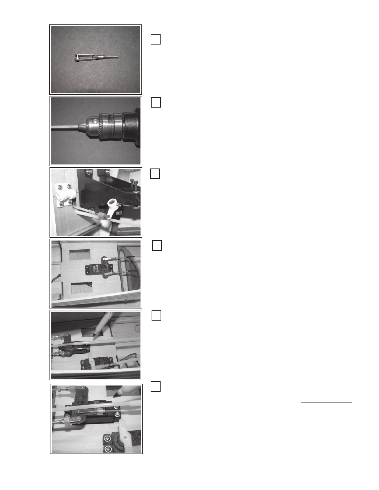
Measure Clevis and Threaded Connecting Rod:
Thread the fully threaded connecting rod into the clevis so that about
1/4” is showing in the clevis area as shown. Using an electric drill, chuck
the threaded rod into the drill chuck to about 3/16” - 1/4” from the base of
the clevis.
Thread the Connecting Rod into Plastic Push-Rod:
Remove the clevis. Add a drop of medium CA glue to the hole in one
end of the plastic push-rod. Holding the plastic push rod in one hand and
the drill in the other, thread the rod into one end of the plastic push-rod.
Run the connecting rod into the push rod until the drill chuck shanks-out.
Assemble the Nose Gear Push-rod:
Place the push rod into the its plastic guide sleeve. Dress the sleeve
through the control arm hole in the firewall, and rearward into the wing
saddle area. Be sure not to dress the sleeve through the opening where
the fuel tank will be installed. Attach a 3/16” length of fuel tubing on the
clevis as a safety closure retainer. Screw the clevis onto the threaded rod.
Reassemble the wire nose gear, the control arm and orient the wire nose
gear to a neutral or straight forward position. Tighten the set screw in the
control arm.
Install Rudder Servo:
Install the rudder servo as shown. Although not necessary, it is
prudent to ‘scab-on’ a piece of 1/8” lite-ply under the servo tray in the
area of the servo screws for extra strength. Lightly predrill the servo
screw holes with a 1/16” diameter bit. Install the servo with the servo-arm
facing toward the tail, and screw in place using the screws provided by
the servo manufacturer.
Cut Sleeve to Length:
Lay the sleeve/push-rod over the rudder servo arm as shown. However, prior to marking and cutting, slip on the lite-ply sleeve braces and
secure the sleeve to accommodate and allow for the receiver, battery, wing,
and fuel tank. You may want to dry fit these items in place as you make the
final decision about the placement of the sleeve braces. Once finalized,
and the braces have been glued in place, mark the sleeve as shown. Remove push-rod and cut off the sleeve. Replace the push-rod.
Mark and Cut Push-Rod:
Place the clevis and connection rod into the servo arm. Mark the
location where the push-rod will be cut off. Be sure THE WIRE NOSE
GEAR IS IN THE NEUTRAL POSITION. You will have ample adjustment
capability by adjusting the clevises on the connecting rod, but you should
get the mechanical center set up here. Thread the connecting rod into the
push-rod as in the step above. You may want to remove the push-rod from
the sleeve to do this, or, you may have enough flexibility in the sleeve to
do it in place. This depends upon how you set up the sleeve braces.
Reassemble, check for proper movement, centering, and that the
sleeve-push-rod combination does not flex during the steering operation.
21
Page 22
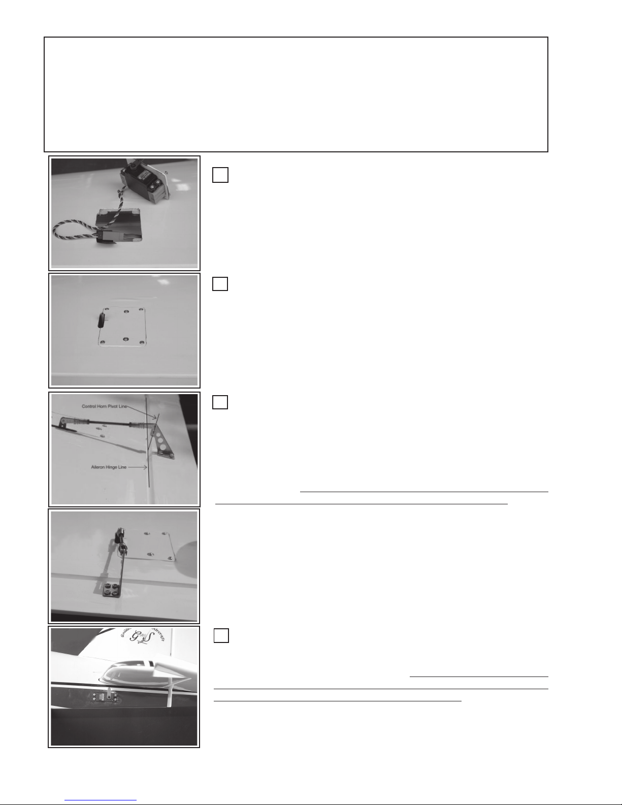
Step 9: Install Servos, Horns & Push-rods:
(Aileron, Elevator, Rudder) Gather together, all Servos, Control linkages (Push-Rods
& Clevises (3 ea sets), Pull-Pull hardware, Control Horns, etc). You will need 1) Drill & 1/
16” bit, # 2 Phillips head screwdriver, locktite®, CA glue, ruler, felt-tip pen.
Install Aileron Servo:
Attach the servo wire to the servo extension cable and secure the
connector with a piece of electrical tape. (Optional: Heat shrink tubing
also works well for securing the connectors together.) Dress the wiring
into the wing servo box and pull out the extra cable, via the hole at the
wing root.
Attach Servo to Servo Wing Box:
Insert the servo-cover plate into the servo box as shown. Predrill the
four corners about 1/4” in from each edge, using a 1/16” bit. Remove the
servo-cover and pretreat the holes with thin CA (do not glue the plate to the
servo box). Reinstall the servo-cover and install the supplied attachment
screws. Finally, predrill the cover plate where the hardwood blocks are
attached, treat with thin CA and install the screws with the attached washers.
These screws are “safety” retainers in the event the epoxy should loosen.
Install Aileron Control Horn and Push-Rod:
There are two alignments that must be made to install the aileron
push-rod: 1) Align the horns’ vertical arm in a straight line with the servo
arm and 2) align the control arms pivot point (the three, nylon bushingholes in the control arm) with the Aileron Hinge Line (see two pictures at
left).
Attaching the push-rod may assist you in making and holding this essential alignment. Be sure the servo arm is centered, i.e. perpendicular to
the wing surface and the aileron is in the neutral position (tape it).
Mark and drill pilot holes in the four locations to mount the aileron
control horn. Use a 1/16” bit and drill to about 1/8” depth. Generously treat
the holes and surrounding area with thin CA glue. Allow to dry. Attach the
control horn using the screws provided.
Attach the push-rod and adjust for mechanical center. Tighten the
locking nuts up to the clevis base and apply drop of locktite® to the pushrod threads just behind the locking nuts. Be sure the clevis retainer springs
are in place and secure.
Repeat process for the other aileron.
Install the Elevator Servo:
Dress the 24” elevator, servo extension-cable through the elevator
servo hole and into the wing-saddle area. Attach the servo to the cable and
secure the connector using electrical tape. (It is prudent, but not required to
place a small piece of 1/8” Lite-ply behind the servo hole where the screws
attach and secure with CA glue for extra screw strength.) Attach the elevator servo with the servo arm centered and up as shown left. Follow all servo
manufacturers’ installation recommendations.
22
Page 23
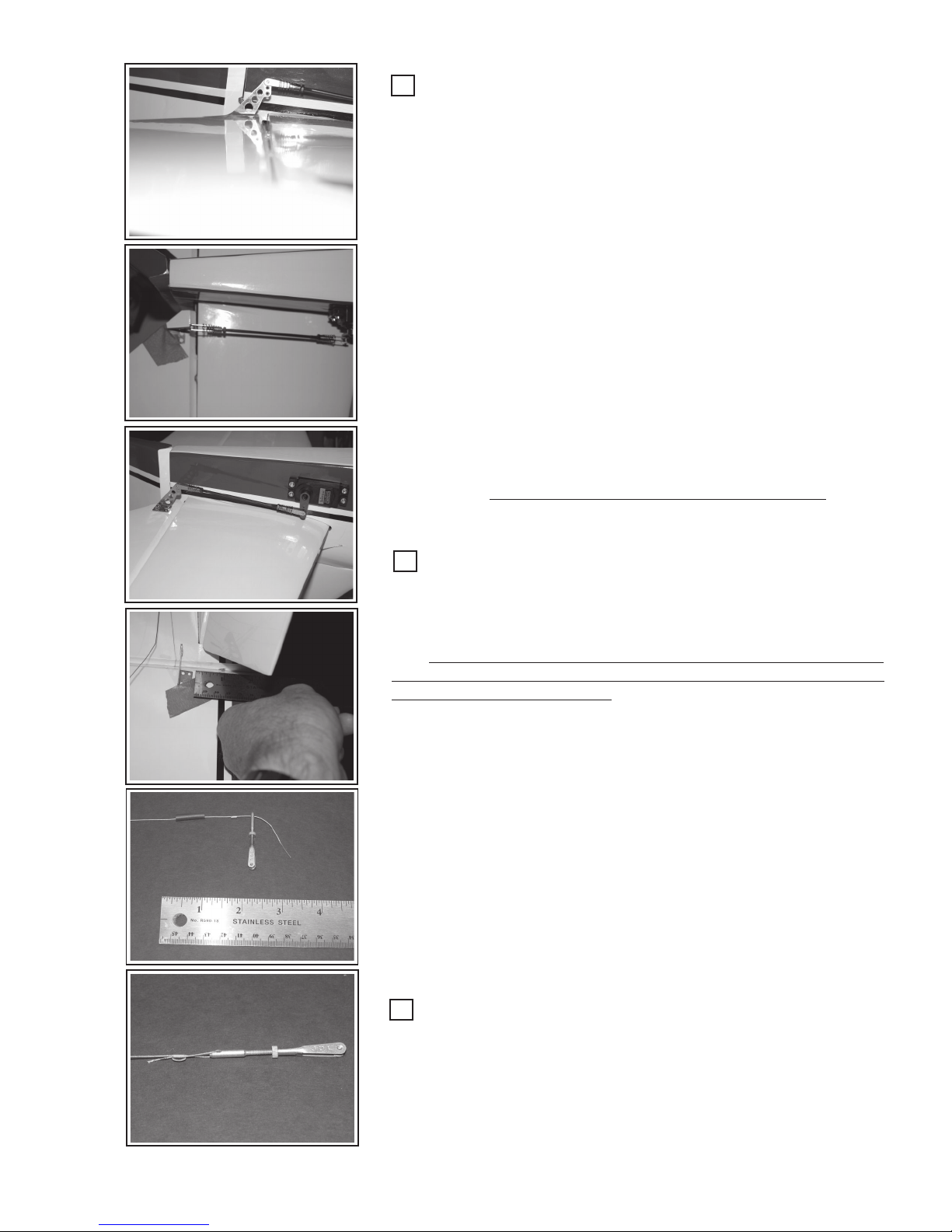
Install Elevator Horn & Push-Rod:
Like the aileron horn alignment , the elevator horn requires two
alignments, 1) With the elevator hinge line and 2) in straight line with the
elevator servo-arm. Again, using the elevator push-rod and a piece of
blue masking tape, may help you align the elevator horn. Be sure the
elevator and the servo-arm are both in the neutral position.
Mark and drill pilot holes in the four locations to mount the elevator
control horn. Use a 1/16” bit and drill to about 1/8” depth. Generously
treat the holes and surrounding area with thin CA glue. Allow to dry and
attach the control horn with the screws provided.
Attach the push-rod and adjust for mechanical center. Tighten the
locking nuts up to the clevis base and apply drop of locktite® to the pushrod threads just behind the locking nuts. Be sure the clevis retainer springs
are in place and secure.
Check the servo-arm movement and the corresponding elevator
movement. Throws will be discussed later.
Adjusting for the greatest “volume” of movement is done by attaching the push-rod close to the pivot point of the elevator servo and at the
top point of the control horn.
For greater sensitivity and control throw, do just the opposite. Attach the push-rod at the tip of the servo-arm and at the bottom of the
control horn. Take care with this high-sensitivity arrangement. Unless
you are a highly experienced pilot, this arrangement may be too sensitive for you and cause you to crash. (See Control Throws)
Install the Rudder Control-Horns (2 ea):
Dress the pull-pull cables such that there is an equal length of cable
feeding through to each side of the rudder. Cut the loop in the cable at
the tail so that you now have two distinct cables. Remember that these
cables are to cross each other in the fuselage.
Take note that the two rudder control-horns are set at slightly different heights on each side of the rudder to prevent the mounting screws
from interfering with each other.
Using a ruler, measure 2-3/4” up from the bottom of the rudder to
the bottom of the rudder control-horn to set the position of the controlhorn on one side of the rudder.
Measure 2-7/8” up from the bottom of the rudder to the bottom of
the control-horn to set the position of the rudder control-horn on the opposite side of the rudder.
The rudder horns requires two alignments, 1) With the rudder hinge
line, and 2) in height above the bottom of the rudder as described above.
Again, using a piece of blue masking tape, may help you align hold the
rudder horns in place while marking to drill pilot holes.
Mark and drill pilot holes in the four locations to mount the rudder
control horn. Use a 1/16” bit and drill to about 1/8” depth. Generously
treat the holes and surrounding area with thin CA glue. Allow to dry and
attach the control horn. Adding a bit of medium CA glue to the hole prior
to inserting the screw will help secure the screw.
Build the Pull-Pull Cable System:
Starting at the rudder end of the cable, thread the cable through the
copper clamp-tube and through the threaded clevis-rod. Loop back into
the clamp-tube and then re-loop back around and through the tube as
shown. Note there is an optional piece of shrink-tubing on the cable just
to “pretty-up” the final assembly. You will need a pair of needle nose
pliers to make the final cable penetration of the tube. Arrange the tube to
be 1/4” to 3/8” away form the clevis-rod and tighten up the cable loops.
23
Page 24
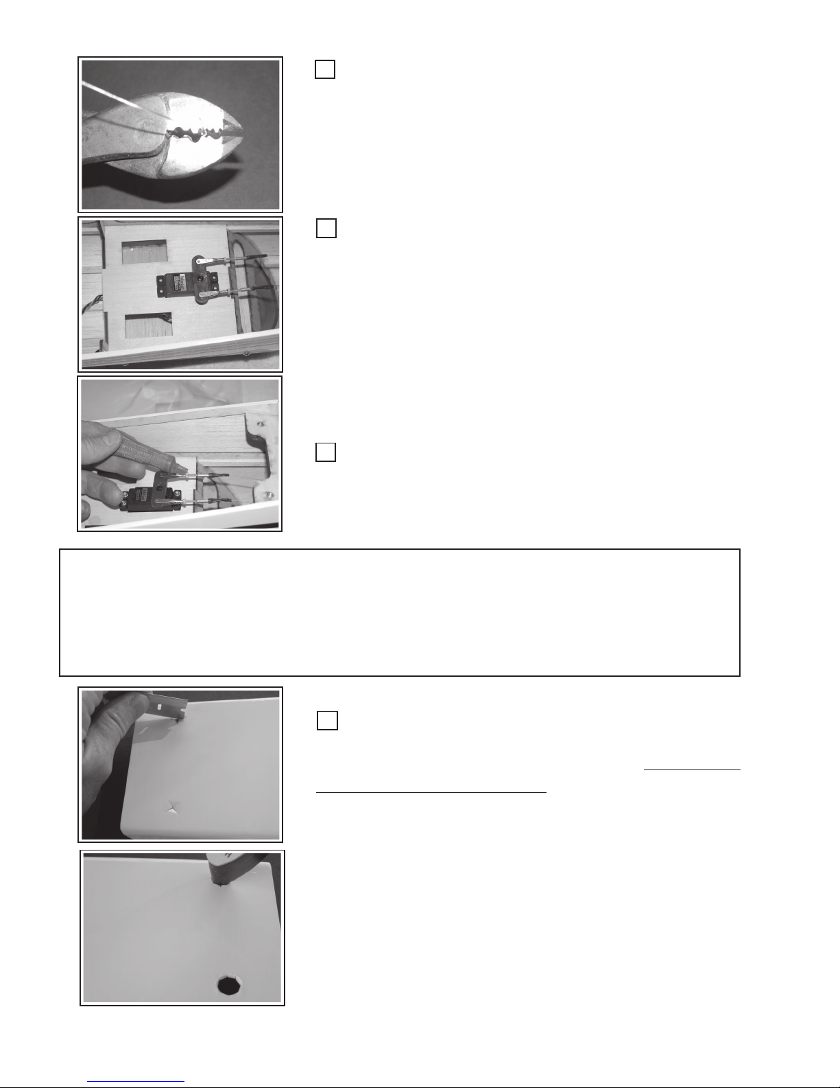
Crimp the Tube:
Crimp the copper tube using either a crimping tool or pliers. Take
care not to over crimp the tube and split its sides. Test for security and
strength. Slide on and shrink the optional heat-shrink tubing if used.
Attached the clevis to the rudder control horn.
Repeat this process for the opposite side rudder cable.
Assemble the Pull-Pull Cables to the Rudder Servo
(Be sure you have electrically & mechanically centered the servo/
arm with the radio’s rudder “stick”, trims, sub-trims and centering at
neutral.)
Lock the rudder into a neutral position using masking tape. Attach
the rudder clevises to the rudder servo arm. Be sure the servo arm is
either metal or very strong plastic. Thread each pull-pull cable as before and iteratively dress, arrange and tighten the cables as shown left.
Be sure to keep the servo-arm and rudder in a neutral position.
Also leave enough threads on the connectors to allow for ample adjustment and tensioning of the cable when the assembly is finalized. Tighten
the knurled locking nuts against the clevises at each end (4-places).
Secure the Locking-nuts:
Secure the locking-nut with a drop of locktite®. Test the entire
system for strength, freedom and range of movement, centering, etc.
Make any adjustment as needed.
Step 10: Install the Belly Pan:
Items needed are: 1) Wing ... attached to the fuselage, 2) Belly-pan, 3) 30-minute
epoxy, 4) Clamps, 5) rags and denatured alcohol, 6) Wing bolts, &) razor blade, 7)
covering iron, 8) Clear, fuel proof spray.
Prepare the Belly Pan for Attachment:
See and complete (if desired) the optional
assembly step “WPFG-1” on page 34 prior to installation of the belly pan.
Cut a “star” pattern in the covering over the two wing bolt holes in
the belly-pan.
Using a covering iron’s outside tip, secure the covering to the
inside edge of the wing bolt holes in the belly pan.
24
Page 25
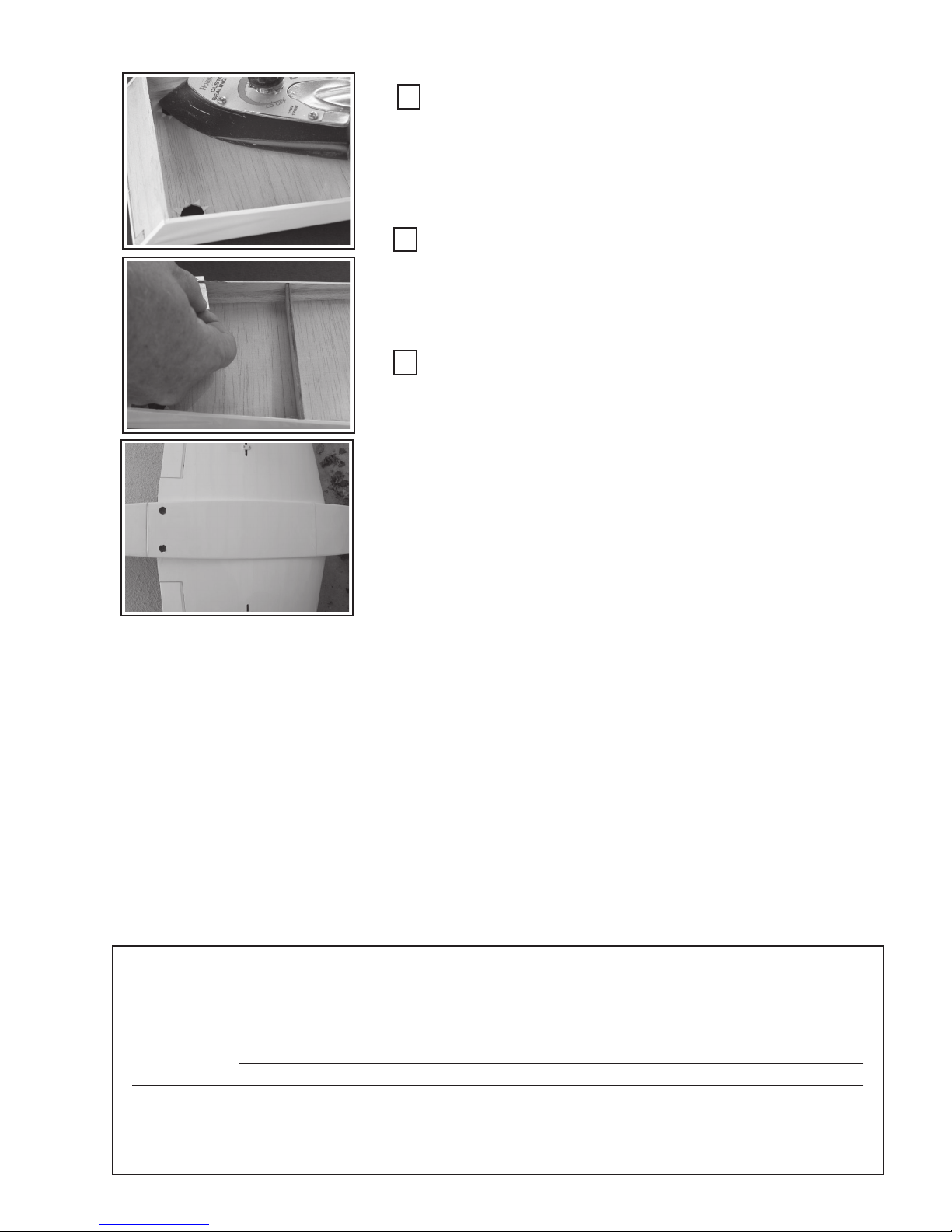
Turn the belly-pan over and secure the tips of the covering to the
underside of the belly-pan. Spray the entire belly-pan underside with a
clear, fuel proof spray paint. Do not over-soak the wood as warpage
may occur. Colored paint may be used, but take care not to get any on
the outside of the belly-pan.
Trim Covering from Edges:
If there is covering material on the belly-pan edge where it will be
secured to the wing bottom, carefully remove the covering with a razor
blade.
Attach the Belly-Pan (BP):
Attach the wing to the fuselage using the two nylon wing-bolts. The
wing-bolt holes should already be drilled in the wing and in perfect alignment with the mating blind-nuts. If not, secure the wing in its correct
position. (See joining the wing panels and/or optional figure # 2) Drill the
holes and attach the wing using the 1/4” nylon bolts.
With the fuselage up side down, place the BP in place and check
for fit and alignment. It should align evenly with the fuselage edges and
the bottom wing surface. Depending upon the humidity in your location
and how heavily you sprayed the belly-pan interior, you may see some
BP warpage or miss-alignment. The BP is light and flexible and will
conform to the wing surface with slight pressure. Gently reshape or sand
where necessary to obtain the proper fit.
Mark the BP position at the leading and trailing edge on the wing
surface so that you may relocate the pan after removal, and also for
removal of the wing covering material under the BP.
If you performed the OPTIONAL under-wing fiberglass step, then
you have already removed the wing covering under the belly pan. If not,
using a straight edge, cut the covering just 1/32” inside the marks you
made above. This is the same as you did on the horizontal stabilizer.
Take care not to cut the balsa wing bottom ........ go lightly! Remove the
covering material from leading to trailing edge. (It is a good ideal to give
this bare wood area a light dusting of clear fuel proof spray.)
Apply 30-minute epoxy to the BP edges and place the BP back on
the wing. Tape and/or clamp as necessary to secure the BP until the
epoxy cures. (You may want to remove the wing from the fuselage to get
a better clamping capability. With 30-minute epoxy, you should have
time to do this.)
When finished, remove the wing from the fuselage.
Step 11: Fuel Tank Installation:
You will need: 1) Fuel Tank (previously assembled), 2) Scrap 1/8” lite-ply, 3) foam
rubber, 4) Silicon (RTV) caulking.
NOTE: As a precaution against the damage that fuel can cause to wood, you may
find it advisable to spray the interior of the fuel tank compartment with clear, fuel proof
paint. Fuel soaked wood will quickly cause glue-joint and wood failures.
25
Page 26
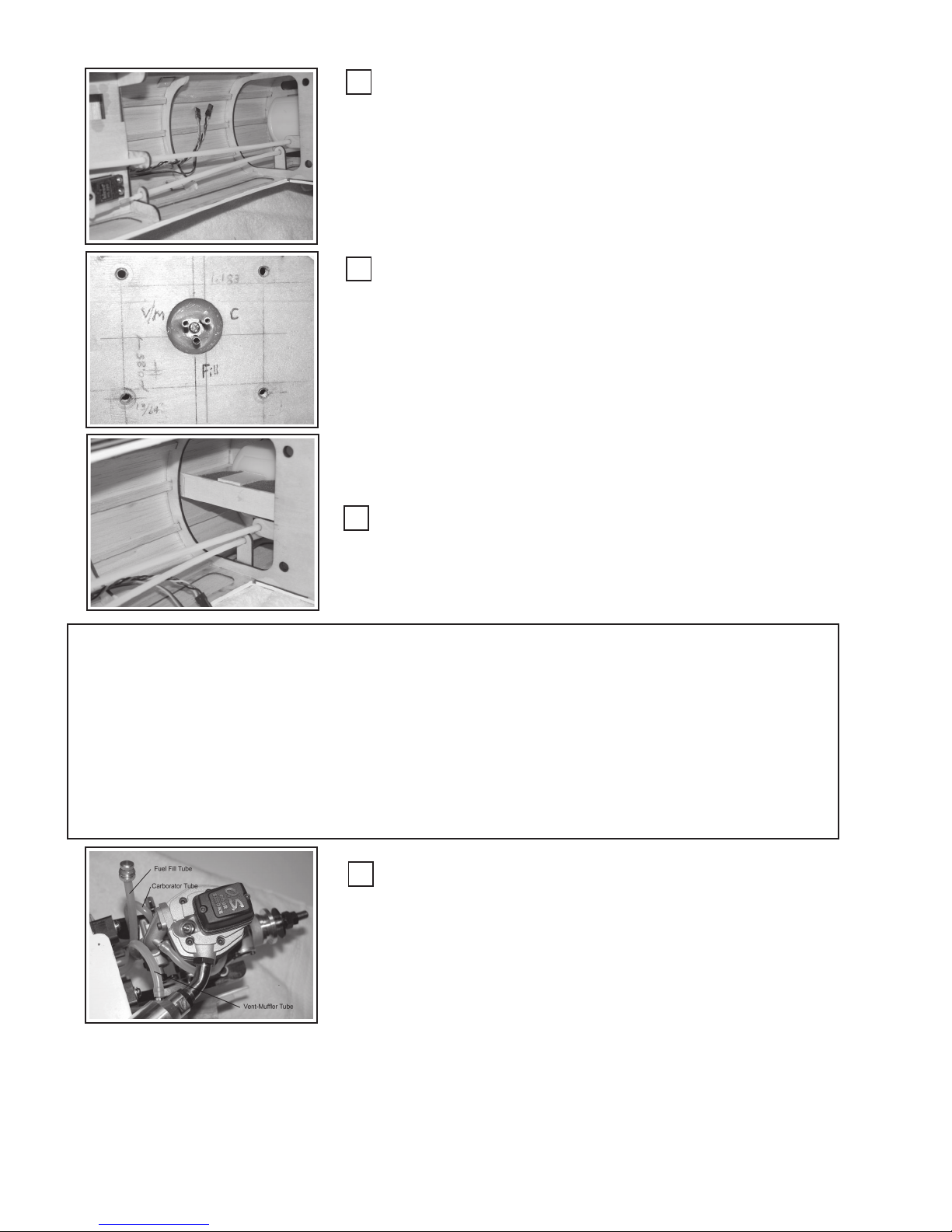
Install Fuel Tank:
Slide the fuel tank into the forward fuselage area such that the front
tubes protrude through the firewall in the round hole provided. Orient
small pieces of foam rubber between the tank sides and fuselage former
(F2) to cushion the tank from vibration. (Window sealing foam, that comes
in various width, adhesive backed strips, is available at your local hardware store. Glue the strips to the inside hole in former F2 and then slide
in the tank.
Seal the Tank at Fuselage:
You should have previously coated the inside of the firewall tank
opening with 30-minute epoxy to protect the hole edges from the effects
of fuel. Using RTV-Silicon sealer/caulk, seal the joint between the fuel
tank the firewall. If you use your finger, wet the tip of your finger to
minimize the silicon from sticking to your finger. Form a bead of sealant
all the way around the tank and firewall intersection.
Reattach the engine mount using locktite® on the mounting bolt
threads and securely fasten down. Note on the picture (left), the horizontal lines just inside of the mounting holes are the placement of the inside
edge of the mounting rail and matches your engine crankcase width plus
~ 0.05” (~3/64).
Brace Fuel Tank:
Using a scrap piece of balsa or lite-ply, form a brace as shown left to
prevent the fuel tank from sliding backwards. Many different brace arrangements will work. The one shown (left) is easy and effective. Wedge
a piece of foam rubber between the brace and the back of the tank.
Step 11: Install the Engine:
The following illustrations will show the installation of a OS-91FS ® 4/stroke engine.
You may choose to install the engine of your choice. The process will be similar where the
biggest differences will be the throttle push-rod routing and muffler installation. You will
need: 1) engine, 2) mounting bolts (# 6-40 minimum), 3) locknuts, 4) screwdrivers and/or
nut drivers, 5) Needlenose pliers, 6) Plastic, throttle push-rods, 7) CA glue - medium, 8)
fuel tubing,
Install Fuel Tubing to Engine:
Reattach the engine. Only two bolts in opposite corners are necessary at this time, as you will shortly remove the engine to install the cowl.
Cut three pieces of silicon fuel tubing at the correct length to reach from
the fuel tank ports to their respective functional locations on the engine:
1) Carburetor
2) Vent/Muffler
3) Filler cap (optional), Notice that an optional fuel filler line has
been installed and terminated with a “filler-cap”. (Available at
your local hobby store or at the GSRC website .....
http:// www.goldenskiesrc.com)
You do not need to attach the tubing to the engine, as you will be
removing the engine to install the cowl. (Shown attached for clarity)
26
Page 27
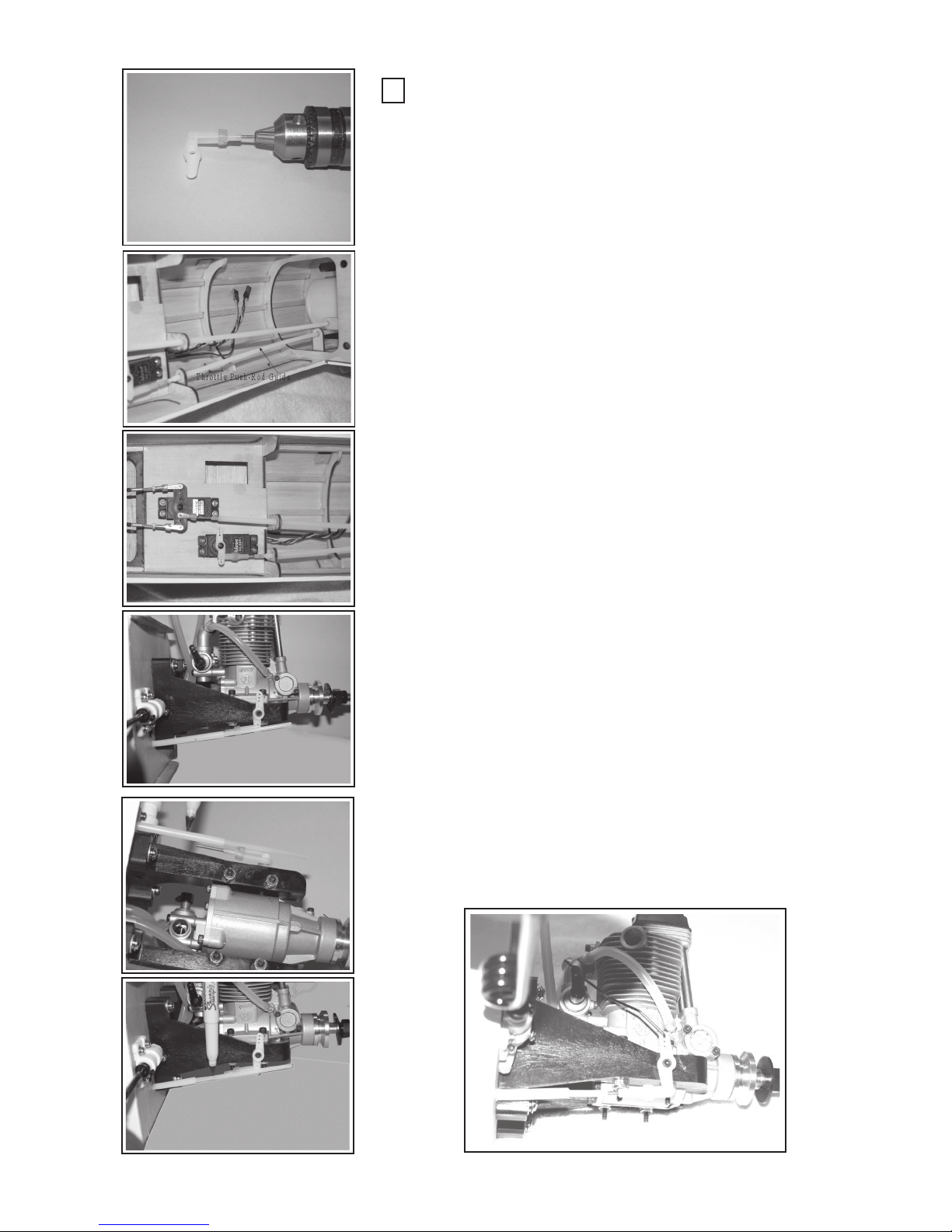
Install the Throttle Push-Rod:
Locate the remaining plastic Push-rod and guide sleeve. Depending upon the engine you choose to use, you may be able to run the pushrod directly from the throttle servo to the carburetor control-arm. In the
case of a 4/stroke engine you may need to set up a bellcrank to access
the rear-mounted carburetor. The two procedures are identical except
for the secondary bellcrank.
Using the two, fully-threaded metal connecting studs and an electric
drill, screw ~ 3/8’s of the stud length into the push-rod. Do one end only
at this time. Thread the nylon clevis on one end.
Install the throttle servo as shown (left) using the hardware provided
by the servo manufacturer. If you like, glue (medium CA) a small piece
of 1/8” lite-ply to the back of the servo tray where the servo screws will be
inserted for extra strength. Place the throttle servo arm in the neutral
position.
Drill a 13/64” hole in the firewall if the one provided is not suitable
for your engine setup. Note the best place to dress the push-rod guide in
the fuselage and around the fuel tank. Take care not to hit the fuel tank.
Slip the plastic throttle push-rod guide through the firewall hole and up to
throttle servo. Add the lite-plywood support brackets to the guide as shown
left. Attach the plywood brackets to the formers as shown and be sure the
guides do not interfere with the wing, (i.e. place them above the wing saddle).
If using a secondary bellcrank (an extra servo arm will work well),
drill the engine mount rail (shown left) and mount bellcrank with a screw.
Use washers to space the bellcrank as needed. Locktite® the screw in
place.
Slide the push-rod in the guide from the servo end and attach the
clevis to the servo arm. Lay the push-rod over the carburetor-arm or
bellcrank. Mark the guide tube near the carburetor-arm or the bellcrank
(as appropriate) for length. Remove the push-rod and cut the guide at
the mark. Reinsert the push-rod.
Attach a clevis to the carburetor-arm or bellcrank and lay the push-
rod and clevis in the proper line with each other....(left). Mark the push-
rod for length and cut.
Screw the threaded stud into the push-rod and then the clevis onto
the thread stud. Adjust the clevis by threading it in or out as necessary to
place the clevis at the carb-arm or bellcrank while the arm or bellcrank is
in the neutral position. Remember to keep the throttle servo arm in the
neutral position at all times.
If using a bellcrank (4/stroke engine), bend a wire push-rod connector between the bellcrank and the carburetor-arm.
27
Page 28
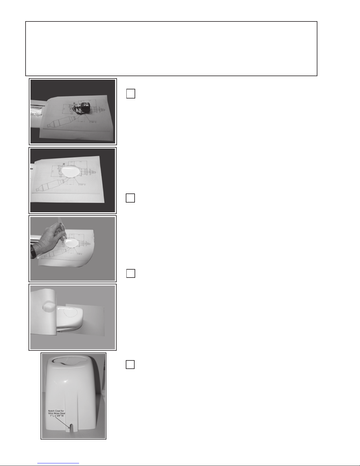
Step 13: Install the Cowl:
You will install the cowl by cutting a hole in the cowl that is specific to your engine,
muffler and way you mounted the engine to the firewall. You will need the cowl, masking
tape, Dremel tool w/cutting disk & sanding drum, ruler, cowl mounting screws.
Locate Hole in Cowl for Engine Head:
It will be necessary to cut a hole in the cowl for the engine head to
protrude outside the cowl. Rather than guessing at the hole center, making
a small hole then gradually and iteratively enlarging it, GSRC will suggest
a more methodical approach using a paper template.
At the back of this assembly manual we have provided full scale
drawings of the two popular engines. Choose one, or use your engine’s
instruction manual which may have a line drawing of your engine. Enlarge
the drawing to full scale using a copy machine. (Shown left is a full scale
drawing of the OS-91FS 4/s engine.)
Cut a hole in the paper template about 1/8” outside the outer dimensions of the head and place the template hole over the engine head. Iteratively adjust the hole size for good head clearance. Tape the paper template in place on the fuselage.
Transfer Template Pattern to Cowl:
Fold the template back, out of the way at the tape point, and remove
the engine. Place the cowl back on the fuselage and measure the distance
from the firewall front surface to the front outside cowl edge to be 5-7/16”.
Secure the cowl with masking tape. You will have to notch the cowl area
where the nose gear extends into the cowl. Be sure the cowl is relative
straight.
Lay the template back over the cowl and trace the hole opening onto
the cowl surface using a felt tip pen.
Check Tracing:
Fold the template back and forth to check the traced line to be accurate within the template hole.
Notch the cowl for nose gear clearance:
Make a notch (3/8” wide x 1.25: long) in the cowl bottom for the
nose landing gear.
28
Page 29
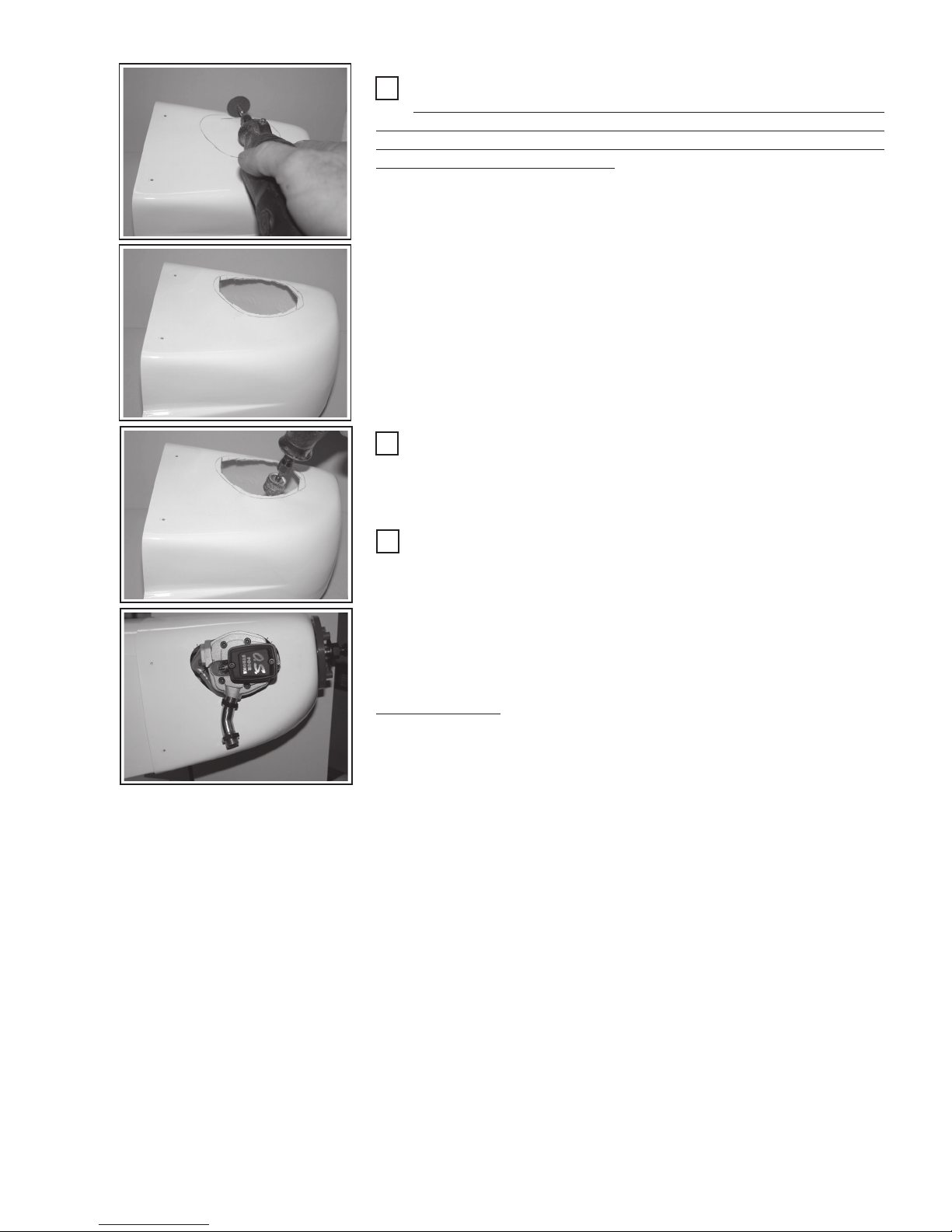
Cut Rough Cowl Engine-Head Hole:
For the following and all power-tool cutting and sanding activities,
wear protective eye wear and a dust mask. Perform the cutting and sanding operation in an open area where the dust will not settle on the engine,
plane, or other dust sensitive parts.
Remove the Cowl from the fuselage. Using a Dremel© tool and a
cutting disc (or other cutting device), cut a rough hole in the Cowl about
1/8” inside the traced line.
Finish Out Hole Size:
Using a Dremel© tool and a 60 grit, 1/2” sanding drum, sand the rough-
out hole to the traced line.
Test Fit the Cowl:
Reinstall the engine and slip the cowl back in place. Install the spinner back plate and adjust the cowl to be about 1/16” back of the spinner
backplate. Observe the cowls position for proper alignment with the lines
of the fuselage.
Check the engine hole clearance. There should be about 3/32” to 1/8”
clearance all around the engine head.
Mark any areas where the hole needs to be enlarged. Remove the
cowl and enlarge the hole in the areas as needed. Do this iteratively, a
little bit at a time to not error and make the hole too big.
Similarly measure and mark any other holes required:
1) Needle Valve and or extension
2) Muffler Ports
3) Fuel filling port, if used. (A fuel filling port is more than conve nient for filling the fuel tank, especially since you can not easily
get to the fuel tube inside the cowl.
4) Vent/Muffler tube
When satisfied, place a 1/16” scrap of balsa between the spinner
backplate the front of the cowl and slide the cowl up to the balsa spacers.
Mount the cowl with the four screws provided. Take time to mark the firewall
location and screw into the firewall where possible.
Install the muffler and vent/muffler silicon tube.
If you do not use a auxiliary fuel filler, route the fuel line from the tank
to the outside of the cowl, back into the cowl and then to the carburetor.
Allow about one (1”) inch between coming out of and going back into the
cowl to cut the tube and place in either a metal coupling tube of better yet
a fuel filter. This arrangement will provide for a inlet, fuel tank filling port.
29
Page 30
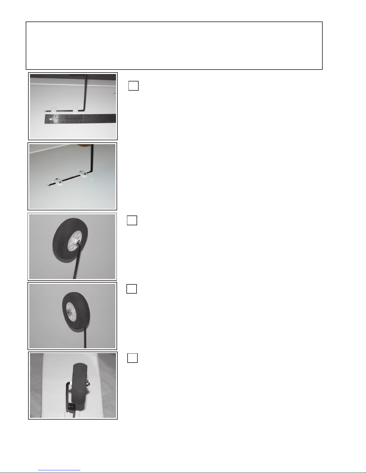
Step 14: Wheel & Landing Gear Installation:
Gather the main landing gear, wheels, wheel collars, stand-off bushings from the
wheel assembly package. You will need: 1) # 2 phillips head screwdriver, drill and 1/16”
Install Wing Landing Gear:
From the landing gear assembly package, gather the wing landing
gear wire (2), the retainer straps (4) and screws (8).
Lay a soft cloth on your work surface and place the wing, up-side-
down on the cloth.
Insert the wire gear into the wing gear blocks. It will only go one way.
Place the nylon retainer-straps across the gear as shown, (left) about 1/2”
in from each end.
Mark the screw holes, remove the gear a drill 1/16” pilot holes ~3/16”
deep. Apply thin CA glue to the holes. Replace the gear and attach the
retainer-straps using the screws provided.
Repeat for the other wing panel.
Install Wing Wheels:
Install Wing Wheels:
Place the plastic wheel bushing on the landing gear axle until it stops,
Place the plastic wheel bushing on the landing gear axle until it stops,
and then put the wheel on.
and then put the wheel on. If the bushing or wheels are tight on the axial,
sand the axial with 180 sandpaper to fit.
Secure Wheel:
Slide the wheel axle collar on the axle and position such that the
wheel is equally distant from the collar and the bushing..... 1/32”. Rotate
the collar set screw to face the rear of the aircraft and tighten down with a
phillips screwdriver.
Repeat for all wheels
30
Page 31
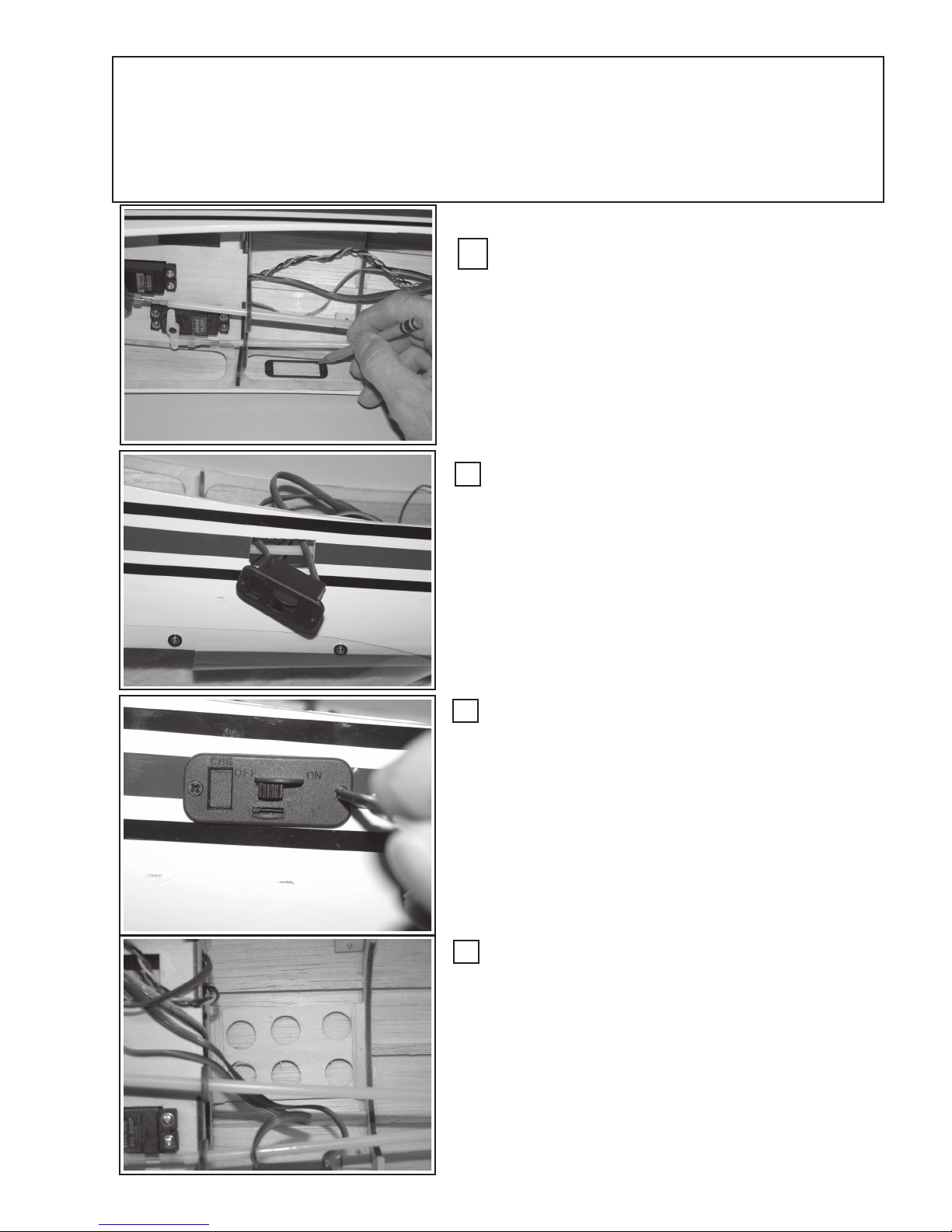
Step 15: Install Receiver, Battery & Switch:
You will need a 4 or 5 channel receiver; 4.8 or 6.0 Volt, 1100 mAh battery and a
electrically compatible switch; Velcro strips, Foam Rubber, rubberbands, # 11 blade.
Install Battery Switch:
Install the switch on the fuselage side opposite the
muffler discharge. Generally, this will be the left side. Using
the switch backplate, mark the switch outline location on
either inside or outside of the fuselage; whichever is more
convenient.
Cut a hole in the fuselage where you have marked the
outline. (Double-up or backup the fuselage side with 1/16”
scrap balsa if you wish.)
Attach Switch:
Thread the switch leads through the hole and position
the switch so that the “ON-function” would be forward., (i.e. to
turn the switch on, slide the switch handle forward)
.
Attach Switch:
Place the switch backplate in place and screw the
switch into position using the hardware provided with the
switch.
Install the Receiver Base:
Installation of a “Receiver-Base” is optional as the
receiver may be attached in several different ways to the
fuselage skin or bulkheads.
Using a “lightened” scrap piece of 2” x 2-9/16” lite-ply,
glue it to the 1/4” stringer and F3 and F4. as shown left.
Attach two strips of Velbro© to the receiver base.
31
Page 32
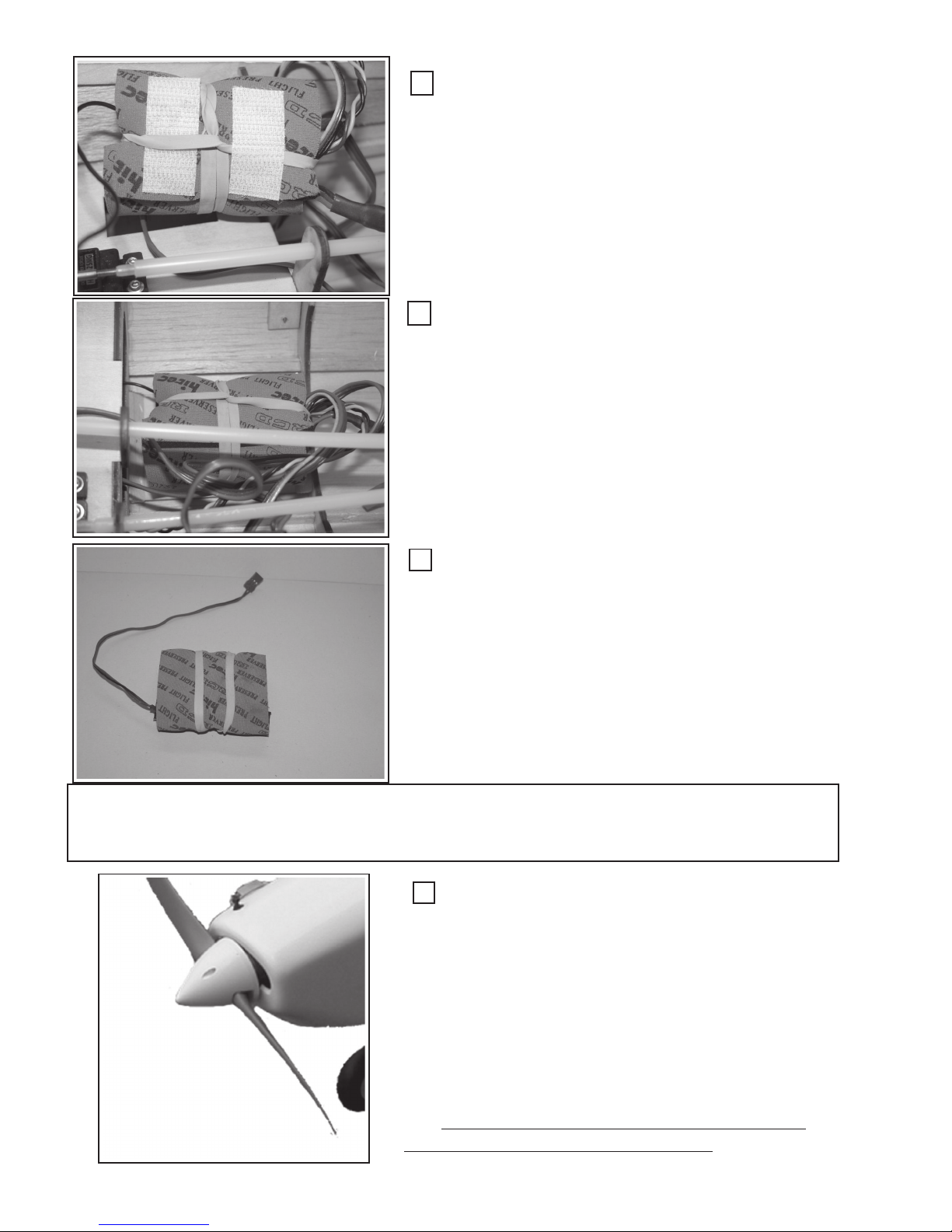
Foam Wrap Receiver:
Attach the servo and switch wires to the receiver, then
wrap your radio receiver in the foam provided by the receiver
manufacturer. Secure with a rubber band and attach Velvro©
to the bottom, as shown.
Attach receiver:
Attach the wrapped receiver to the Velcro© on the
receiver backplate. Dress the servo wire loosely relative to
each other but securely such that they do not move around
as the airplane is maneuvered in the air.
Spinner Installation
Install Battery:
Install Battery:
Wrap the battery in protective form and secure with
Wrap the battery in protective form and secure with
rubberbands. The battery will be placed in the fuselage in
rubberbands. The battery will be placed in the fuselage in
such a position to assist the proper pitch balance. Generally,
such a position to assist the proper pitch balance. Generally,
the battery will be placed under the servo tray. But this
the battery will be placed under the servo tray. But this
depends upon the engine you use and other weight distribu-
depends upon the engine you use and other weight distribution factors. Connect the battery plug to the switch. Never let
tion factors. Connect the battery plug to the switch. Never let
the battery float loosely in the fuselage as it is heavy and with
the battery float loosely in the fuselage as it is heavy and with
aerobatics the battery connector will pull loose, and your
aerobatics the battery connector will pull loose, and your
aircraft will crash.
aircraft will crash.
Attach Spinner:
Place the spinner backplate, using the correct spaceradapter, to fit you engine’s propeller shaft on the engine.
Adjust the spinner’s propeller openings to fit your propeller.
Take care, adjust it in a totally smooth line. If you nick, gouge,
or cause any other non-smooth cut, do not use the spinner ....
discard it and get a new one.
Attach the propeller, using your engine manufacturer’s
recommendations and place the spinner over the propeller and
screw it to the base plate. Use the spinner screws provided.
Be sure the spinner seats completely into the baseplate.
Leaving nicks or other discontinuous cut
marks in the spinner is dangerous.
32
Page 33
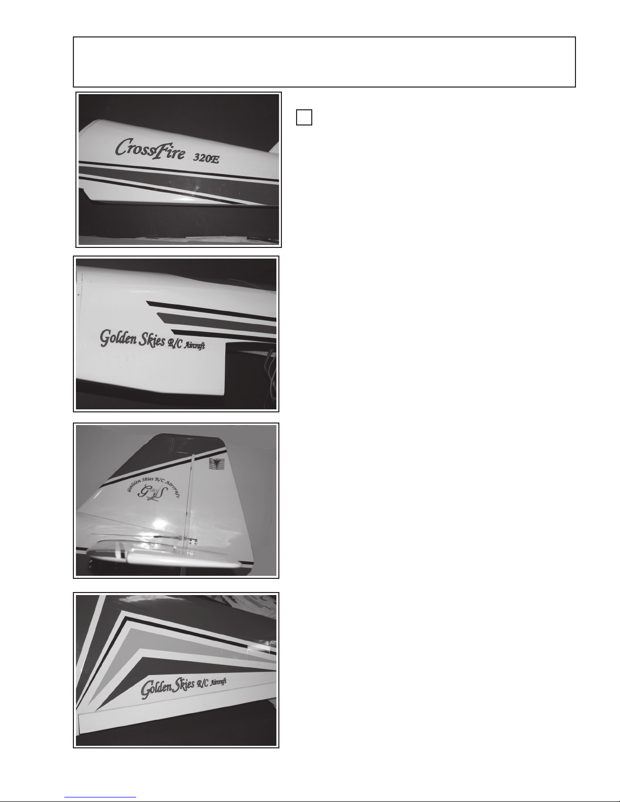
Decals:
Apply the Decals:
Retrieve the CrossFire 320E decal sheet and locate the
specific decals that are placed on the Fuselage-turtle deck,
the fuselage-nose, the tail and the wing as shown in the set of
picture at left.
Separate each decal using a pair of scissors by cutting a
“rough-cut” line between each decal.
Apply the Fuselage-turtle deck decal.
Carefully cut as close to the decal edges to minimize the
amount of clear background area as possible. Cut all the way
around the decal.
Attach the “CrossFire 320E” decal to the fuselage turtle
deck area as shown in the picture above. Start at one end
and lightly touch the decal to the fuselage. Be sure that the
decal is lined-up and straight & parallel with the color strips
just below it.
Using a squeegee or straight-flat-edge, “squeegee” the
decal into place. Work out all bubbles for a clean, flat and
bubble free decal application. Apply to both sides.
Apply the Fuselage-Nose decal:
Attach the nose decal using the same technique as
described above. Be sure to center it such that the decal is
not covered by the wing or the cowl. Apply to both sides.
Apply the Fuselage-Tail decal:
Attach the two tail decals using the technique described
above. Apply to both side.
Apply the Wing Decal:
Attach the wing decal using the technique described
above. Apply to both wings.
(There is an extra “Angle Decal” that may be applied as
you choose.)
33
Page 34
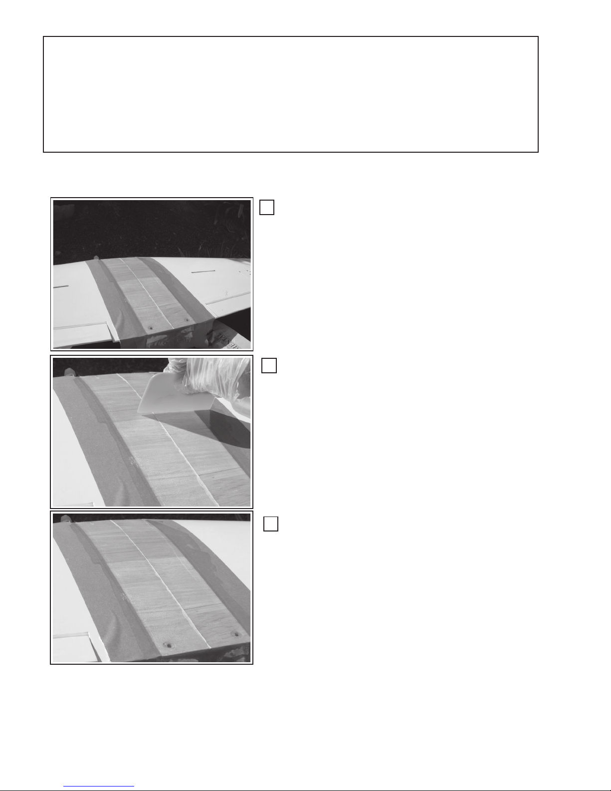
Optional Assembly Procedures:
The following are optional assembly steps/processes that are referred to throughout the assembly manual. Whether or not one performs these steps is completely up to
the builder and how the builder might feel these procedures will enhance the strength or
performance of the airplane.
OAP-1: “WPFG-1” Wing Panel, Fiberglassing:
Prepare to Fiberglass:
After removal of the OraCover© material from the wing
bottom, as described in step 4, apply two strips of masking
tape at least 3/16” inside of the OraCover edge. Wrap the
masking tape around the leading and trailing edges. Apply
masking tape along the trailing edge at the intersection of the
trailing edge and the wing bottom. Repeat for the leading edge.
Cut a piece of fiberglass (1/2 to 2 oz.) to fit about 3/16” to
1/4” inside the masking and from the leading to trailing edge.
Apply Fiber glass:
Mix fiberglass resin (polyester or thinned-epoxy), apply
to the fiberglass cloth and squeegee out as shown. Squeegee
it thoroughly into the fiberglass cloth and do not let it built up
too much. Allow to flow and drip off the leading and trailing
edges .... the masking tape will prevent the resin from flowing
under the wing. Allow to cure.
Finish:
Remove the tape and trim (flush) any cured fiberglass
from the leading and trailing edges. Sand as necessary.
Return to steps 4 and 5
34
Page 35
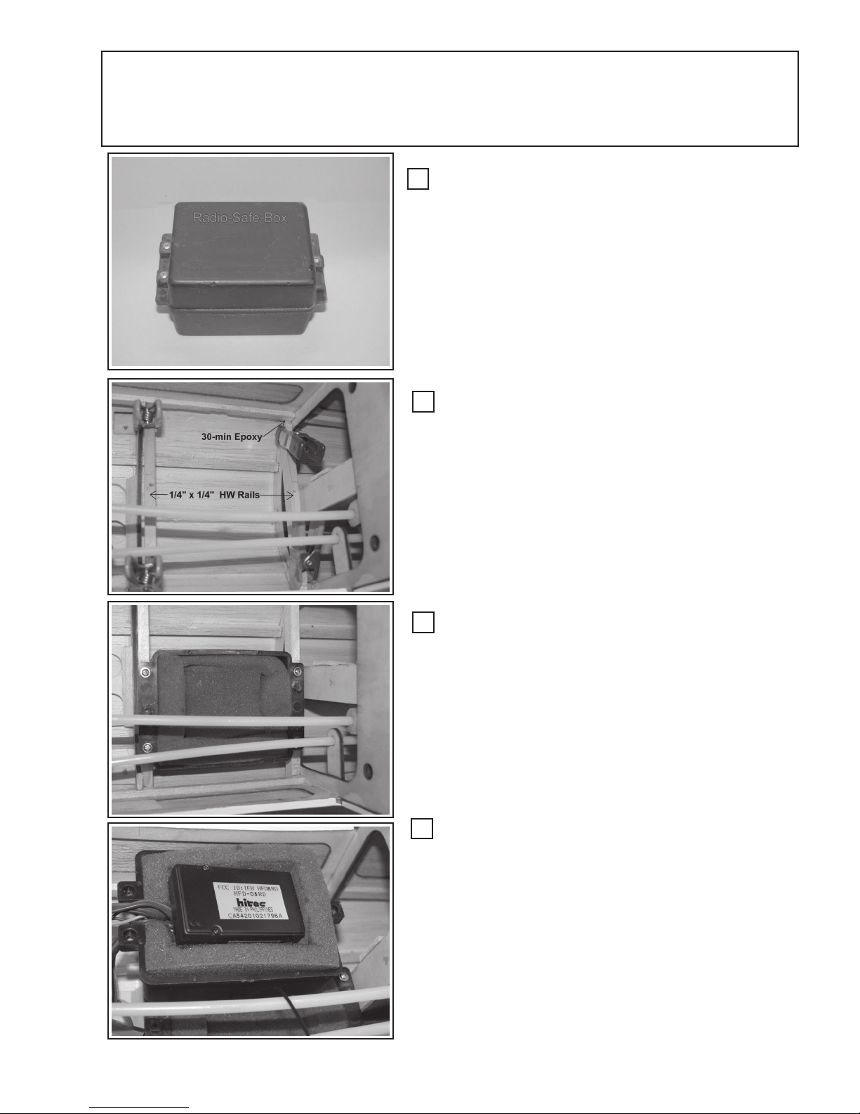
“Receiver Safe-Box” Installation (Optional)
Radio-Safe-Box®:
It may be elected to install a “Radio-Safe-Box” to protect
the receiver and possible the battery from damage during
crashes or other mishaps.
The “Radio-Safe-Box” is available from Golden Skies R/
C Aircraft, Inc. website, http://www.goldenskiesrc.com.
The Receiver-Safe-Box has saved many expensive
receivers and batteries from crash damage in the past.
Install Box Support Rails:
Cut two hardwood rails (1/4” x 5/16”) to the width of the
fuselage at F3 and F4 respectively. Epoxy the rails to the
formers and under the 1/4” fuselage stringer. (Shown left)
Attach Receiver Box:
Screw the box bottom to the rails after the epoxy has
cured using the four (4) screws provided with the Safe-Box.
Cut the interior foam to accept either the receiver alone,
or the receiver and battery together, depending upon the pitch
balancing requirements to move the battery fore or aft.
Install Receiver:
Plug the servos into the receiver and place receiver into
the cut out foam. Dress servo wire out the opening provided
and the antenna out the top lid hole. Place the Safe-lid on
top of the bottom box and screw in place using the screws
provided. Mark the box with the:
- Receiver model # and Channel Number
- Battery Voltage and mAh capacity.
- Indicate Servo Pin polarity orientation for reference.
35
Page 36
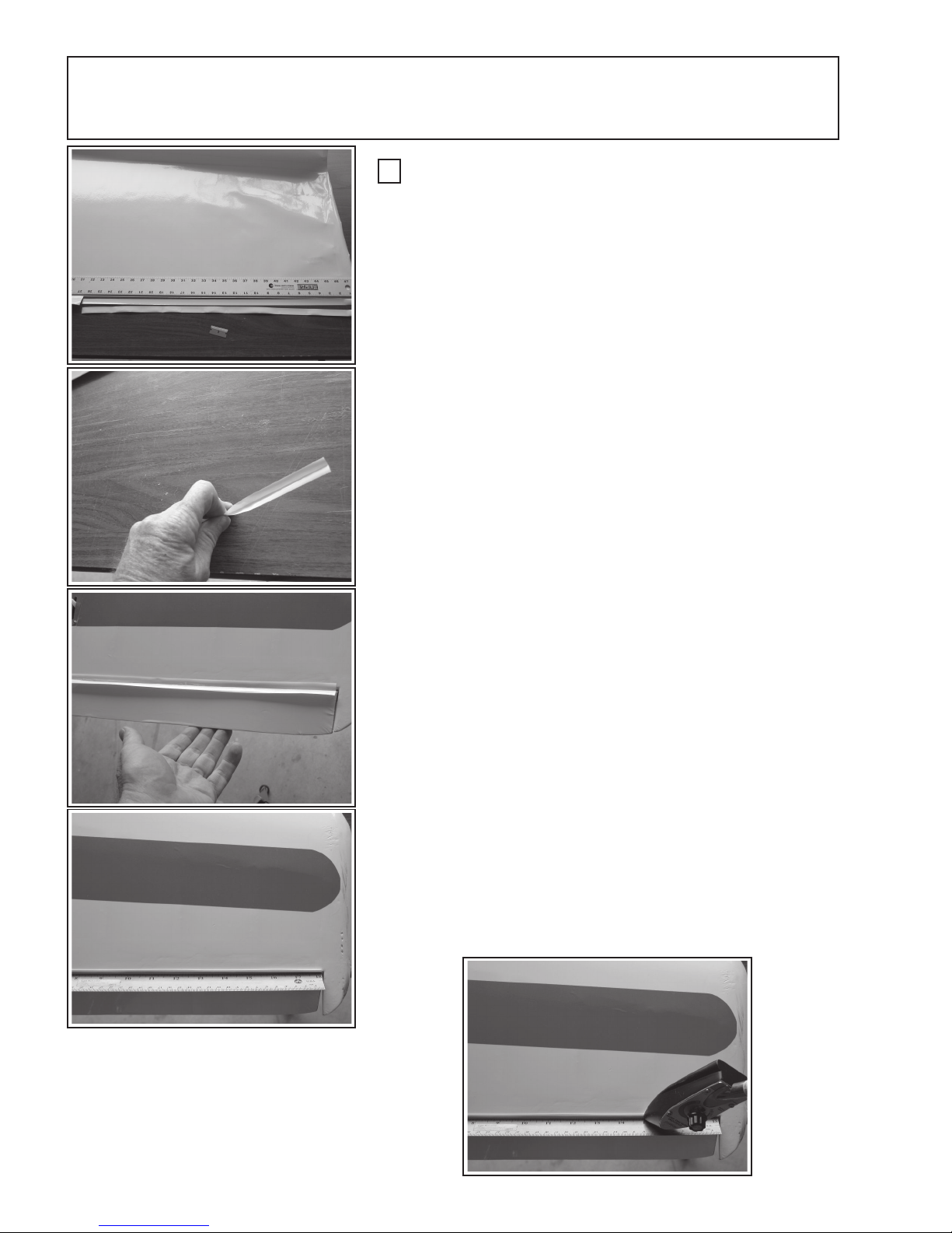
Seal Control Hinge Gaps:
Cut OraCover Seals:
Cut the following strip of OraCover to seal the listed control
surfaces:
o Ailerons 26” x 5/8” 2 ea White
o Elevators 9” x 5/8” 2 ea White
o Rudder 9-3/4” x 5/8” 1 ea White
Fold each strip in the middle along its length with the OraCover’s
outer surface (shinny) to the inside of the fold. This is to allow the
adhesive surface to adhere to the hinge joint area
Place the sealing strip in the hinge joint as shown left. Place
the strip on the under side of the surface. That is the underside of
the wing-ailerons and elevators and either side of the rudder. It
only necessary to seal one side, although you may seal both sides
if you wish.
Place a thin ruler in the seal-strip center to force the fold down
to the hinge line.
Using a sealing iron, tack and secure the entire length of the
seal strip to one surface. Lay the ruler to the opposite side and seal
the other side. Repeat for all control surfaces
36
Page 37

Balancing the CrossFire 320E (Pitch, Roll & Yaw)
It is critical that you balance the airplane correctly. An improperly balanced
plane, particularly in pitch, will be unstable, causing loss of control and crashing.
Pitch Balance:
The Center of Gravity (C/G) for pitch is located 10 - 1/8” back from the front
surface of the firewall. Decals have been provided to place on the fuselage side
and wing bottom at the C/G location for reference. This position represents the
25% of
pitch C/G is 25% to 30% of MAC. However, it is important that you set the C/G at
25% to start out your first test flights, as this makes the plane tend toward being
nose heavy. It is much safer to start slightly nose heavy on the initial flight and
adjust the pitch C/G thereafter.
from the firewall’s front surface. (This represents the 30% MAC point.)
Mean Aerodynamic Chord (MAC). The generally accepted range for the
It is not recommended that the C/G be located any further back than 11” back
Balance the Pitch with the fuel tank empty, but with all other aspects of the
plane prepared to fly.
Turn the plane upside-down and place your fingers under the wing at the C/G point (the location on
the wing is virtually at the intersection of the leading edge and the tip rib). However, it is easier if you
mark the C/G on each wing panel wing, using the C/G decals provided, about 5 - 6 inches out from the
root or wing center. Place you fingers on the C/G points you just marked and carefully lift the plane up.
If the nose falls, the plane is too nose heave. If the tail falls, it is too tail heavy.
To correct, adjust the battery mounting location fore or aft as needed to set the balance as level as
possible. If you can not achieve pitch balance by relocating the battery, then you must add weight to
either the tail or nose to compensate.
Do not attempt to fly the plane outside the above pitch balance range or
uncontrolled flight and/or a crash will result.
Once you have flown and familiarized yourself with the CrossFire’s flight characteristics, you may
move the pitch C/G within the range above to suit your flying style. Moving the C/G backwards will make
the CrossFire more pitch responsive and less stable. Moving the pitch C/G forward will make the CrossFire
more stable, more likely to “self recover” from a stall, but less responsive.
37
Page 38

Lateral (Roll) Balance:
Roll is controlled by the aircraft ailerons and if not balanced, the left and right aileron response will not be
uniform or equal. Also, during loops and other aerobatics, one of the wings is likely to droop and cause an adverse
and undesired flight path.
In this procedure you will balance along the lateral or roll axis. This axis is a line extending from the tip of the
spinner straight back along the thrust line to the planes’ tail. This balance will keep the wing more level during
maneuvers, and is mandatory for good aerobatic performance.
With the plane upside down, tie a string to the propeller shaft and another to the tail area along the thrust line.
With the assistance of another, lift the plane using the strings and observe which, if any, of the wings panels drops.
Add weight to the opposite wing at the wing tip by drilling a small hole and adding weight, secured with epoxy. Add
and/or remove weight to achieve perfect lateral balance. Cover the hole with a small piece of OraCover©.
Yaw Balancing:
Aircraft yaw is controlled by the aircraft’s rudder. This axis is not as important as Pitch and Roll; however,
if you have adjusted the pitch balance correctly, the yaw should be set adequately.
Control Throws:
The control throw is the amount, any one of the control surfaces, can move and is
generally measured in inches above or below the neutral position or in degrees of deflection relative to the neutral position.
GSRC will give three ranges: 1) for intermediate sport-pilots; 2) for intermediate to
advance aerobatic pilots; and 3) for advanced, 3-D or freestyle pilots.
We will address adjusting the control throws using mechanical adjustments in the
servo control arms, push-rods and length of the control surface horns.
There are two ways to adjust the control throws:
1. Mechanical: Using the servo arms, push-rods and control horns
2. Transmitter adjustments: Using computer-controls and multilevel rates or rate switches. Adjust ments in this manor are beyond the scope of this assembly manual and we refer you to your
transmitter manual for assistance.
For Intermediate Sport Pilots:
Up Down Deflection (deg)
Elevators: 3/8 - 1/2 inches 3/8 - 1/2 inches ~ 10 deg
Ailerons: 3/8 - 1/2 inches 3/8 - 1/2 inches 10 - 15 deg
Rudder: 1-1/2 - 1-3/4 inches left and right
For Intermediate to Advance Aerobatic Pilots:
Elevators: 3/4 - 1 inches 3/4 - 1 inches ~ 16 deg
Ailerons: 3/4 - 1 inches 3/4 - 1 inches 21 - 30 deg
Rudder: 1-3/4- 2 inches left and right
Up Down Deflection (deg)
38
Page 39

For Advance 3-D and FreeStyle Pilots:
Up Down Deflection (deg)
Elevators: 1.5 - *** inches 1.5 - *** inches 30-40 deg ***
Ailerons: 1 - 1.25 inches 1 - 1.25 inches
Rudder: Maximum, to the point just short of touching the elevators
(***) as much as you want and can safely handle.
To mechanically adjust the throws:
Increase Throws:
1. Move the push-rod further out on the servo control arm
a. Use a longer servo control arm (take care not to stall the servo)
and/or
2. Move the push-rod closer in or down on the control horn.
Decrease Throws:
1. Move the push-rod further in, toward the pivot point on the servo control arm
and/or
2. Move the push-rod further out or up on the control horn.
a. Use a longer control horn as needed.
The more elevator control throw you have above the “Intermediate Pilot” recommendations will cause the
airplane to snap roll when:
1. Abrupt up or down elevator movements are made, .... and/or
2. At the top of loops.
Be aware of possible abrupt and undesired flight behaviors as one increases the amount of elevator throw.
Only very experienced pilots should set the throws above the “Sport Pilot” recommended throws. Also be
aware that overall weight, power applied and C/G pitch location will each, and all, effect the ‘unintended’ snap
roll behavior.
Preflight and Safety Checks:
Do these checks prior to going to the flying field and again at the field
1. Charge your transmitter and receiver batteries, using the manufacturer’s recommendation the night
before you fly. As a general rule, charge the batteries at the batteries’ milli-Ampere-hour rating (ex: 600 mAh)
divided by ten (10) for 12-15 hours. (ex: 600 mAh / 10 = 60 mAh charge rate)
2. With a experienced builder/pilot, check every mechanical connection:
a. Servo, servo-arms, push-rods, clevises, control horns.
b. All Screws and bolts and blind nuts
c. Glue joints
d. Control Surface Hinges
e. Landing Gear, wheels and collars and attachment hardware.
f. Spinner
g. Fuel tank security and plumbing
39
Page 40

3. With a experienced builder/pilot, check every electrical connection:
a. Battery and Receiver mounting to fuselage
b. Battery to switch connection
c. Switch to receiver connection
d. Receiver to Servo connections (Elevator, Rudder, Ailerons, Throttle)
4. Recheck the balance: ( Check with the fuel tank empty)
5. Check the movement of the control surfaces: (Obey your club rules, be sure you have a “
FREQUENCY before turning on your transmitter.
a. Check the control surfaces for unimpeded and nonbinding movement.
b. Check that the control surface moves in the correct and corresponding direction relative to
the transmitter control stick movement.
c. Set a mechanical or electrical trims, sub-trims, centering to the neutral position.
d. Check the location of the antenna and that it is secure and has a “strain-relief” on it.
6. If your transmitter has “Dual-Rates”, set the dual-rate switch for low rates.
a. Check to see that the control surface move the intended amounts in each of the “rate” posi tions.
7. Properly balance the propeller. An out of balance propeller is dangerous to you and to others and will
cause structurally damaging vibration to your plane and eventual failure.
8. Range test the radio. With the transmitter antenna in the down or collapsed position, the receiver/
battery switch on, move the controls to affirm smooth, non-jittering control of the control surfaces.
Walk away from the airplane to a distance of about 100-125 feet. While walking away, affirm
that you have complete, smooth and non-jittering control of the control surfaces.
If not, do not
CLEAR”
attempt to fly.
Possible Failure Causes:
- Loose Servo connections
- Low Battery charge (Tx or Rx)
- Corrosion
- Intermittent or faulty switch
- Damaged or improperly routed Receiver antenna
- Bad or cracked Rx crystal, (if you are using a receiver that has been in a prior crash)
- Loose or vibrating bolts or engine.
Repeat this test with the engine running. Be sure someone is firmly securing
the airplane while the engine is running. NEVER leave a running airplane engine unattended and/or unsecured.
Although this test gives one a ‘degree of comfort’, it is NOT a definitive test of
your radio and control system. Passing this test does not assure proper inflight radio function.
9. Propeller & spinner secure - propeller properly balanced & undamaged - Do not use a
damaged propeller.
9. Follow all AMA rules and regulations and those of your local flying club.
40
Page 41

Radio Controls:
The transmitter controls setup are totally dependant upon the radio system you are using and the MODE
you are flying. In the USA, the MODE is generally “mode - 2”. Mode two (2) and will assumed. A briefly
description of the transmitter control functions and how they relate to the airplane control surfaces follows. For
a complete discussion of the transmitter control functions, please consult, read, and thoroughly understand the
manufacturer’s manual that came with your transmitter.
The two transmitter control “sticks” (left and right sticks; hereafter referred to as “LS” and “RS”)
control the flight surface functions as follows:
Left Stick (LS): Controls the Rudder (left-right) and Throttle (up-down)
Right Stick (RS): Controls the Ailerons (left-right) and elevator (up-down)
(*) The “Transmitter - Stick” movements (below) are assuming that only one stick is moved and in one
direction only at a time. The aircraft response to movement to one or more sticks simultaneously is beyond the
intended scope of this assembly manual. Consult your transmitter manual or a flight instruction book.
Roll Control (Ailerons):
Stick Position Control Surface Response Plane Response *
RS to Right Right aileron up Plane rolls to right (1)
Left aileron down
RS to Left Left aileron up Plane rolls to left (1)
Right aileron down
Pitch (Up - Down) Control (Elevator):
Stick Position Control Surface Response Plane Response *
RS to lower (down) Elevator moves upward Plane Climbs
RS to top (up) Elevator moves downward Plane Descends (Dives)
Yaw Control (left-right) (Rudder):
Stick Position Control Surface Response Plane Response *
LS to Right Rudder moves to right Plane “Flat” turns to right (1)
LS to Left Rudder moves to left Plane “Flat” turns to left (1)
Throttle Control (Engine Speed):
Stick Position Control Surface Response Plane Response *
LS to top (up) Engine speeds up Plane accelerates
LS to Bottom (down) Engine goes to idle Plane slows down, descends
(1) Most all control surfaces have some control cross-coupling. The rudder will cause some induced
rolling function and the ailerons will induce some yaw function.
41
Page 42

At the Field, First and Subsequent Flights:
Perform the Pre-Flight checks and tests as described in the Pre-Flight Section. One should get in the
habit of doing these checks before each flight.
Flying the CrossFire 320E
Take Off:
The CrossFire will taxi and track straight forward, if one has set up the rudder and nose wheel properly.
Smoothly run up the engine and allow speed to gather. Use most of the runway on your first flight. Gently, pull
back on the elevator stick and climb smoothly and gradually to a safe altitude. Do not “yank” the plane off the
ground on its first flights.
Flying:
Take it easy on the first flight and for several flights thereafter. Get a feel for the planes flying characteristics and trim for level flight with-the-wind (down wind). You may experience a bit of altitude gain into the wind
(up wind leg). This is normal. If this is a new engine, get several flights on it before stressing and testing it with
aggressive aerobatic maneuvers.
You may want to “pull-back” on the throttle to about half speed to allow for greater reaction time until you
get accustomed to the flight characteristics.
The CrossFire is a smooth, yet responsive aircraft. Try a few loops and axial rolls to test its aerobatic
performance. Move to a safe altitude and throttle back to a near idle to check its slow speed handling in
preparation for landing. The CrossFire will not slow down immediately when you throttled back due to its very
sleek fuselage profile. So be prepared to bleed off some speed well before the landing approach.
With the sleek profile, the CrossFire will glide very well and one should not over react to a “dead-stick”
situation. Don’t over control, let the CrossFire glide back to the field.
Landing:
The CrossFire can land smooth and slow, or, hot and fast. Remember to bleed off some speed for a slow
and smooth landing. It has excellent slow speed characteristics, and forgiving and straight forward stall behaviors. Fly your normal pattern, but throttle back a little sooner than normal to bleed off speed.
Line up on the runway and allow the plane to descend normally. With the tricycle gear, you can three
point or rear wheel landing (on the wing wheels) the plane. With a low wing, the plane will tend to “sit-down” on
the runway quickly and roll out smoothly.
Stop the engine well short of the pit (follow your clubs rules ...... never taxi or return your plane with the
engine running to the pit area). Return your plane to the pit and perform the “Pre-Flight” tests. Check again to
be sure nothing has come loose.
42
Page 43
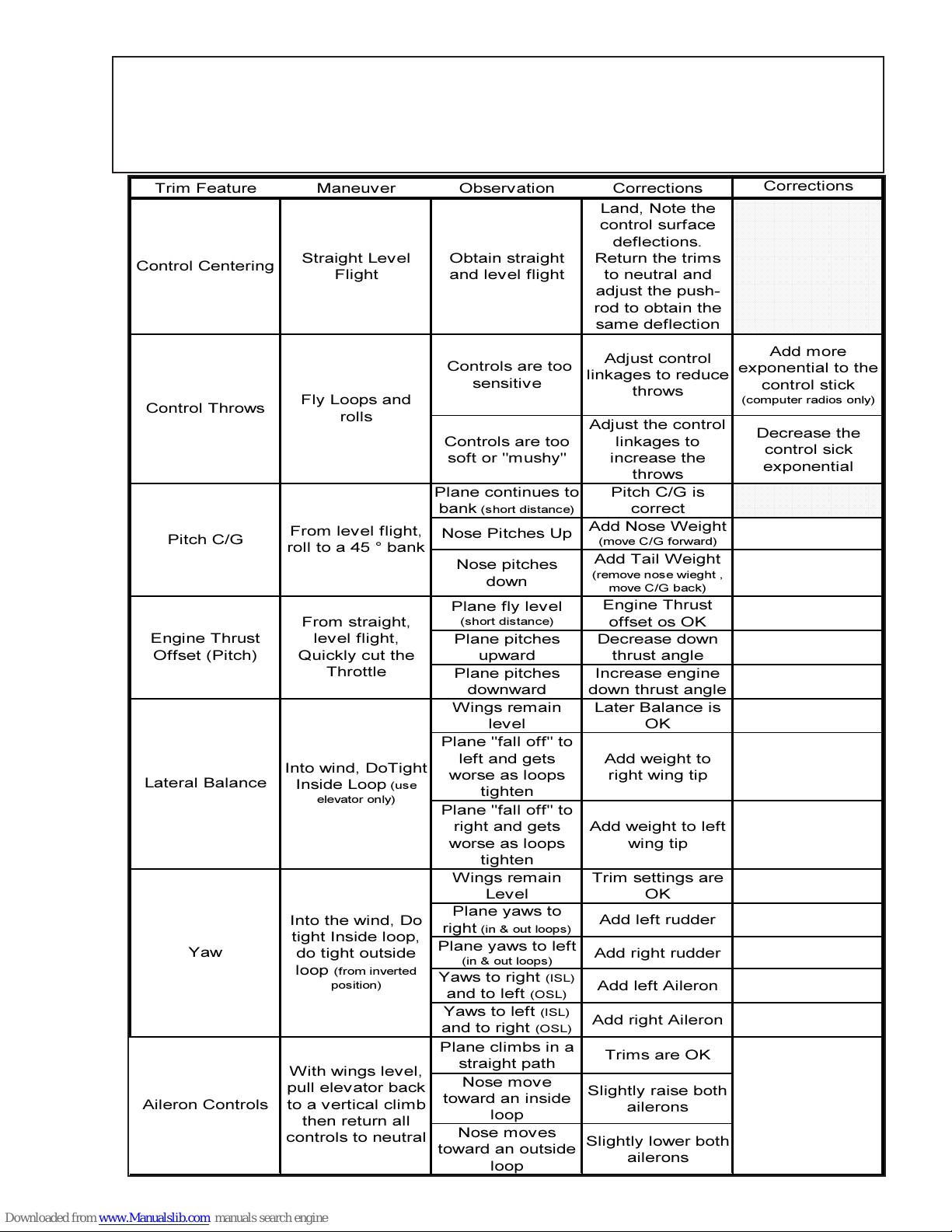
Flight Trimming and Performance Evaluation
000000000000000000000000000000000000000000000000000000000000000000000000000000000000000000000000000000
0
0000
0
0000
0
0000
0
0000
0
0000
0
0000
0
0000
0
0000
0
0000
0
0000
0
0000
0
0000
0
0000
0
0000
000000000000000000000000000000000000000000000000000000000000000000000000000000000000000000000000000000
000000000000000000000000000000000000000000000000000000000000000000000000000000000000000000000000000000
0
0000
0
0000
0
0000
000000000000000000000000000000000000000000000000000000000000000000000000000000000000000000000000000000
Chart
Trim Feature Maneuver Observation Corrections
Land, Note the
control surface
deflections.
Control Centering
Straight Level
Flight
Obtain straight
and level flight
Return the trims
to neutral and
adjust the pushrod to obtain the
same deflection
Adjust control
linkages to reduce
throws
Adjust the control
linkages to
increase the
Control Throws
Controls are too
sensitive
Fly Loops and
rolls
Controls are too
soft or "mushy"
throws
Pitch C/G is
correct
Add Nose Weight
(move C/G forward)
Add Tail W eight
(remove nose wieght ,
move C/G back)
Engine Thrust
offset os OK
Decrease down
thrust angle
Increase engine
down thrust angle
Later Balance is
OK
Pitch C/G
Engine Thrust
Offset (Pitch)
From lev el flight,
roll to a 45 ° bank
From straight,
level flight,
Quickly cut the
Throttle
Plane continues to
(short distance)
bank
Nose Pitches Up
Nose pitches
down
Plane fly level
(short distance)
Plane pitches
upward
Plane pitches
downward
Wings remain
level
Corrections
0000000000000000000000000000000000000000000000000000000000000000000000000000000000000000000000000
0000000000000000000000000000000000000000000000000000000000000000000000000000000000000000000000000
0000000000000000000000000000000000000000000000000000000000000000000000000000000000000000000000000
0000000000000000000000000000000000000000000000000000000000000000000000000000000000000000000000000
0000000000000000000000000000000000000000000000000000000000000000000000000000000000000000000000000
0000000000000000000000000000000000000000000000000000000000000000000000000000000000000000000000000
0000000000000000000000000000000000000000000000000000000000000000000000000000000000000000000000000
0000000000000000000000000000000000000000000000000000000000000000000000000000000000000000000000000
0000000000000000000000000000000000000000000000000000000000000000000000000000000000000000000000000
0000000000000000000000000000000000000000000000000000000000000000000000000000000000000000000000000
0000000000000000000000000000000000000000000000000000000000000000000000000000000000000000000000000
0000000000000000000000000000000000000000000000000000000000000000000000000000000000000000000000000
0000000000000000000000000000000000000000000000000000000000000000000000000000000000000000000000000
0000000000000000000000000000000000000000000000000000000000000000000000000000000000000000000000000
Add more
exponential to the
control stick
(com puter radios only)
Decrease the
control sick
exponential
0000000000000000000000000000000000000000000000000000000000000000000000000000000000000000000000000
0000000000000000000000000000000000000000000000000000000000000000000000000000000000000000000000000
0000000000000000000000000000000000000000000000000000000000000000000000000000000000000000000000000
Plane "fall off" to
Lateral Balance
Into wind, DoTight
Inside Loop
elevator only)
(use
left and gets
worse as loops
tighten
Plane "fall off" to
right and gets
worse as loops
Add weight to
right wing tip
Add weight to left
wing tip
tighten
Wings remain
Level
Plane yaws to
(in & out loops)
right
Plane yaws to left
(in & out loops)
Yaws to right
and to left
Yaws to left
and to right
(OSL)
(ISL)
(OSL)
Yaw
Into the wind, Do
tight Inside loop,
do tight outside
(from inverted
loop
position)
Plane climbs in a
Aileron Controls
pull elev ator back
to a vertical climb
then return all
controls to neutral
With wings level,
straight path
Nose move
toward an inside
loop
Nose moves
toward an outside
loop
43
Trim settings are
Add left rudder
Add right rudder
(ISL)
Add left Aileron
Add right Aileron
Trims are OK
Slightly raise both
ailerons
Slightly lower both
ailerons
OK
Page 44
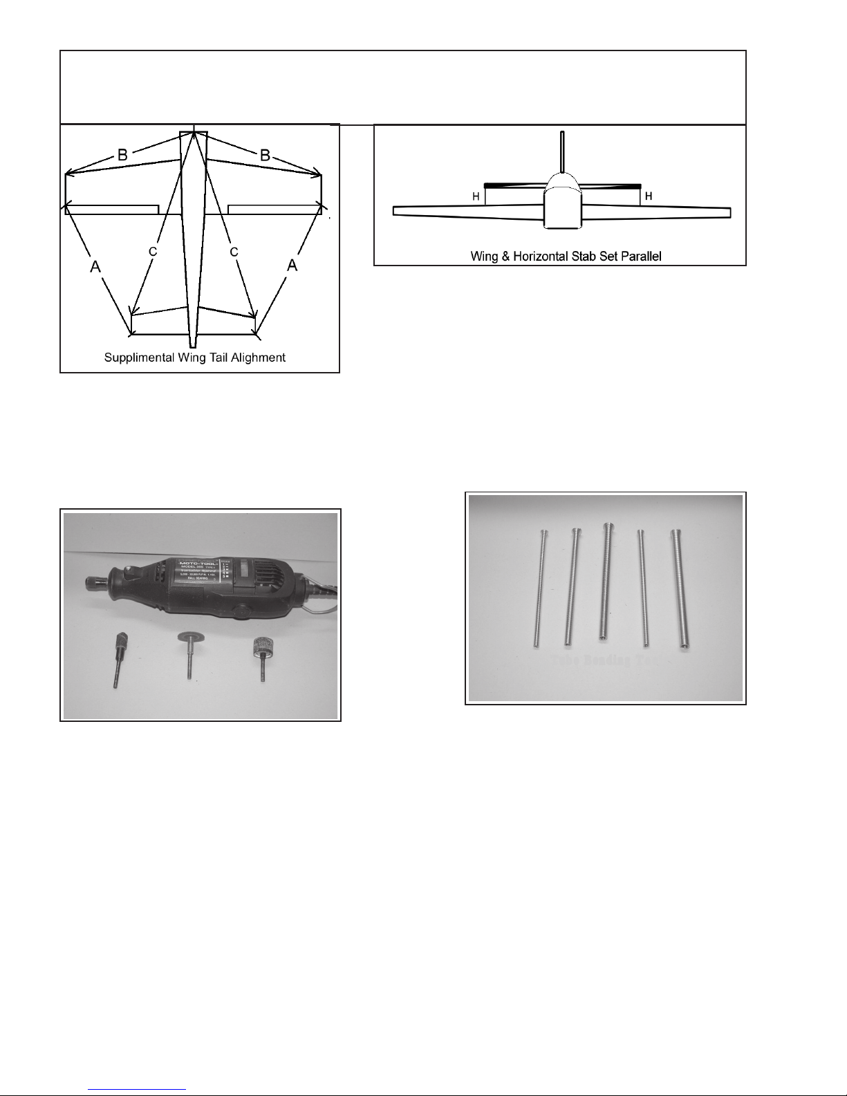
Supplemental Pictures and Figures
Figure 2:
Wing and Tail Alignment
with respect to
Fuselage
Figure 3:
Wing Leveling Diagram
Figure 4:
Dremel Tool with
sanding drums and cutting
disc.
Figure 5:
Tube Bending Tools
44
Page 45
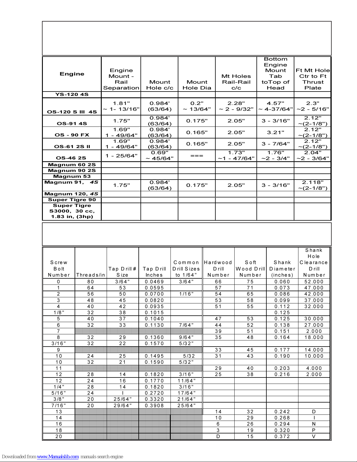
0000000000000000000000000000000000000000000000000000000000000000000000000000000000000000000000000000000000000000000000000000000000000000000000000000000000000000000000000000000000000000000000000000000000000000000000000000000000000
0000000000000000000000000000000000000000000000000000000000000000000000000000000000000000000000000000000000000000000000000000000000000000000000000000000000000000000000000000000000000000000000000000000000000000000000000000000000000
0000000000000000000000000000000000000000000000000000000000000000000000000000000000000000000000000000000000000000000000000000000000000000000000000000000000000000000000000000000000000000000000000000000000000000000000000000000000000
0000
0000000000000000000000000000000000000000000000000000000000000000000000000000000000000000000000000000000000000000000000000000000000000000000000000000000000000000000000000000000000000000000000000000000000000000000000000000000000000
0000000000000000000000000000000000000000000000000000000000000000000000000000000000000000000000000000000000000000000000000000000000000000000000000000000000000000000000000000000000000000000000000000000000000000000000000000000000000
0000
0000000000000000000000000000000000000000000000000000000000000000000000000000000000000000000000000000000000000000000000000000000000000000000000000000000000000000000000000000000000000000000000000000000000000000000000000000000000000
0000
0000
0000
0000
0000
0000
0000
0000
0000
0000000000000000000000000000000000000000000000000000000000000000000000000000000000000000000000000000000000000000000000000000000000000000000000000000000000000000000000000000000000000000000000000000000000000000000000000000000000000
Engine
YS-120 4S
OS-120 S III 4S
OS-91 4S
OS - 90 FX
OS-61 2S II
OS-46 2S
Magnum 60 2S
Magnum 90 2S
Magnum 53
Magnum 91, 4S
Magnum 120, 4S
Super Tigre 90
Super Tigre
S3000, 30 cc,
1.83 in, (3hp)
Table 2:
Engine Mount Rail Separation for Various Engines
Engine
Mount -
Rail
Separation
1.81"
~ 1- 13/16"
1.75"
1.69"
1 - 49/64"
1.69"
1 - 49/64"
1 - 25/64"
1.75"
Mount
Hole c/c
0.984'
(63/64)
0.984'
(63/64)
0.984'
(63/64)
0.984'
(63/64)
0.69"
~ 45/64"
0.984'
(63/64)
Mount
Hole Dia
0.2"
~ 13/64"
0.175" 2.05" 3 - 3/16"
0.165" 2.05" 3.21"
0.165" 2.05" 3 - 7/64"
===
0.175" 2.05" 3 - 3/16"
Mt Holes
Rail-Rail
c/c
2.28"
~ 2 - 9/32"
1.73"
~1 - 47/64"
Bottom
Engine
Mount
Tab
toTop of
Head
4.57"
~ 4-37/64"
1.76"
~2 - 3/4"
Ft Mt Hole
Ctr to Ft
Thrust
Plate
2.3"
~2 - 5/16"
2.12"
~(2-1/8")
2.12"
~(2-1/8")
2.12"
~(2-1/8")
2.04"
~2 - 3/64"
2.118"
~(2-1/8")
Table3: Typical Screw-Bolt Sizes and Drill-Taps Sizes
Shank
Hole
Screw
Bolt
Number Threads/in
Tap Drill #
Size
Ta p D rill
In c he s
0 80 3/64" 0.0469 3/64" 66 75 0.060 52.000
1 64 53 0.0595 57 71 0.073 47.000
2 56 50 0.0700 1/16" 54 65 0.086 42.000
3 48 45 0.0820 53 58 0.099 37.000
4 40 42 0.0935 51 55 0.112 32.000
1/8" 32 38 0.1015 0.125
5 40 37 0.1040 47 53 0.125 30.000
6 32 33 0.1130 7/64" 44 52 0.138 27.000
7 39 51 0.151 2.000
8 32 29 0.1360 9/64" 35 48 0.164 18.000
3/16" 32 22 0.1570 5/32"
000000000000000000000000000000000000000000000000000000000000000000000000000000000000000000000000000000000000000000000000000000000000000000000000000000000000000000000000000000000000000000000000000000000000000000000000000000000
9 33 45 0.177 14.000
10 24 25 0.1495 5/32 31 43 0.190 10.000
10 32 21 0.1590 5/32"
11 29 40 0.203 4.000
000000000000000000000000000000000000000000000000000000000000000000000000000000000000000000000000000000000000000000000000000000000000000000000000000000000000000000000000000000000000000000000000000000000000000000000000000000000
12 28 14 0.1820 3/16" 25 38 0.216 2.000
12 24 16 0.1770 11/64"
1/4" 28 14 0.1820 3/16"
5/16" 24 I 0.2720 17/64"
3/8" 20 25/64" 0.3320 21/64"
7/16" 20 29/64" 0.3908 25/64"
13 14 32 0.242 D
14 10 29 0.268 I
16 6 26 0.294 N
18 3 19 0.320 P
20 D 15 0.372 V
000000000000000000000000000000000000000000000000000000000000000000000000000000000000000000000000000000000000000000000000000000000000000000000000000000000000000000000000000000000000000000000000000000000000000000000000000000000
000000000000000000000000000000000000000000000000000000000000000000000000000000000000000000000000000000000000000000000000000000000000000000000000000000000000000000000000000000000000000000000000000000000000000000000000000000000
000000000000000000000000000000000000000000000000000000000000000000000000000000000000000000000000000000000000000000000000000000000000000000000000000000000000000000000000000000000000000000000000000000000000000000000000000000000
000000000000000000000000000000000000000000000000000000000000000000000000000000000000000000000000000000000000000000000000000000000000000000000000000000000000000000000000000000000000000000000000000000000000000000000000000000000
000000000000000000000000000000000000000000000000000000000000000000000000000000000000000000000000000000000000000000000000000000000000000000000000000000000000000000000000000000000000000000000000000000000000000000000000000000000
000000000000000000000000000000000000000000000000000000000000000000000000000000000000000000000000000000000000000000000000000000000000000000000000000000000000000000000000000000000000000000000000000000000000000000000000000000000
000000000000000000000000000000000000000000000000000000000000000000000000000000000000000000000000000000000000000000000000000000000000000000000000000000000000000000000000000000000000000000000000000000000000000000000000000000000
000000000000000000000000000000000000000000000000000000000000000000000000000000000000000000000000000000000000000000000000000000000000000000000000000000000000000000000000000000000000000000000000000000000000000000000000000000000
000000000000000000000000000000000000000000000000000000000000000000000000000000000000000000000000000000000000000000000000000000000000000000000000000000000000000000000000000000000000000000000000000000000000000000000000000000000
Common
D ri ll S ize s
to 1/64"
45
Hardwood
D rill
Number
Soft
Wood D rill
Number
Shank
Diameter
(inches)
Clearance
D rill
Number
Page 46
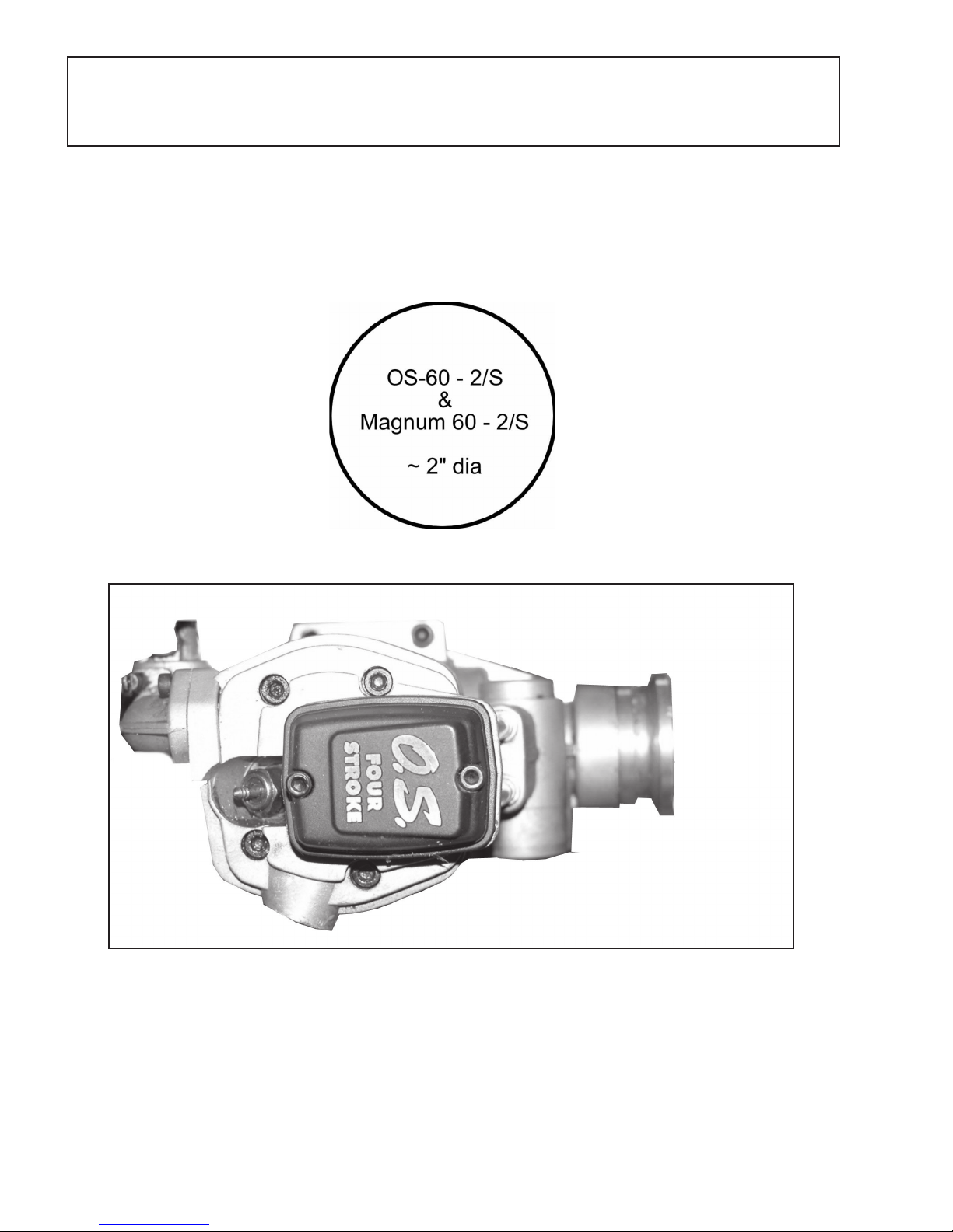
Engine Drawings
Please refer the Golden Skies Website to obtain downloadable drawings of various
engine profiles.
http://www.goldenskiesrc.com
OS-91 4/S Outlie
46
Page 47

Product Evaluation Request:
Golden Skies R/C Aircraft, Inc. is dedicated to the highest quality products and superior customer
service. GSRC seeks and values our customer’s feed back. It is our customer’s thoughts and ideas that
assist GSRC to achieve continued product and customer service improvements. Help us define what you
want in a ARF kit, manual and customer service.
Please mark all answers your feel are correct or meaningful.
1. What does ARF quality mean to you?
a) Lots of features b) Superior After-Market Hardware c) Ease of assembly d) detailed
manuals w/ many pictures e) OraCover covering f) Properly fitting Parts g) Repairability
h) Symmetrical, airfoil tail surfaces i) other ____________________________________________
2. What is our Quality worth relative to typical ARF Base Cost? (Say a 60-size ARF typically costs $250.00)
a) + $5.00 b) + $10.00 c) + $20.00 d) +$30.00 e)+ $35.00 f) other _______
3. What is the extra value of the After-Market Hardware included in the CrossFire ARF?
a) $0 b) + $10.00 c) + $15.00 d) + $ 20.00 e) + $25.00 f) + $30.00 g) + $35.00
4. Was the CrossFire 320E assembly easy? (Scale of 1 - 10, 1 = easy, 10 = difficult)
Rating: __________, Explain: __________________________________________________________
5. Was the manual clear, easy to follow and in a logical assembly order? (Scale 1 - 10, same as above)
Rating: _________, Explain: _________________________________________________________
6. Were there any damaged or missing parts? (Yes / No)
If yes, please explain: ________________________________________________________________
7. How is the extra strength designed and manufactured into the CrossFire important to you?
a) Firewall 35 pound static pull strength, Rating (1-10) ______ (1 = not important, 10 = most important)
b) Extra Spar over wing landing gear, Rating (1-10) ______ (1 = not important, 10 = most important)
c) Lite-Ply ribs in the wing gear area, Rating (1-10) ______ (1 = not important, 10 = most important)
d) 3/16” wire landing gear, Rating (1-10) ______ (1 = not important, 10 = most important)
e) Steel Control Horns, Rating (1-10) ______ (1 = not important, 10 = most important)
f) Steel Pull-pull rudder system, Rating (1-10) ______ (1 = not important, 10 = most important)
g) Rigid fuel tank walls, Rating (1-10) ______ (1 = not important, 10 = most important)
h) “4-40” push-rod material, Rating (1-10) ______ (1 = not important, 10 = most important)
i) Steel Clevises w/retainer springs and locknuts, Rating (1-10) ______ (1 = not important, 10 = most important)
j) Solid lite-Ply wing-servo mounts, Rating (1-10) ______ (1 = not important, 10 = most important)
k) OraCover, re-shrinkable Covering, Rating (1-10) ______ (1 = not important, 10 = most important)
l) 1/4” x 24 nylon wing bolts, Rating (1-10) ______ (1 = not important, 10 = most important)
m) Adjustable Engine mount, Rating (1-10) ______ (1 = not important, 10 = most important)
n) Fiberglass Cowl, Rating (1-10) ______ (1 = not important, 10 = most important)
8. How are easy-build features included the CrossFire important to you?
a) Precut and installed Canopy, Rating (1-10) ______ (1 = not important, 10 = most important)
b) Colored, precut and predrilled Cowl, Rating (1-10) ______ (1 = not important, 10 = most important)
c) Pre-installed Servo Tray, Rating (1-10) ______ (1 = not important, 10 = most important)
d) Pre-trimmed OraCover material, Rating (1-10) ______ (1 = not important, 10 = most important)
e) Precut and oriented wing-servo plates, Rating (1-10) ______ (1 = not important, 10 = most important)
9. Did we meet our goal of making the CrossFire superior to the typical ARF kit by ......?
a) +5% b) +10% c) +15% d) +20% e) +25% f) +30% g) other _______
10. Are you satisfied with the finished CrossFire 320E ARF? Yes / No, Explain:
____________________
_________________________________________________________________________________
47
Page 48
48
Page 49

Notes:
49
Page 50

This Page, intensionally left blank.
50
Page 51

Read and Accept Disclaimer,
Liability,
Indemnification, and
Assumption of Risk
Before
Purchasing the
Product
See Pages 5 - 7 for full text
The back page of this
Assembly Manual is an overview of the
Assumption of Risk Legal agreement only.
51
Page 52
Safety Warning and Disclaimer (Partial) and
Assumption of Risk
See Full Statement, Pages 5 - 7
Warning
The Radio Controlled (R/C), Almost Ready to Fly Aircraft (“ARF”) is NOT A TOY and is potentially dangerous
to property and individuals within several miles of your flying area. It is capable of causing death, serious
bodily harm, and property damage if it strikes an individual or personal property.
Assumption of the Risk
Participation in the operation of remote controlled aircraft is voluntary. I understand that the operation of
remote controlled aircraft is a dangerous sport which can result in bodily injury, death, and/or damage to
property for many reasons, including but not limited to airplane accidents involving third parties known and
unknown to the user; equipment failure, malfunction, or misuse; weather conditions such as storms and
lightning; the training, acts, omissions, recommendations or advice given by your local Hobby Shop or the
Academy of model Aeronautics concerning the operation of remote controlled aircraft and related activities
such as transportation to and from the site; and first-aid, emergency treatment or other services rendered
to me as a user or others. I understand and acknowledge that the above list of reasons is not complete or
exhaustive. I accept and hereby assume all risks of injury, death, illness or disease, or other damage to
myself, to others, or to my property which arise from participation in the referenced activities.
Release:
I hereby voluntarily release, and forever discharge GOLDEN SKIES R/C AIRCRAFT, INC., a California
Corporation, on its behalf and on the behalf of its successors and assigns, and each of them (“Golden
Skies”) and its subcontractors, and all other persons or entities associated with it, including other participants,
(hereafter collectively the released parties) from all liability, claims, demands, actions or causes of action
for bodily injury, death, illness, disease or damage to myself, to any participating minor child of mine, or to
my property which are related to, arise out of, or are in any way connected with participation in the above
referenced activities, including but not limited to those arising from any negligent or reckless acts or omissions
or breach of contract of the released parties, or hidden defects in the equipment used. This release is
intended to be as broad and inclusive as is permitted by California law, and shall be construed and interpreted
under California law. If any portion, clause or sub clause is held invalid, I agree that the balance shall
continue in full force and effect.
Maintain Proper Insurance Coverage:
It is also mandatory that all R/C airplane pilots obtain adequate insurance through their your homeowner’s
policy or a separate policy to cover liability in the event of property damage or injury to individuals or
personal property. Additionally, all R/C airplane pilots should join the AMA to become secondarily insured.
Indemnification:
The user of this product agrees to indemnify and defend Golden Skies R/C Aircraft, Inc., a California
Corporation, as well as all employees, shareholders, directors, officers and agents thereof ( “Golden Skies”)
, against any claims, lawsuits or actions arising as a result of the use of the radio controlled aircraft, and
shall pay for all legal expenses incurred by Golden Skies in connection with the defense of such matters,
whether or not such claims are resolved without trial or other final decision and whether or not such expenses
are incurred in the defense of litigation or simply incurred prior to litigation in connection with an informal
claim. The obligation of the user to indemnify Golden Skies is express and unequivocal. The user is expressly
obligated to indemnify Golden Skies for Golden Skies’ own negligence if any, which may give rise to any
claim arising in connection with the use or misuse of the aircraft or components thereof
52
 Loading...