

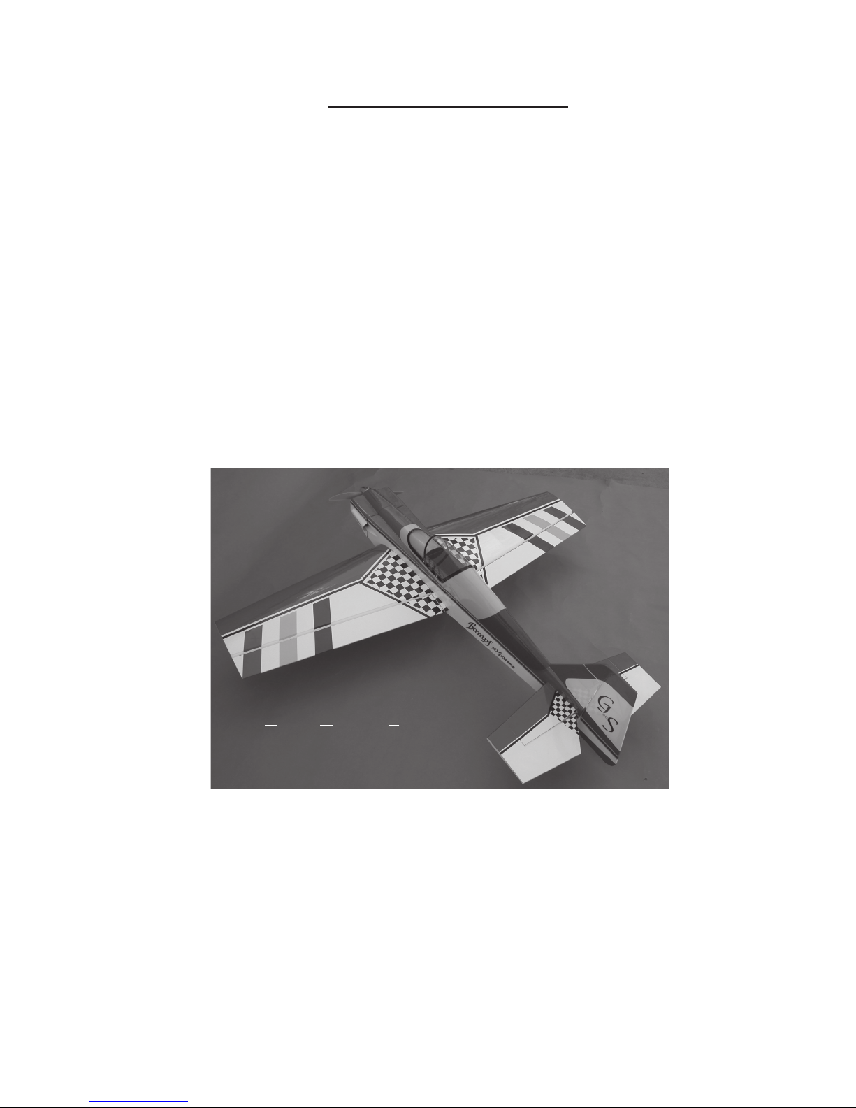
Golden Skies Bampf 3D Extreme Final Assembly Manual
BampfBampf
Bampf
BampfBampf
3D Extreme3D Extreme
3D Extreme
3D Extreme3D Extreme
Unlimited Sport Aerobatics and 3D Extremes
Final Assembly Manual
(Check www.goldenskiesrc.com for the most updated manuals)
Specifications:
Wing Span: 64 in, Area: 936 sq-in; Loading: 18.5 oz/sqft (@7.5 lbs)
Length: 60-1/2 in;
Weight: 7-1/2 to 8-1/2 pounds
Engine: 60 - 90 2/s or 90 4/s Sport Flying; 1.08 - 160 2/s or 120 to 140 4/s 3 D Flying
(Depending upon equip used)
90-1.08 2/S or 110 - 180 4/S
Almost Ready to Fly (ARF)
For Your Ultimate Enjoyment and Safety:
If this is your first ARF or RC model, Golden Skies R/C Aircraft, Inc. (GSRC) recommends that
you seek the knowledge and help of a long time, experienced modeler to assist you in the assembly
of this kit and to assist you in the preflight safety checks and first flights, during which you will be
trimming the plane for safety and performance. Your local hobby shop or the AMA association
(http:www.modelaircraft.org ) can assist you in finding a club, local expertise and a local flying
field. Seek a flying field with an AMA authorized club charter and one that has qualified flying
instructors. This is absolutely mandatory for your safety and the safety of others.
949-429-2910; http://www.goldenskiesrc.com Rev. 1.0 (2-16-06)
Golden Skies R/C Aircraft, Inc.
30882 Rivera Place, Laguna Niguel, CA 92677
1
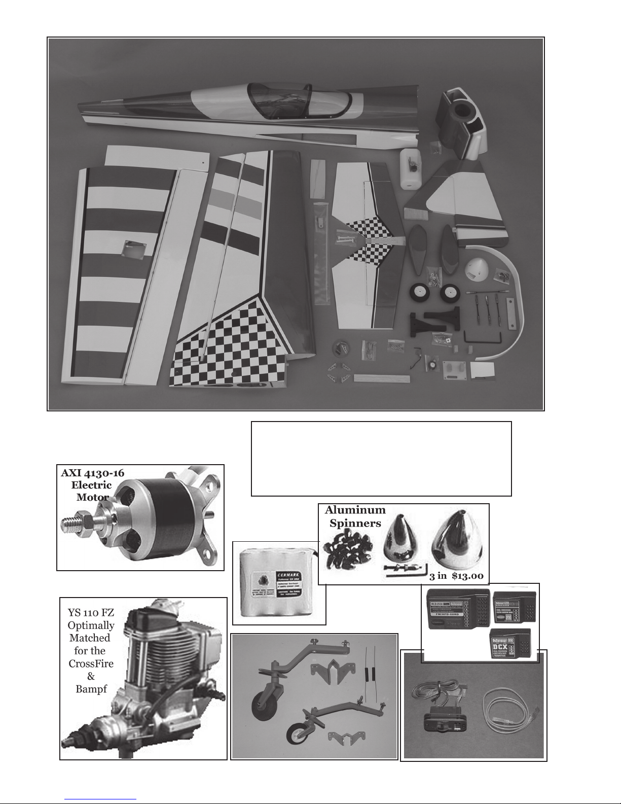
Bampf 3D Extreme Kit Components
Optional Equipment and
Accessories
Order these Optional Parts through: http://www.goldenskiesrc.com 1-866-429-2910

Table of Contents:
Kit Components Optional Equipment - Accessories ............................. ...... 2
Table of Contents ...................................................................................... 3
Introduction ............................................................................................. 4
SAFETY WARNING & DISCLAIMER ................................................... 5 - 7
Warranty Statement ................................................................................... 8
Recommendations ..................................................................................... 9 - 10
Tools and Materials Needed ...................................................................... 11
English to Metric Conversion Table .......................................................... 12
Quick Build Process (for experienced builders) ........................................ 12
Assembly Steps: ........................................................................... 13-34
Rapid Assembly Step Order .............................................................................. 12
Step 1: Aileron Hinge Installation .............................................................. 13
Step 2: Wing Servo Construction ................................................................. 14
Step 3: Wing Panel Joining .......................................................................... 15
Step 4: Engine Mount Installation................................................................. 16 -17
Step 5: Pitch Balance Check, Preliminary...................................................... 18
Step 6: Tail Assembly ................................................................................ 19
Step 7: Tail Surfaces, Elevator & Rudder ................................................... 20
Step 8: Fuel Tank Assembly ....................................................................... 21
Step 9: Aileron Final Assembly.................................................................... 22
Step 10: Aileron & Rudder Servo Installation................................................... 23 - 25
Step 11: Belly Pan Installation ....................................................................... 25 - 26
Step 12: Fuel Tank Installation........................................................................ 26 - 27
Step 13: Engine Installation.............................................................................. 27 - 28
Step 14: Cowl Installation................................................................................. 29 - 30
Step 15: Wheels & Landing Gear ................................................................. 31
Step 16: Battery & Switch................................................................................ 32
Spinner .......................................................................................................... 33
Decals ............................................................................................................ 34
Optional Assembly Steps: .................................................................................. 34 - 37
Balancing (Pitch-Roll-Yaw) ............................................................................... 38 - 39
Control Throws ................................................................................................. 39 - 40
Preflight Safety Checking .................................................................................. 40 - 41
Radio Controls .................................................................................................. 42
At the Field ....................................................................................................... 43
Flying ............................................................................................................... 43
Flight Trimming & Performance Chart ............................................................... 44
Supplemental Drawings and Figures ................................................................... 45
Engine Mount (rail separation) & Screw-Bolt Sizes and Drill-Tap Sizes ............. 46
Bolt, Screw and Drill Reference Chart ............................................................... 47
Evaluation Sheet and Mailer .............................................................................. 48
Disclaimer ........................................................................................................ 52-54
3

Introduction
We are sincerely pleased that you have purchased the Golden Skies R/C Aircraft (GSRC),
Bampf 3D Extreme ARF and we are sure you will thoroughly enjoy the Bampf’s ease of assembly
and flight performance. The final assembly manual is written in two sections:
1) For the very experienced builder of ARF type R/C models
2) For the relatively new builder.
For the experienced builder (one who has successfully assembled several ARF kits) we have
a fast build scenario listing the major building steps in a multiplexing order to facilitate a very rapid
build (5-6) hours. For the less experienced builder, we present you with a traditional, step-by-step
building process. For both experienced and less-experienced builders, GSRC recommends you
read the entire manual to get a feel for the building process and the instruction manual. This will
assist you in the building process. If you have any questions about how to build the Bampf 3D
Extreme, please either call or email GSRC.
Updated Assembly Manuals are available in Adobe © *.pdf format on our website. Enlarged
and extra assembly pictures are also available.
Golden Skies R/C Aircraft, Inc.
Laguna Niguel, CA 92677
949-429-2910
email: service@goldenskiesrc.com
http://www.goldenskiesrc.com
(page 12); and,
GSRC, Bampf 3D Extreme Features ......and benefits:
o Computer Aided Design (CAD) ...... ensures accurate, producible parts
o Strong, light weight design and construction ... High power to weight ratio
o Balsa and lite-ply construction ...... repairable with locally available materials
o OraCover ©, Heat Shrinkable Covering .... re-shrink, repairable
o After-Market Quality Hardware ...... The best available, a $35.00 retail value
o Pre-cut and Installed Canopy ...... A clean/accurate installation, time savings
o Pre-cut and drilled Cowl ......... For fast build and easy installation
o Pre-colored Cowl ....... long lasting color, fast build
o Heavy Duty landing gear ...... withstands rough landings
o Pull-Pull Rudder ........ Most positive control, easy adjustments.
o Dual, wing-aileron Servos ..... Low servo loads, quick control, reduced fluttering
o Continuously Taperedl Airfoil Tail ..... More positive rudder control, no flat stab seeking
o Fully symmetrical Airfoil Wing ..... Predictable, smooth, stable in any position
o Fast build Assembly manual ........ Fast build
o Warranted Firewall Strength ........ Reliability, peace of mind.
4
Safety Warning, Disclaimer and
ASSUMPTION OF RISK
Golden Skies R/C Aircraft, Inc.
Legal Agreements
Warning
The Radio Controlled (R/C), Almost Ready to Fly Aircraft (“ARF”) is NOT A TOY and is
potentially dangerous to property and individuals within several miles of your flying area. It
is capable of causing property damage, serious bodily harm, and possibly death if it strikes
personal property or an individual.
Consumer’s Responsibility
1) Assembly and Use
IT IS YOUR RESPONSIBILITY AND YOURS ALONE to assemble the ARF correctly and to properly install
all additional components, both included in the ARF kit and/or acquired by the purchaser of
this ARF; to preflight test the model; and to fly ONLY in an Academy of Model Aeronautics (AMA)
approved flying site with the supervision and/or assistance of a fully qualified flying site
instructor. The pilot of this ARF must comply with all of the AMA’s Safety Codes. The
employment of common sense for safety of yourself and others is otherwise mandatory. The ARF
has a radio range of 500 (or less) feet and the pilot is directed not to exceed this distance
when flying the ARF. In the event the range is exceeded, the pilot will lose control of the ARF
which could cause injury and damages to objects which the ARF may come into contact with upon
an uncontrolled landing. Do not attempt to fly this ARF if you have not been qualified as a solo
pilot by the instructor at the AMA approved flying site. It is recommended that on any first
flight of a new R/C aircraft that you attain the assistance or instruction of a highly
experienced R/C pilot to verify the ARF’s construction from a safety and flight perspective.
If you are just starting to fly R/C Model Aircraft of any type, consult your local Hobby Shop
or write to the Academy of model Aeronautics to find an experienced instructor in your area.
2) Assumption of the Risk
Participation in the operation of remote controlled aircraft is voluntary. I understand that
the operation of remote controlled aircraft is a dangerous sport which can result in bodily
injury, death, and/or damage to property for many reasons, including but not limited to
airplane accidents involving third parties known and unknown to the user; equipment failure,
malfunction, or misuse; weather conditions such as storms and lightning; the training, acts,
omissions, recommendations or advice given by your local Hobby Shop or the Academy of Model
Aeronautics concerning the operation of remote controlled aircraft and related activities such
as transportation to and from the site; and first-aid, emergency treatment or other services
rendered to me as a user or others. I understand and acknowledge that the above list of reasons
is not complete or exhaustive. I accept and hereby assume all risks of injury, death, illness
or disease, or other damage to myself, to others, or to my property which arise from participation
in the referenced activities.
5

3) Release
I hereby voluntarily release, and forever discharge GOLDEN SKIES R/C AIRCRAFT, INC., a California
Corporation, on its behalf and on the behalf of its successors and assigns, and each of them
(“Golden Skies”) and its subcontractors, and all other persons or entities associated with
it, including other participants, (hereafter collectively the released parties) from all
liability, claims, demands, actions or causes of action for bodily injury, death, illness,
disease or damage to myself, to any participating minor child of mine, or to my property which
are related to, arise out of, or are in any way connected with participation in the above
referenced activities, including but not limited to those arising from any negligent or
reckless acts or omissions or breach of contract of the released parties, or hidden defects in
the equipment used. This release is intended to be as broad and inclusive as is permitted by
California law, and shall be construed and interpreted under California law. If any portion,
clause or sub clause is held invalid, I agree that the balance shall continue in full force and
effect.
4) Maintain Proper Insurance Coverage
It is also mandatory that all R/C airplane pilots obtain adequate insurance through their own
homeowner policy or a separate policy to cover liability in the event of property damage or
injury to individuals or personal property. Additionally, all R/C airplane pilots must join
the AMA to become secondarily insured.
Academy of Model Aeronautics http://www.modelaircraft.org ….
Academy of Model Aeronautics
5151 East Memorial Drive
Muncie, Indiana 47302-9252
800-435-9262
5) Indemnification.
The user of this product agrees to indemnify and defend Golden Skies R/C Aircraft, Inc., a
California Corporation, as well as all employees, shareholders, directors, officers and agents
thereof ( “Golden Skies”) , against any claims, lawsuits or actions arising as a result of the
use of the radio controlled aircraft, and shall pay for all legal expenses incurred by Golden
Skies in connection with the defense of such matters, whether or not such claims are resolved
without trial or other final decision and whether or not such expenses are incurred in the
defense of litigation or simply incurred prior to litigation in connection with an informal
claim. The obligation of the user to indemnify Golden Skies is express and unequivocal. The user
is expressly obligated to indemnify Golden Skies for Golden Skies’ own negligence if any,
which may give rise to any claim arising in connection with the use or misuse of the aircraft
or components thereof
6) No reliance
I acknowledge that I am not relying on any oral, written, or visual representations or
statements made by the released parties, including those made in released parties catalogs or
other promotional material.
6

7) Venue
T
he Venue of any dispute that may arise out of this agreement or otherwise between the parties
to which Golden Skies or its agents is a party shall be Superior Court for the State of
California located in the County of Orange.
Return Policy
If you are not prepared to: 1) obtain adequate insurance to operate the ARF; 2)
accept all responsibility for personal property damage and /or bodily injury,
including possible death; and 3) to indemnify the ARF designer, manufacturer,
distributor and retailer for any liability resulting from your actions, return
the complete ARF kit to the point of purchase for a refund. In order to return
the ARF Kit, the following steps must be undertaken: ARF kit must be presented
in its original carton, undamaged and un-assembled. ARF must be in the original
OEM condition and suitable for resale. Purchaser must show valid purchase
receipt. ARF kit must be return to point of purchase with sixty (6) days of
original purchase. A restocking fee may be charged by the retailer. All
shipping and handling cost shall be born by the consumer/purchaser
Governing Law
Any legal action stemming from the purchase or use of this product will be governed by the laws
of the State of California and decided by a court of law in the State of California.
7
Warranty Statement:
Warranty
Golden Skies R/C Aircraft (GSR/C) warrants the ARF to be free from defect in both
materials and ARF assembly workmanship for six (6) months from the date of purchase
or the first flight, which ever comes first. GSR/C warranty does not cover the whole or
any component parts thereof damaged by use, misuse, modification, or crash of the
ARF plane. In no case shall Golden Skies R/C Aircraft be liable for the effect(s) of
incidental, consequential or indirect damages as the result of the use or flight of the
ARF product. The warranty is limited to the original ARF purchase amount and shall
not exceed that cost and explicitly excludes the cost of additional ARF and R/C components either installed in or used to construct the ARF that are not included in the original ARF kit. The GRR/C warranty is not transferable under any circumstances.
Governing Law:
Any legal action stemming from the purchase or use of this product will be governed by the laws of
the State of California and decided by a court of law in the State of California in the County of Orange.
Spare and Replacement Parts
Golden Skies R/C Aircraft stocks a complete line of Spare and/or replacement parts for your Bampf
3D Extreme ARF. We are trying to keep the replacement costs as low as possible, because we want you
to enjoy your Bampf with genuine, good looking, factory parts. So, please do not hesitate to replace
broken or worn parts and keep your Bampf in pristine condition. Consult your local hobby dealer and ask
them to order for you or order directly form Golden Skies R/C Aircraft at the address listed on the front
cover.
Bampf 3D Ex Part Number Sale
Canopy 10066-00001 $18.00
Cowl 10066-00002 $25.00
Wing (Set) 10066-00003 $125.00
Wing (Left) 10066-00004 $65.00
Wing (Right) 10066-00005 $65.00
Fuselage 10066-00006 $85.00
Landing Gear (Al) 10066-00007 $15.50
Decals 10066-00017 $5.50
Wheels 2-3/4” (2ea) 10066-00008 $7.00
Wheel Pants 10066-00009 $21.00
Tail Wheel Assy 10066-00016 $5.00
Metal Clevises 10066-00010 $7.00
Pushrod (set) 10066-00014 $15.50
Engine Mount 10066-00011 $6.50
Fuel Tank 16 oz 10066-00012 $5.50
Rx/Battery Switch 03080-00001 $16.00
Spinner (3” 03140-00006 $13.00
8

GSRC GENERAL RECOMMENDATIONS
- Work Area: Keep the work area clean and free of debris and unused tools. This will help
prevent damage to your model. If you set the kit components on tools or debris you can damage the parts.
Cover the work area with a soft cloth (bath towels work well) to prevent unwanted marring or damage to your
model.
- Step-by-step Assembly: If you choose to follow the step-by-step assembly process, check
off the boxes as you complete each assembly step. This will help you remember what is completed and
what remains to be done. Read each assembly step thoroughly and completely to be sure you understand
the assembly process prior to doing the actual assembly.
- Organization: Open the hardware bags as they are needed for assembly per the assembly
manual instructions. Once the hardware bags have been opened, place the parts in a small box or bowl to
prevent loss. You may need several small boxes to keep parts separate.
- Dry-Fittings: Always “dry-fit” all parts in each assembly step to check fit, alignment, and ease of
assembly. This will prevent any surprises when racing against a glue setting-time.
- Take Your Time: In the anticipation of flying your new GSRC model, do not be tempted to rush
the assembly process and put your plane or others at risk.
- Choice of Engines: The Bampf 3D was designed to fly with a strong “60-Size”, 2-Stroke
engine such as an OS-61FX ®. It will do all “sport-aerobatics” with great authority using the 60-size engine.
You may elect to install a 90-size, 2-stroke; however, it is more power than necessary to fly the Bampf 3D .
However, if you want to “stick-n-rudder” (SnR) the airplane, the 90 (2/s) or 120 - 140 (4/s) will add to the “3D” and “FreeStyle” capability typical of SnR flying styles.
You may also choose to use a 90-size 4-stroke engine, such as an OS-91FS ® or equivalent. The 904/s is roughly equivalent to the 60-2/s but has more torque and can accommodate a larger prop. A 140-4/
s is, again, more power than necessary, but a lot of SnR fun. Take care to balance your props and perform
other routine vibration dampening procedures. Vibration in the fuselage, wing and other structural parts will,
in time, weaken your airplane to the point of failure.
- Balance your Props: Always, balance your props. Follow the engine manufacturers recom-
mendations for prop size, and balance the prop. Vibration is your models enemy and will eventually cause
structural failure. The worse and more prolonged the vibration, the sooner the failure will occur. This is true
of all aircraft, whether they be full-size or models.
- Servos: GSRC recommends high quality, ball-bearing servos with either metal gears or high
reliability, resin-composite gears. Metal gears will add weight to the plane, so the resin composites are a
good alternative. Use this type of servo on all control surfaces; however, a “standard” servo is suitable for
the throttle control. GSRC recommends 80-90 in-oz.. torque for elevator and 90-125 in-oz. torque for
rudder whereas you can use 75-85 in-oz (minimum) servos for each wing-aileron servo. As a minimum, the
Hitec © HS-635HB is a good servo and can be used for all control surfaces, the HS-625MG or HS-645MG
are good for the rudder, and the HS-325HB is suitable for the throttle. Hitec servos may be ordered through
the GSRC website ...... http://www.goldenskiesrc.com.
9
Recommendations Continued
- Batteries: 4.8 V, 600 mAh batteries are typical in sport model aircraft, however, GSRC prefers
to use 6.0 V, 1100 mAh batteries for higher torque and greater servo actuation speed. The 6.0 V battery is
heavier by one “cell” (5- vs 4-cells), but GSRC believes in highly aerobatic aircraft such as the Bampf, you
will be more satisfied with the 6.0 V performance. Also the higher voltage “tends” to provide for better noise
immunity in the receiver, and the 1100 mAh tend to provide for more flying time than a 600 mAh.
- OraCover © Heat-Shrink Covering: OraCover is absolutely the best heat-shrink
covering available of its type. It is durable, repairable, replaceable and re-shrinkable as needed.
normal for the covering to show wrinkling from time to time. As temperature and humidity changes, the
balsa will expand and contract. This is natural and the covering may wrinkle. Simply re-shrink the covering
using a covering heat gun. Heat guns are available from your local hobby dealer.
We suggest the you
re-iron all the trim covering before you assemble the Bampf to assure it is attached.
- Radios (Tx & Rx): All of the name brand radios are good, and GSRC prefers you use the radio
you are most accustomed to and comfortable with. The Bampf will require four Channels minimum and
possibly a 5-channels if you split your ailerons for flaperon capability. It is a good practice to keep the
Transmitter and Receiver to the same brand; however, servos of a different brand are a generally accepted
practice and should cause no problems. Always check your radio manufacturer’s recommendations. Be
aware that different radio receivers may require a specific servo plug-type to be both mechanically and
electrically compatible.
It is
- Conventions: When the manual refers to left and right, it is in reference to your left or right as
viewed from the fuselage tail looking forward or as if you were sitting in the cockpit. Generally, when
“Increasing a Function” of any entity (such as battery switch, a servo, etc.), the following conventions should
be observed:
- Forward
- Clockwise
- To the right
- Up
Doing the opposite of the above, is considered “Decreasing the Function”
- What you need to complete the Bampf 3D Extreme.
- Two 18” Servo Extensions,
- One “Y-harness” servo cable
- One 24” Servo Extension
- One Engine, glow-plug, muffler and suitable propeller
- Five - six (5-6) Servos
- Fuel Tubing, 16-20 inches
- “Fuel Plug” or fuel fulling valves (optional)
- Foam Rubber to pad fuel tank, as desired
- Receiver, 4-channel minimum
- Battery, 6.0 V, 1100 mAh
- Battery Switch, super switch (See page 2)
10

Tools and Supplies Needed:
The following items will be needed to complete the final assembly of the Bampf 3D Extreme
ARF. The assembler should acquire all needed supplies prior to starting assembly and become
familiar with each item by thoroughly reading the manufacturer’s directions.
Materials:
- C/A medium viscosity adhesive, any brand
- C/A thin viscosity adhesive, any brand
- Epoxy, both 5-minute and 30-minute (2000 pound shear), 2-part epoxy
- C/A Debonder, 1-0z
- Acetone, pint or quart
- Denatured alcohol, pint or quart
- Mixing cups, 1-0z
- Silicon Caulking, white (optional)
- Fiberglass (2-0z) and polyester resin (Optional)
- Clear, polyurethane spray, fuel proof
Tools:
- # 0, # 1 and # 2 Phillips head screw drivers
- # 1 & # 2 Flat blade screw driver
- Adjustable Wrench
- Needle Nose Pliers
- Modeling knife, # 11 blade
- Single edge razor blades
- Electric drill, 1/16” to 1/4” bits in 1/32” increments
- Modeling T-pins
- Sandpaper, 180 to 220 grit
- Dremel © “Moto-Tool” ®, wheel cutter, drum-sander, coarse and fine
- Paper towels and/or soft rags
- Pencil and/or felt tip pens (Sharpie ®)
- Ruler, scale
- Toothpicks
- Center Punch
- Hex driver set, Metric and English
- Nut driver set,
- Clamps, variety (see assembly pictures)
- Epoxy brushes, (Solder flux brush)
- T-square or triangle square
- Incidence Meter, Robart ® Model # 404 Incidence Meter
- Rubber bands, # 64 or stronger
- Covering/sealing iron and/or covering heat gun
11
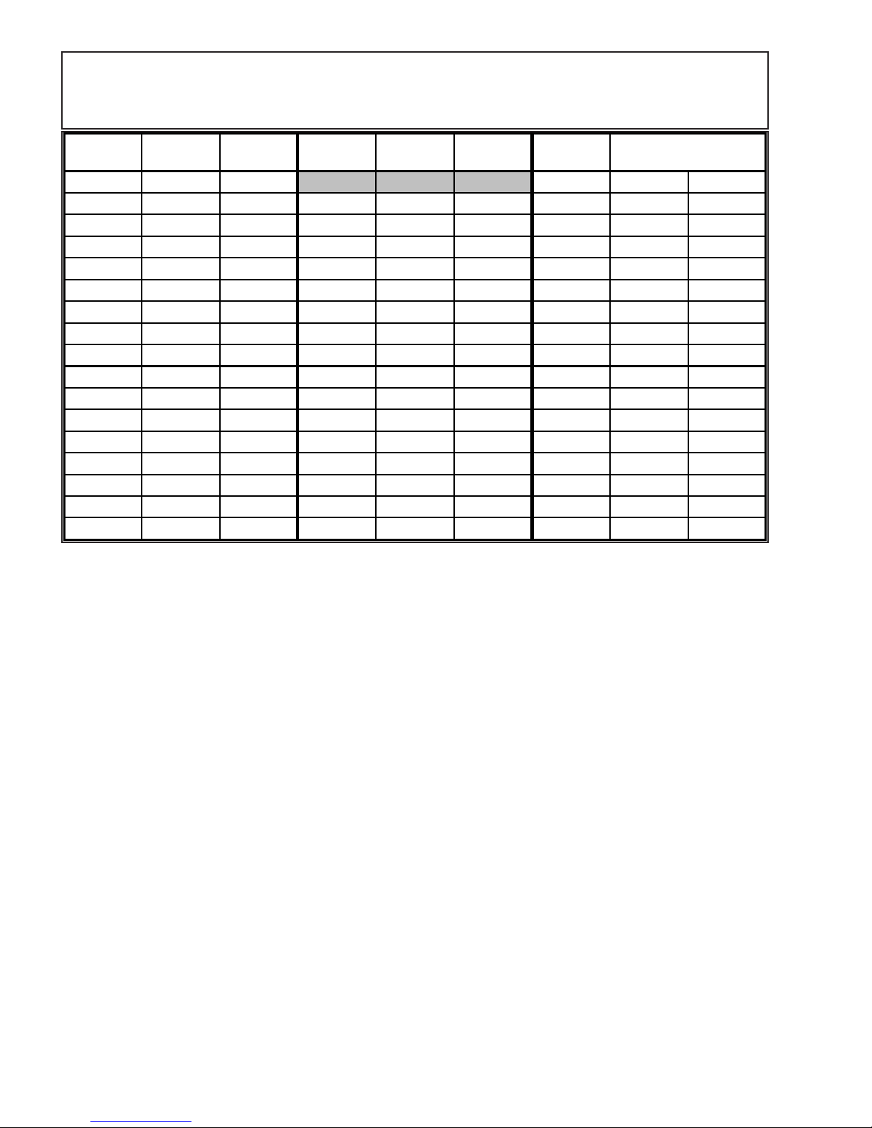
Table 1: English to Metric Conversion Chart
English
(in)
1/64 0.4 0.04 1 25.4 2.54
1/32 0.8 0.08 17/32 13.5 1.35 1.5 38.1 3.81
1/16 1.6 0.16 9/16 14.3 1.43 2 50.8 5.08
3/32 2.4 0.24 19/32 15.1 1.51 2.5 63.5 6.35
1/8 3.2 0.32 5/8 15.9 1.59 3 76.2 7.62
5/32 4.0 0.40 21/32 16.7 1.67 3.5 88.9 8.89
3/16 4.8 0.48 11/16 17.5 1.75 6 152.4 15.24
7/32 5.6 0.56 23/32 18.3 1.83 9 228.6 22.86
1/4 6.4 0.64 3/4 19.1 1.91 12 304.8 30.48
9/32 7.1 0.71 25/32 19.8 1.98 18 457.2 45.72
5/16 7.9 0.79 13/16 20.6 2.06 21 533.4 53.34
11/32 8.7 0.87 27/32 21.4 2.14 24 609.6 60.96
3/8 9.5 0.95 7/8 22.2 2.22 30 762.0 76.20
13/32 10.3 1.03 29/32 23.0 2.30 36 914.4 91.44
7/16 11.1 1.11 15/16 23.8 2.38 40 1016.0 101.60
15/32 11.9 1.19 31/32 24.6 2.46 48 1219.2 121.92
1/2 12.7 1.27 1.00 25.4 2.54 62 1574.8 157.48
Metric
(mm)
Metric
(cm)
English
(in)
Metric
(mm)
Metric
(cm)
English
(in)
Metric
(mm)
Metric
(cm)
Quick Build Step Sequence:
For very experienced builder, follow the building sequence below and refer to the
appropriate pictures or narrative as needed for assistance.
1. Epoxy hinges into all control surfaces
2. Construct the aileron wing servos
3. Install the engine mount
4. Join the wing panels together
5. Install tail surfaces
6. Assembly the fuel tank
7. Attach control surfaces
8. Install nose wheel
9. Install all servos, push-rods, pull-pull rudder system
10. Attach belly pan
11. Install fuel tank
12. Install engine.
13. Install cowl
14. Attach wheels
15. Install Radio Gear
16. Attach Spinner
17. Attach Decals
18. Perform preflight checks
Following this sequence, one should be able assemble the Bampf 3D in 4-8hours.
12
Step 1: Hinge Installation for Aileron Surfaces:
In this step, you will install all the hinges into the Ailerons. There should be Eight (8)
hinges in all. You will need a lightly grease, the 8 hinge joints to prevent the epoxy from
entering the hinge point. Epoxy the hinges only into the aileron surfaces.
While the epoxy is curing, move on to Step 2.
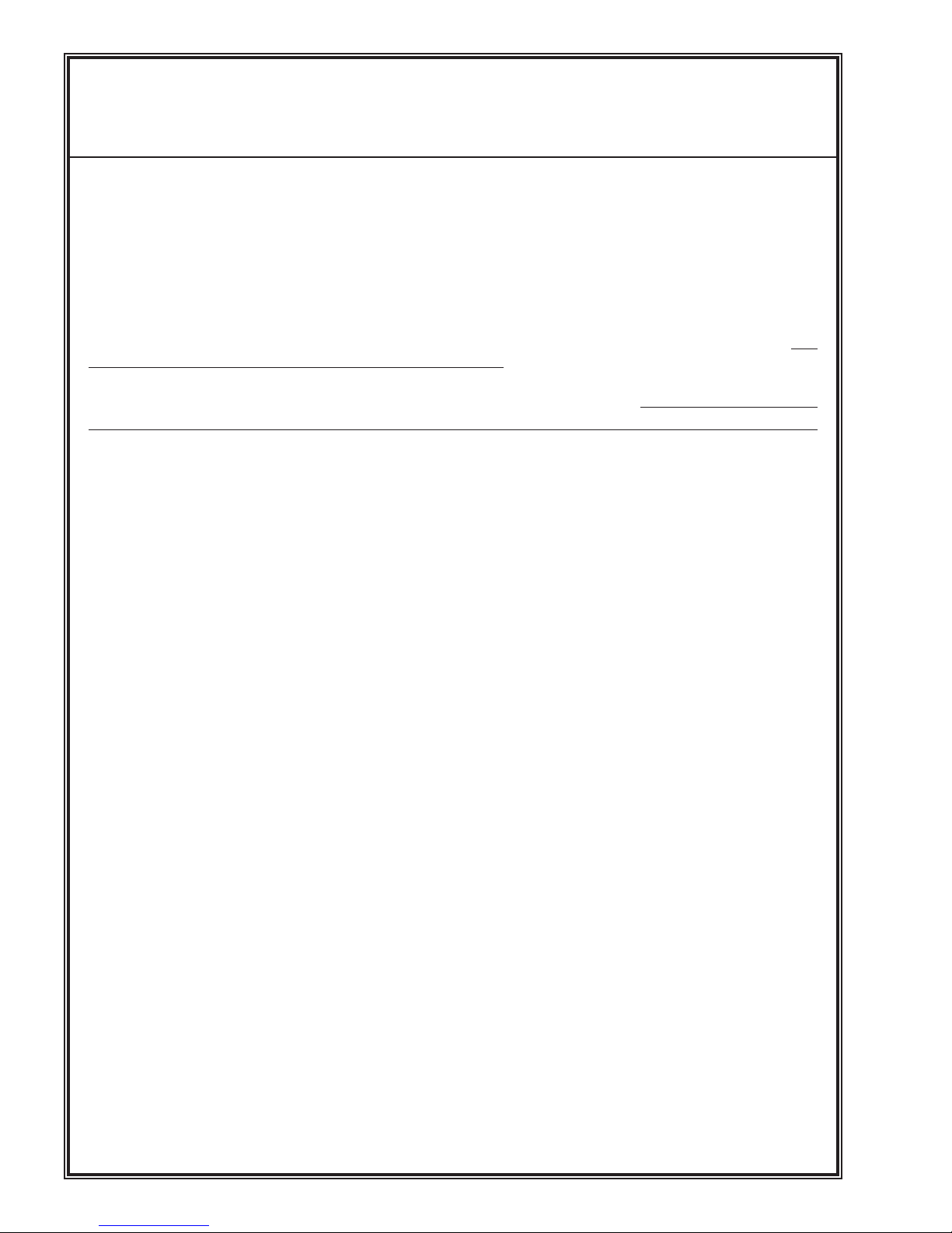
Dry Fit Control Surfaces:
Place the hinges into the aileron control surface hinge-holes and
slip the assembly into the wing. Check for fit and alignment. There
should be no appreciable gap at the hinge line. The hinges’ metal pins
should be at the control surface’s hinge line or pivot point. When
satisfied, continue. Mark the ailerons to know which wing panel they
go on.
Grease Hinge Area:
using a light grease such as Vaseline, lightly cover the entire hinge
joint area to prevent the epoxy from entering the hinge joint. Take
care not to get grease on the ribbed hinge shank area where it will be
glued into the control surface.
CAUTION: Do not use Oil !
Apply Epoxy to Hinge Hole:
Mix an ample amount of 2-part, 30-minute epoxy following
the epoxy manufacturer’s directions. Apply a sufficient amount, using
a toothpick to the aileron hinge hole and allow to settle into the hole.
Wipe off any excess epoxy from the surface.
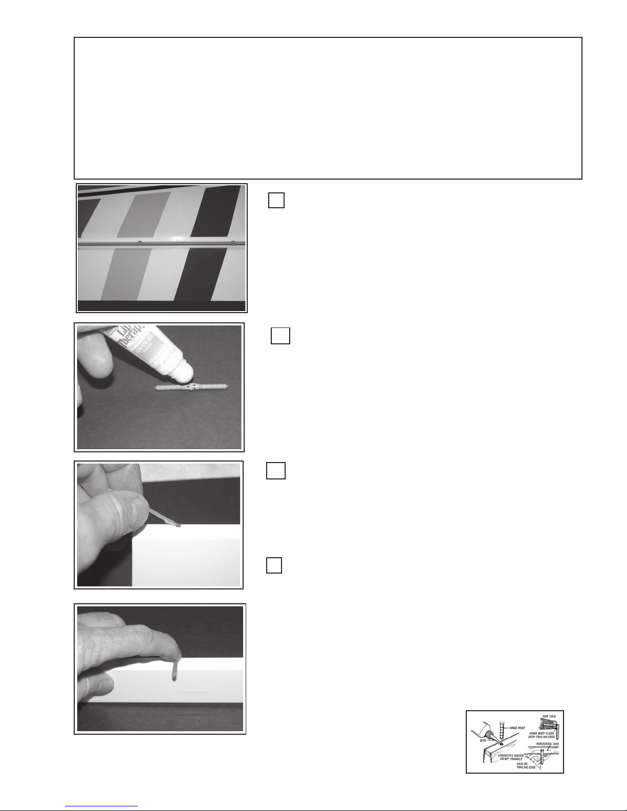
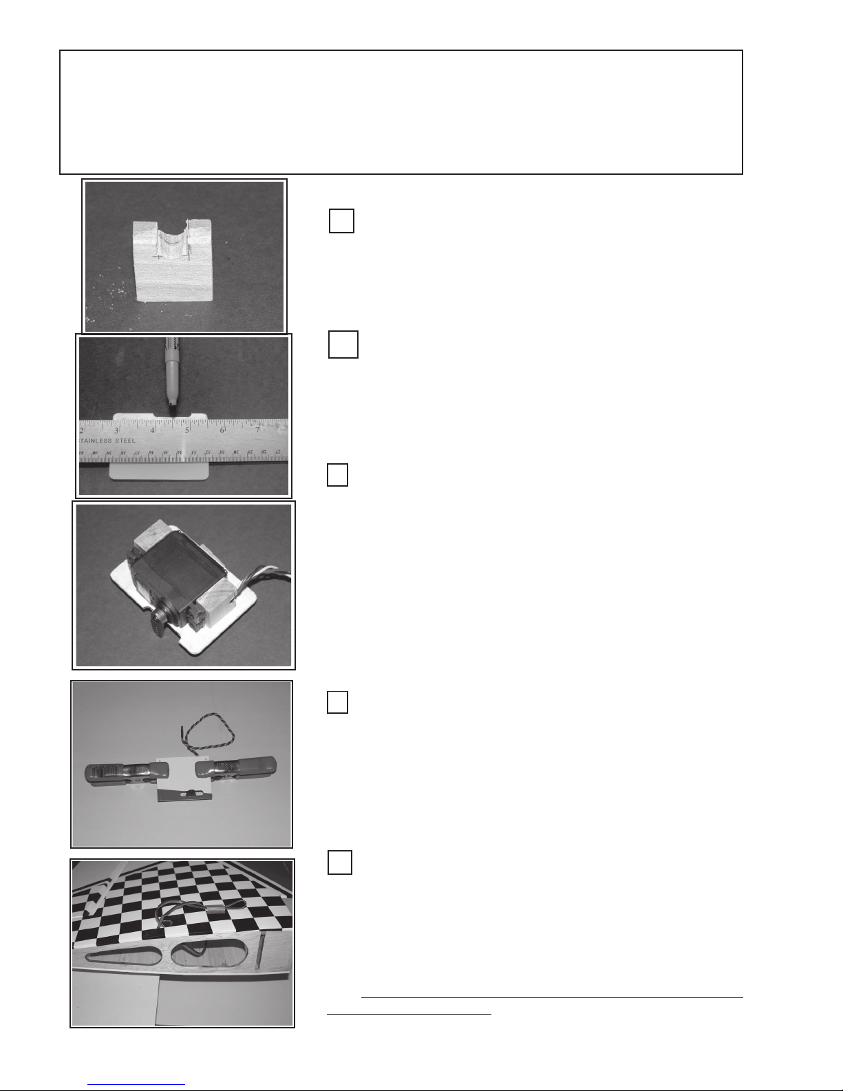
Insert the Hinge:
Insert the Hinges into the control surface’s hinge hole. Press the
hinge sufficiently into the hole so that the metal hinge pin is in-line
with the control surface’s hinge point or line. Bend the hinge as shown
in the picture (left) so that the free hinge arm is perpendicular to the
control surface’s hinge line. This will assure that the hinge axis is inline with the control surface’s hinge line. Apply epoxy to the corresponding wing hinge-hole and slip the four hinges into the wing and
push the aileron into place with minimal gap between the aileron and
the wing. Secure with masking tape in three place to hold aileron in
place. Allow epoxy to cure.
Courtesy of Robart, Inc
13
Step 2: Wing Servos & Servo-Wire Extensions:
In this step you will be installing the wing-servos onto the wing-servo access covers and placing the
wing and elevator servo-extension cables in the wings and fuselage respectively.
Hardwood Mounting Blocks:
Locate the four hardwood servo-mounting blocks. In two of the
blocks, cut a notch ~ 1/4” x 1/4” to accommodate the servo wire. A
1/4” rat-tail file works well for this job. Round the edges of the cut
to prevent abrading or cutting the servo wire. Make sure the cut is
oriented such that the servo screws will go in the block’s cross-grain.
Prepare the wing-servo Access Covers: On both
wing servo covers, measure the width of the opening-notch
and mark the center of the opening. You will be aligning the servo
arm with this mark. Marking both sides will make it easier to align the
servo. The servo-cover only goes on one way. Please observe that
the notches face toward the wing tips; therefore, the servo-arms in
each wing panel face in opposite directions; i.e.; toward the wing tip.
Mount Servo to Hardwood Blocks:
Place the wood servo blocks against the servo mounting tabs as
shown left. Place 2 - 3 pieces of 20 pound paper beneath the servo
to raise it slightly off the surface . While holding the blocks against
the servo mark the mounting holes with a pencil or a punch. Predrill
the blocks with a 1/16” drill bit and mount the servo to the blocks
using the servo manufacturer’s supplied screws.
Now is a good time to mechanically center the servo arms.
Connect the servo to the receiver’s aileron port and turn on your receiver and transmitter. With the aileron controls (stick, trim, subtrims, centering) set to neutral, mechanically mount the servo arm on
the servo shaft, such that it is perpendicular or square with the cover
surface. Repeat this process for both wing servos.
Epoxy Servo Blocks to Cover Plate:
Remove the paper spacer from under the servo and place a
piece of wax paper between the servo, the blocks and the cover plate
to prevent epoxy from getting on the servo. Realign the servo and
mark its position. Mix the two-part, 30-minute epoxy and apply to the
block, reposition the servo on the cover and clamp. Set aside and
repeat process on the other wing servo. Remove wax-paper when
cured. Install the Servo-block safety screw, after curing.
Install Servo Extension Cables:
Locate the servo extension cable-hole on the top of the wing
near the root rib. In not already cut out, cut an “X” in the covering over
the hole. Hold the wing vertically, with the tip down and feed the 18”
extension wire through the wing and into the servo box. Dress the
cable through the hole and tape-off both ends so that you do not lose
the wire. Be sure to note the “sex” of the connectors so it will mate
with the servo connector. (The Female cable-end goes into the servo
box.) You may use the string-pulls in the wing to assist in getting the
extension through the wing, either works.
14
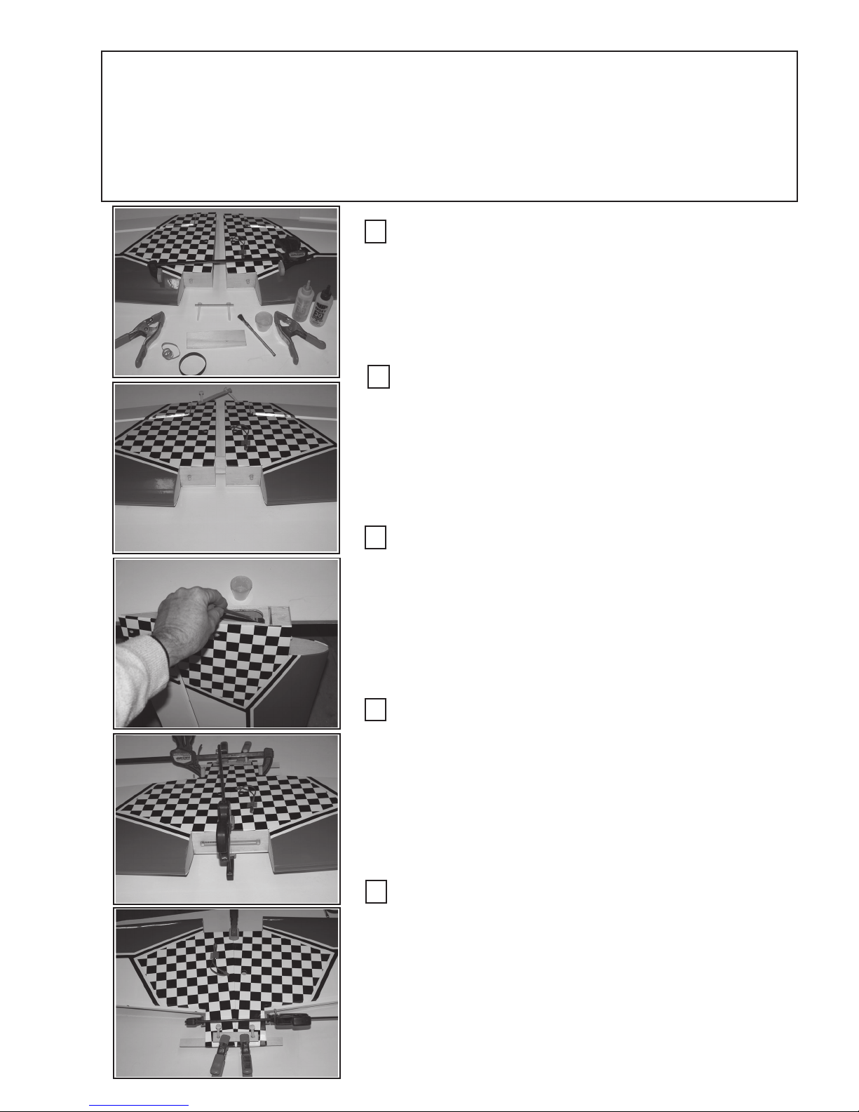
Step 3: Join Wing Panels:
Gather together the following items: Wing panels (2); dihedral brace; 2-part, 30minute epoxy; epoxy brush; mixing cup, clamps (4); rubber bands #64; 2 ea 6” bar clamps;
2 pieces of scrap lite plywood (~ 1” x 8”), wax paper. Be sure you have placed the wing
servo-extension cables in the wing as described in step 2.
Gather and Layout Wing Panel & Materials:
Assemble the materials as described above on a flat surface at
least 60” long. You will need at least six (6) each # 64 or stronger
rubber bands. Also have handy the wing bolt backing strip (~ 1/8” thick
lite-ply with two 1/4” holes in it) and the 1/4” nylon wing mounting bolts,
and the bar clamps. Make sure ailerons are removed from wing.
Dry Fit to Check Fit & Alignment:
Measure and mark the center of the dihedral brace. Dry fit the
Dihedral Wing-Brace into the wing-box and push the two wing panels
together to check for proper fit and alignment. The top, bottom and
wing edges should align evenly and the root rib of each wing panel
should fit perfectly flush to each other. When you are satisfied with the
fit, proceed to next step.
Apply Epoxy and Assemble:
Mix a generous amount of 30-minute epoxy and using the epoxy
brush, apply a liberal amount of epoxy into the wing-box, one-half of
the dihedral brace and fit the brace into the wing box up to the center
mark. Apply epoxy to the surface of the root rib. Repeat for the other
wing panel..... be sure to epoxy both rib roots. Slide the two wing pan-
els together.
Check Fit and Secure Wing Panels:
Place at least six (6) rubber bands (or bar clamp) over the wing
dowel pins and the aileron shoulders to draw the wing’s leading edge
together. Check to make sure the fit is correct and all surfaces align
and match flush. Wipe off any squeezed out epoxy using a rag and
denatured alcohol as necessary.
NOTE: Removal of covering to install belly pan. You may
place the belly pan on the wing bottom, while the wing is on the fuselage, draw a line along edge of pan, cut only through the covering and
remove covering material.
Secure Trailing Edge:
Using the wing-bolt plate, insert the two wing-bolts through the
plate and then through the holes in the wing. Use a bar clamp in the
aileron shoulder. It may be necessary to push the panels together by
bracing one wing-tip against a solid object and applying pressure to the
opposite wing tip to push them together. Using the two scrap pieces of
lite-ply, place one on the top and one on the bottom of the wing at the
trailing edge. Clamp in place. (See Optional Assembly Step:
“Fiberglass Wing Bottom” ... “WPFG-1”, on page 34)
15
Step 4: Assemble the Engine Mount:
Although GSRC had intended to have the engine mount blind-nuts pre-mounted, but in order
to provide the assembler with the most engine mounting flexibility we allow the assembler to
decide the engine mount orientation. We will show how to side-mount an engine. We will be
showing an YS-110FZ®; however, the procedure will be similar for other engines. Take note and
pre-plan for the mounting and thoroughly consider the implications of the muffler and needle
valve locations.
V
There is ~ 2° right thrust offset built into the fuselage firewall.
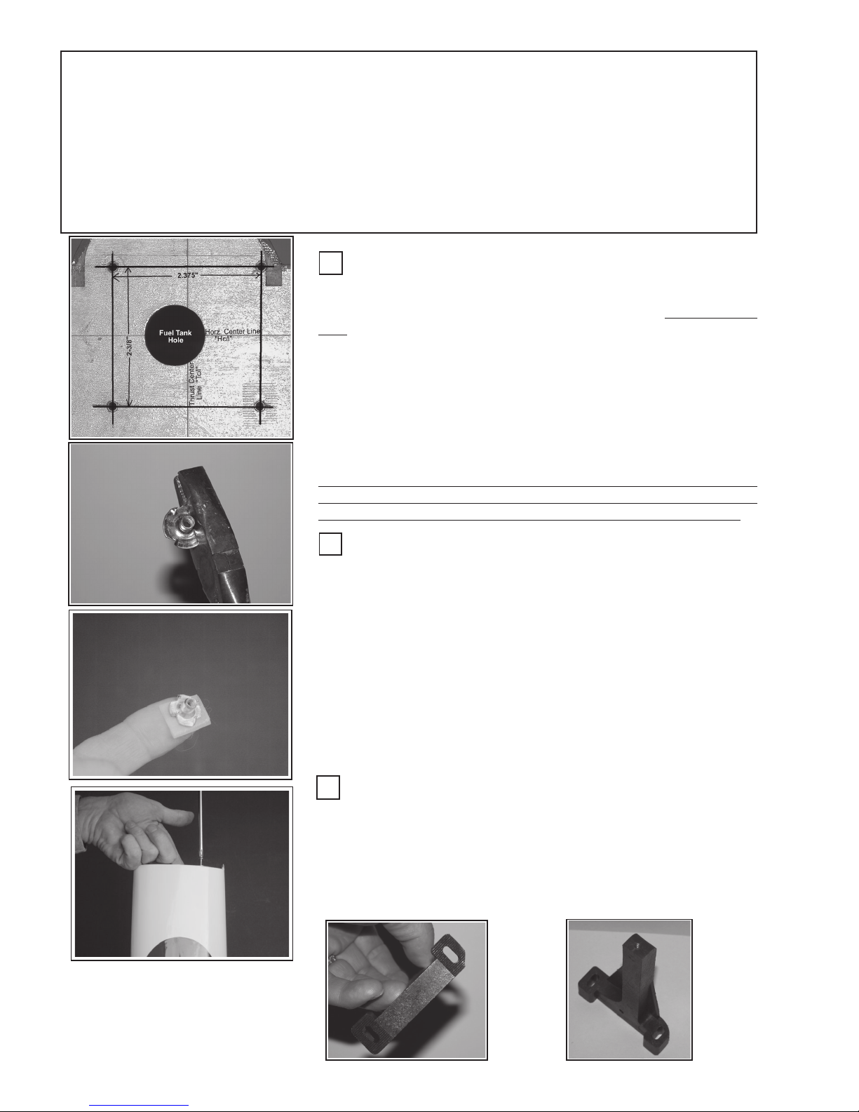
Locate the Engine Mounting Holes:
Locate the Horizontal (Hc/l) and Thrust Center Lines (Tc/l). If they
C
F
are not visible, measure and draw them in. Draw two (2) parallel lines,
one 1-3/16” to the right and the other 1-3/16” left of the Thrust Center
Line .
The distance the two engine mount rails are to be set apart is dependant upon the engine you will be using. Refer to Table 2, (p 46) for
specific engine details. If you engine is not listed, measure the engine
crankcase width just below the engine’s mounting tabs. Add 0.350” to
this dimension (the result will be termed “A”) and then divide the number
“A” by two (2). The resulting distance will be termed “B” Draw two (2)
parallel lines, at “B” inches above and below, Hc/l. Where the four lines
cross, center punch and drill 13/64” diameter holes for the blind nuts.
Depending upon the size and type engine you use, you may need to
rotate the entire bolt-hole pattern 2-3 deg. CCW to get the engine inside
the cowl. Do this now if you have any doubts if the engine will fit in.
Install Engine Mount Blind-nuts:
Cut the side off one of the blind nuts as shown. This nut goes in the
upper-left corner. Place a washer on one of the engine-mount bolts and
have it and a 7/16” hex-driver at hand. Using a piece of tape, make a
loop and stick it to the end of your index finger. Place a blind-nut on the
tape as shown, left. Orient the blind-nut through the fuel tank hole and
under one of the firewall bolt holes. Using the engine-bolt & washer,
thread the bolt into the blind-nut. Tighten with the hex-driver to draw
the blind-nut into the back side of the firewall. Repeat this process
for the remaining three engine-mount holes.
Note that the firewall has been marked with the fuel-tank tubing information. Refer to the fuel tank assembly step for fuel-tank tubing (port) orientation.
The markings refer to: 1) Muffler or Vent port, 2) Carburetor port, 3) Fill
port (the 3rd filling port is optional)
Modify Upper Mount:
Cut of the corner of the upper engine mount as shown and
check fit on the firewall to be sure the mount will fall within the firewall
perimeter. Temporarily attach the engine mounts using the four
engine mounting bolts and washers. Snug it down tight; however, it
will be removed later to drill the engine mounting holes in the engine
mount rails.
16
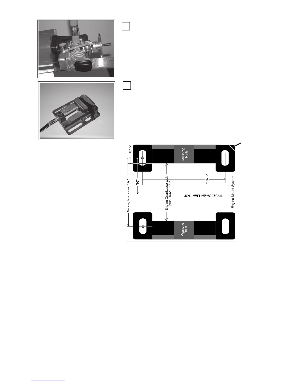
Locate Engine Position:
With the spinner’s backplate on the engine shaft, clamp the engine
to the mount-rails, as shown. Position the engine so that the rear edge of
the spinner backplate is 5-5/8” from the firewall front surface. Be sure
to measure all the way around the backplate to be sure the backplate is
parallel with the firewall and everything is centered and “squared-up”).
With the engine securely fastened, mark the engine mounting hole on
the mount-rails, using a pencil or center punch.
Drill Engine Mounting Holes:
Center punch the engine mounting hole locations that you marked
above and place in a drill-press vise or bench vise. Drill the engine
mounting holes for the size of bolt recommended by the engine manu facturer. Attach the engine mount to the firewall. Do not mount the
engine at this time (For 60 - 120 size engines, use # 6-32 steel bolts
(minimum), and locking nuts on each engine bolt.)
Round off
this corner
17
 Loading...