

Goldenote Stibbert Black Pearl III Owner's Manual

Goldenote®
Stibbert
Black Pearl III
ITALIAN PRESTIGE CD PLAYER
Owner’s Manual
MANUFACTURED IN ITALY
TEL.+39.0571.675005 !FAX.+39.0571.675013
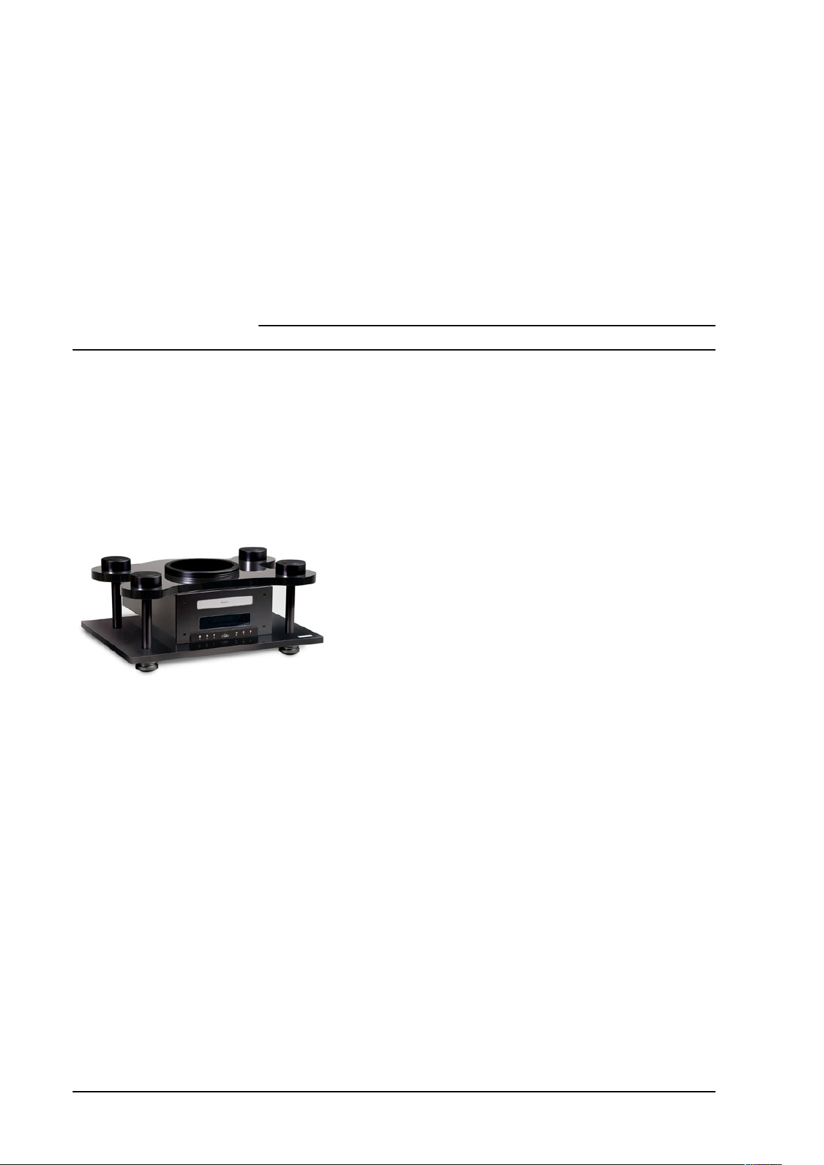
Stibbert Black Pearl Italian Prestige CD Player
Table of Contents
- Congratulations & Introduction !3
- Contents of Packaging - Construction Features ! !4
- Set-Up Instructions - Positioning – Operating Conditions ! !4
- Operating Conditions !5
- Remote Control Function !6
- Technical Specifications ! !7
- Warranty, Customer Service, Warnings & F.A.Q. !8
- Troubleshooting !9
VERY IMPORTANT: !Please read the following instructions carefully before installing your
Goldenote® CD Player
Stibbert Black Pearl Italian Prestige CD Player
CongratulationsCongratulations
Thank you for having purchased a Goldenote® product.
IntroductionIntroduction
Goldenote® designs & manufactures 100% in Italy a range of
prestigious high-end audio products featuring unique,
technical and aesthetic characteristics.
The Diamond line is the Goldenote top available technology featuring the
best possible solution and skilfully handmade products.
The Stibbert Black Pearl is one of the best CD player of the state-of-theart Diamond Line, featuring top class design in digital and analogue stage
but even one of the most massive power supply available for a CD player
unit.
The analogue stage of the SBP is powered by a triple transformers power supply featuring the highest audio performance.
The very high mass suspended on springs chassis is also able to control the energy of vibration feedback featuring a high
class cosmetic as well.
The internal DAC uses a proprietary filter that enables the unit to reproduce a very large bandwidth with low signal
compression.
The new Electro-Power™ voltage power supply of the is the first automatic servo assisted power supply installed in a
consumer CD Player. The Electro-Power™ also allows the unit to have an electronic stability particularly efficient.
The transport mechanism is of the drawer type made of aluminium it enables the smoothest possible rotational stability
reducing the speed fluctuation as well.
Congratulations & Introduction !3
Stibbert Black Pearl Italian Prestige CD Player
Contents of PackagingContents of Packaging
- 1 CD PLAYER HIGH MASS UNIT FIXED ON A POLISHED BLACK ACRYLIC PLINTH
- 1 BLACK BASE PLINTH
INTO THE TWO BOXES ASIDE THE MAIN UNIT:
- 1 REMOTE CONTROL
- 4 BRASS THREADED BARS FOR CDP SUPPORT COMPLETE WITH RUBBER SPACER RINGS and threaded, adjustable, aluminium spring supports..
- 4 CONICAL SPRINGS FOR CDP ACRYLIC PLINTH SUPPORT
- 4 THREADED BAR COVERS
- 4 SEMI CONICAL ANODIZED ALUMINIUM FEET
- 4 ROUNDED ANODIZED ALUMINIUM SPRING COVERS 70mm circa LARGE
- 1 DETACHABLE AC POWER CHORD
- DUMBO AC EXTERNAL POWER SUPPLY
- INSTRUCTIONS MANUAL
Construction featuresConstruction features
This section describes the special features of the CD Player, the construction features, the reasons for the technical choices and the originality of the design.
• The STIBBERT BLACK PEARL is a floating on Harmonic Iron springs CD Player that uses a plinth made of black high-density polished acrylic, an High-Mass metal main electronic cabinet. A clear acrylic plinth as support the whole
structure.
• The chassis is particularly heavy to help dissipating vibration feedback.
• The TUBE features two 6DJ8/6922 Tubes on the output stage
• The Dual-Speed™ system enables the unit adjust the disc rotation speed depending on the effective need improving the laser track ability.
• The Electro-Power™ allows a precise and fine voltage setting in any specific critical area of the electronic circuit where variations may affect the sound quality.
• The Zero-Clock™ fight the jitter digital problem rephrasing the Clock of the unit.
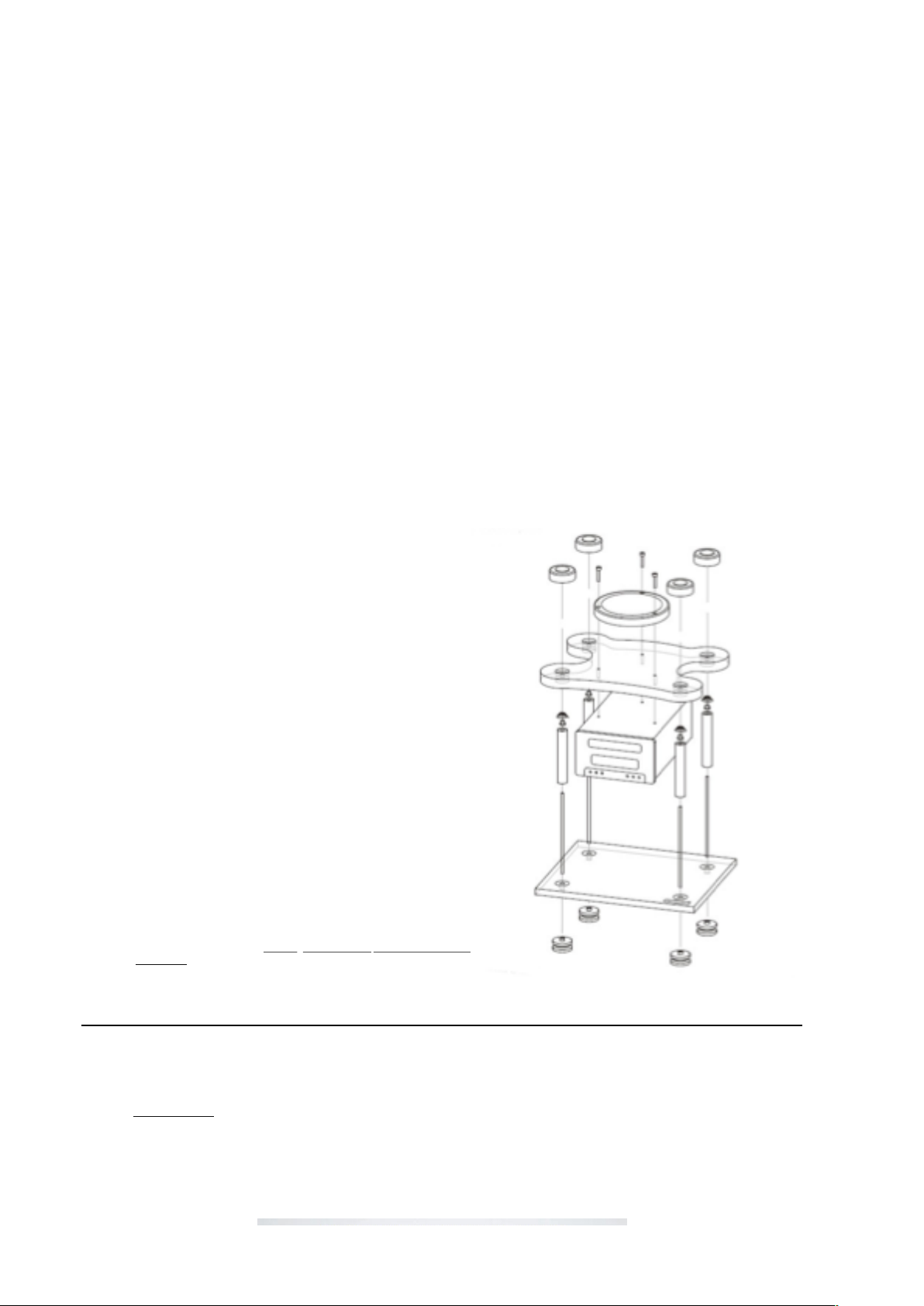
Set-Up InstructionsSet-Up Instructions
Open all the cartons inside the main box and check that all the components listed in the
“content section” are present.
1) Carefully remove the STIBBERT Black Pearl CDP chassis from the shipping box as
well as the 2 carton boxes and the clear acrylic plinth
2) Screw down the four threaded bars in the specific holes of the transparent acrylic
plinth. The threaded bars must protrude from underneath (the other side of the
Clear plinth Goldenote® label and grey rounded velvets) the transparent acrylic
plinth about 10 mm.
3) Screw up the silver anodised aluminium feet on the threaded bars onto the lower part
of the transparent acrylic base.
4) Insert the silver anodised aluminium threaded-bar covering columns over the
threaded bars on the upper part of the transparent acrylic plinth. Please note that
the rubber ring spacers should be left in place and the covering columns slid over
them. It is normal to encounter some resistance when doing this, because the
rubber ring spacers are there to prevent the covers from moving when you have
completed the installation.
5) Screw the bolt shaped spring supports onto the head of the threaded bars with the
bolt/smaller cylindrical shape facing up and fit the conical springs onto them with
the narrow part of the spring at the top. The spring support should be screwed
down close to the head of the threaded bars.
6) Gently lay the CD player unit onto the pre-installed springs finding the perfect
cente–ring inside the holes of the plinth itself.
7) Place the STIBBERT Black Pearl on the level surface you have chosen for it. We
recommend a wall shelf, as they are the sturdiest, and immune to footfall, but a
well made equipment rack should also give satisfactory results. You are now ready
to make the necessary connections.
8) Connect the respective left and right channels of your Interconnect cables to your
amplifier (or a digital 75ohm cable if you are using an external DAC).
9) To finish the installation level the unit to a perfectly flat position and connect the
supplied AC Power chord. Levelling the unit will provide the best sonic
performance.
Contents of Packaging - Construction
Features !4
Stibbert Black Pearl Italian Prestige CD Player
Operating ConditionsOperating Conditions
1) Level carefully the unit on a solid shelf properly aerated to let the unit cool down.
2) Connect the audio cable (not supplied) to the amplifier. Note that the unit can be connected to RCA unbalanced analog output or to the Balanced XLR analog output
but not both at once.
3) The unit features a 75ohm coaxial digital output for eventual connection to external Digital/Analog converters.
4) Connect the AC chord supplied.
5) The Master Switch of the unit is put on the back panel. The front panel switch works exclusively as stand-by leaving the unit partially on.
6) To change the tubes open the back panel removing the screws indicated on the picture below
Once the has been correctly assembled and positioned on a solid shelf and fully wired the player is ready to play.
The front Panel replies six basic function of the unit:
STAND-BY - It turns the unit in a Stand-By mode only. To turn off the unit completely the Master Switch on the back panel must be turned off.
STOP
SKIP Forward Skip the track. Keeping pressed the unit searches on the track listened FFW.
SKIP Reverse Skip the track. Keeping pressed the unit searches on the track listened RWD.
PLAY It lets start playing the disc. Pressing again the PLAY button the unit turn into the PAUSE mode then continuing pressing the button the unit turns Playing and
Pausing alternatively.
OPEN/CLOSE
The CD Player must be kept OFF at least 30 seconds before turning it ON again otherwise it may get in protection the unit freezing up all the
functions.
Set-Up Instructions - Positioning – Operating Conditions !5
Stibbert Black Pearl Italian Prestige CD Player
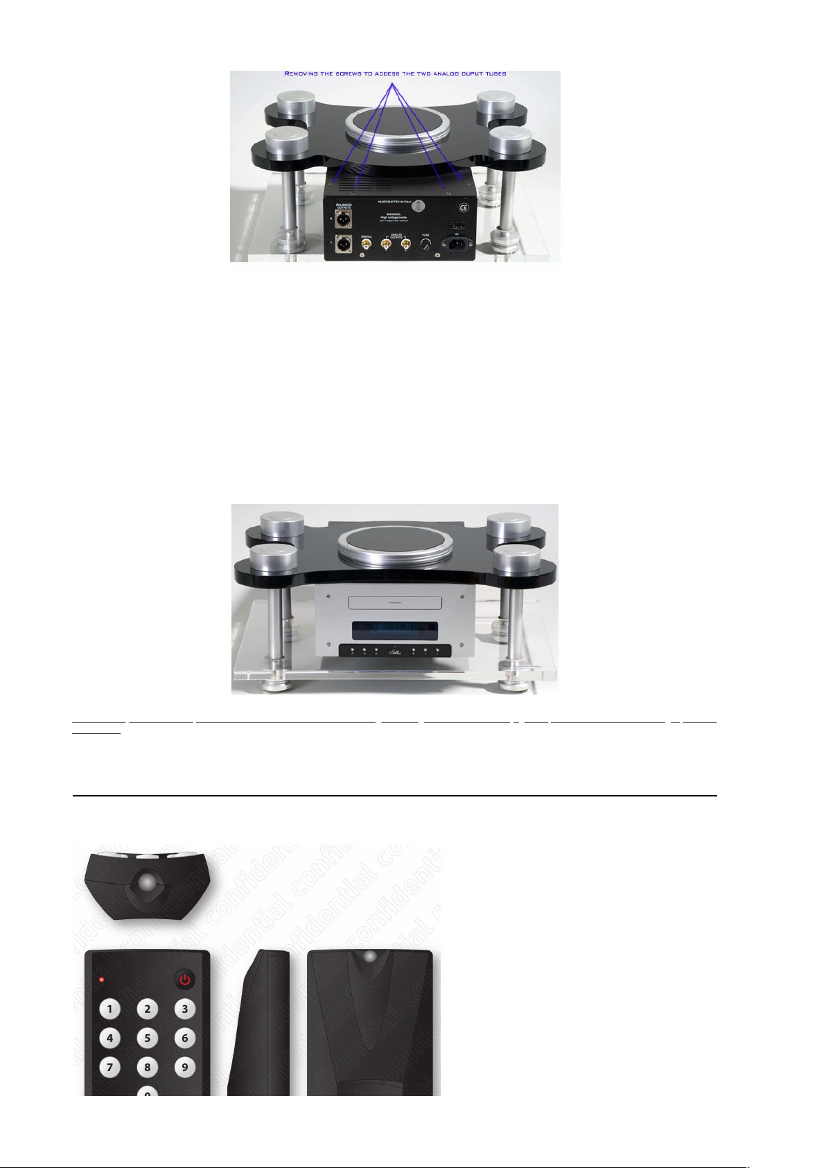
(REMOTE CONTROL)
The supplied remote handset can also control other Akamai sources to integrate with one handset eventually the control of all the Goldenote units.
 Loading...