

Page 1
INSTALLATION INSTRUCTIONS
Fixture Name: AUTUMN TWILIGHT 9903-BA1
For Wall Mount Light Fixture
WARNING! SHUT POWER OFF AT FUSE OR CIRCUIT BREAKER
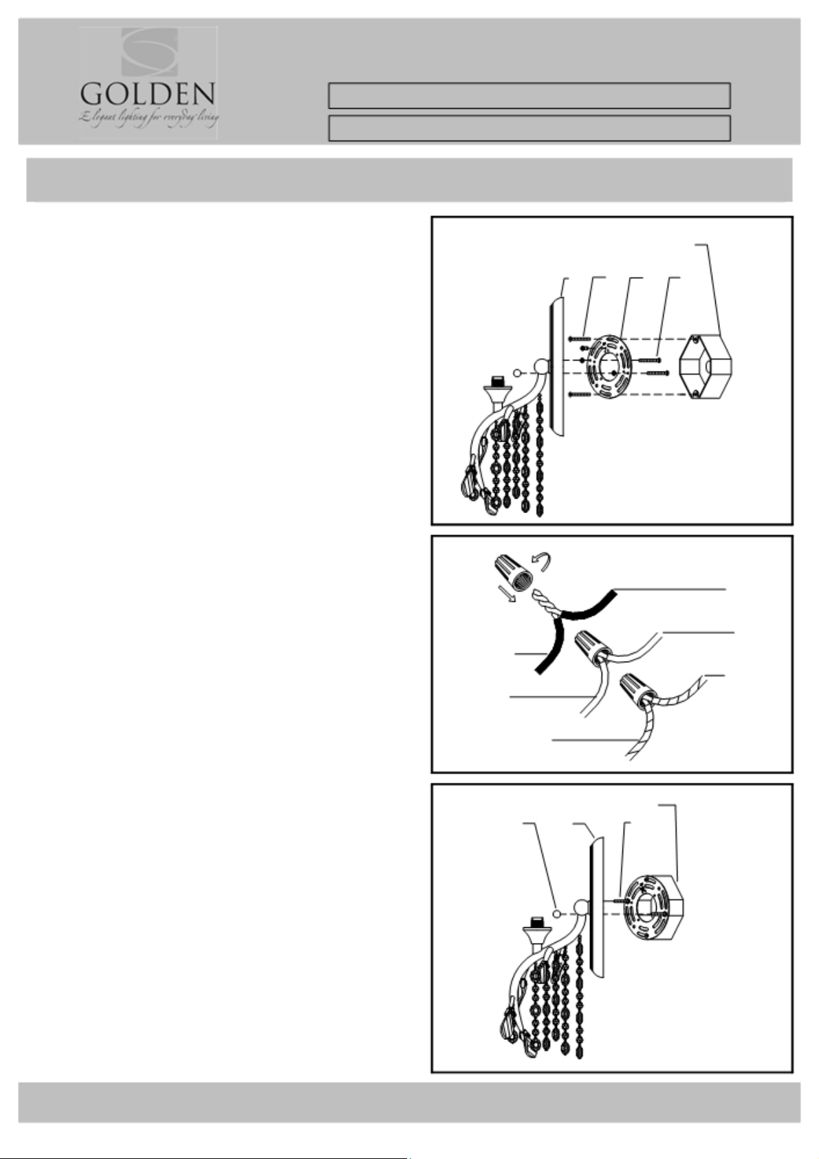
HANGING THE FIXTURE (Fig.1)
1.Carefully remove the new fixture from the carton
and the yellow parts bag. Check that all parts are
included as shown in th e illu str ation and Parts and
Assembly Sheet.
2. Shut off power at the circuit breaker and remove
the old fixtur e fr o m wal l, including the o ld
mounting str ap.
3. Mounting S tra p ( A) contains sev er a l pa irs o f
threaded holes. Fin d the pair of holes tha t matc hes
the spacing o f t he hole s in Back Plate (D) and
thread the two Mounting Screws (C) half way into
Mounting Strap (A).
4. Place Mounting Strap (A) over the Junction
Box so that Mounting Screws (C) are vertical or
horizontal, as requ i red by the fix tu re ty pe.
5. Atta ch Mo unting Strap ( A) to the Junction Box
using the t wo Mou n ti ng Screws (B). Tighten Mounting
Screws (B) securely with a screwdriver.
CONNECTING THE WIRES(Fig.2)
6. Attach the power supply wires to the fixture lead
wires by connecting BLACK to BLACK (or SMOOTH)
and WHITE to WHITE (or RIBBED).
7. Attach the GROUND wire (GREEN or COPPER)
from the Junc tio n Bo x an d the f ix tu re Gr o un d wir e
to the green G ro u nd S crew on the Mou n ting
Bracket (B) o r co nne c t bo th wires together u si ng
the correct size of wire connectors.
NOTE: Twist the wires together in the same direction
you twist the wire connector onto the wires .
8. Tuck these wir e co nnections ne a tly i n to the
Junction Box.
Fig.3
FINISHING THE INSTALLATION(Fig.3) E
9. After tucking the wire connect ions into
the Junction Bo x, p la ce B ack Plate
(D) over the two Mounting Screws (C) and secure
Back Plate (D ) against the wall by th re ad ing
two Deco Nuts (E) over Mounting Screws
(C) until tight (as shown on Fig. 3).
10. Install the crystals as per t he Pa rts and Assembly Sheet
instructions.
Fig. 1
Fig.2
FIXTURE WIRES
SMOOTH
(or Black)
RIBBED
(or White)
BARE COPPER
(or Green)
JUNCTION BOX
D B A
JUNCTION BOX
D C
C
HOUSE WIRES
BLACK
(Hot)
WHITE
(Neutral)
GREEN
(Ground)
YOUR INSTALLATION IS NOW COMPLETE. RETURN
POWER TO THE JUNCTION BOX AND TEST THE FIXTURE.
For Customer Service, contact the place of purchase to arrange for replacement parts.
CS A 0 5 5 3 0 1 WB L G 1
Page 2
PARTS & ASSEMBLY SHEET
Fixture Name: AUTU MN TWILIGHT 9903-BA1
This fixture assembled PO: Date:
Notice: Please review the parts listing and check for all parts before assembling the fixture. If any parts are missing or
damaged, please note on this sheet and contact the place of purchase to arrange for replacement parts.
Company Name:______________________Co Account#:__________
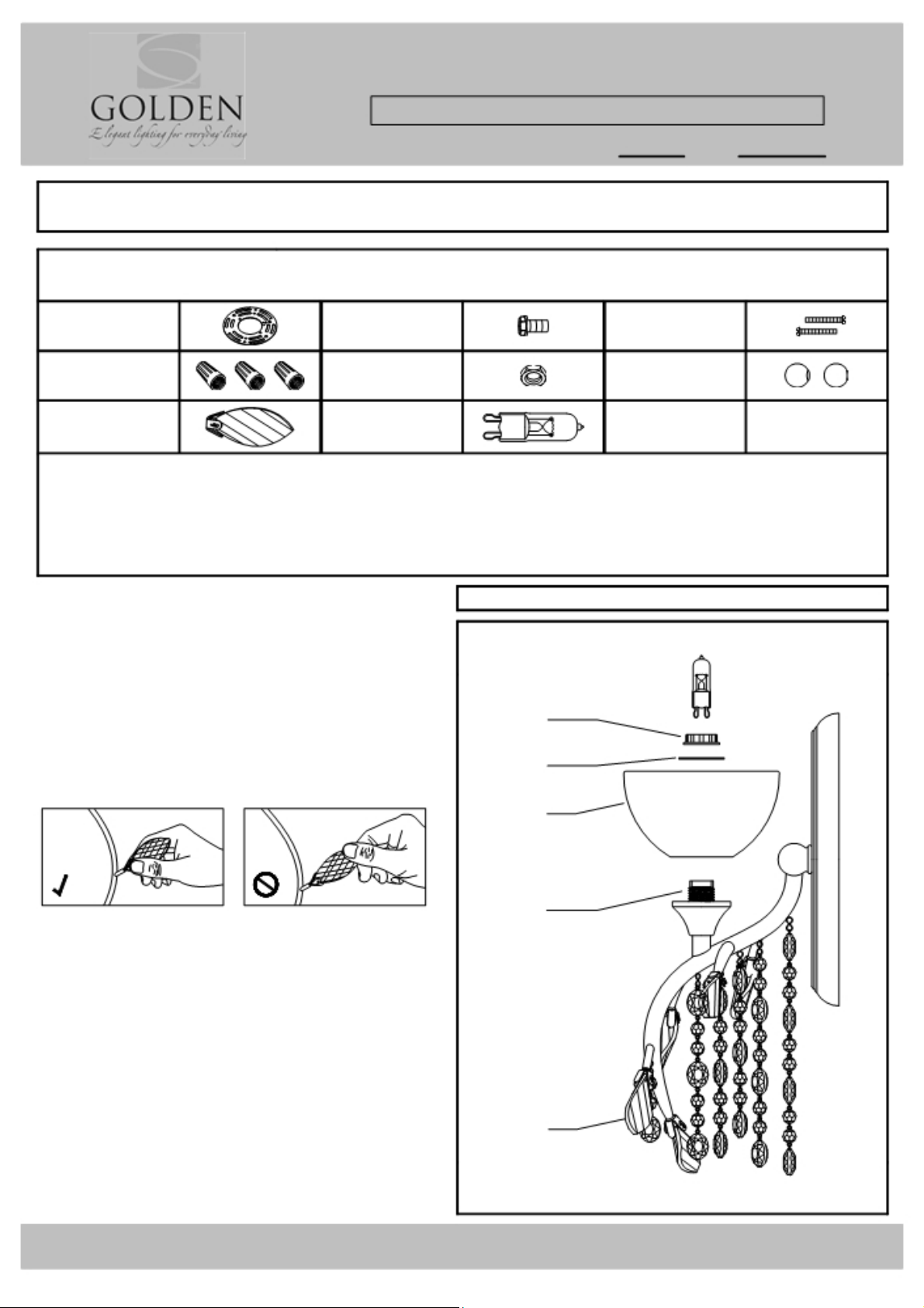
PARTS LIST
Mounting Strap Green Screw Mounting Screws
Φ102 ㎜ 1ea G8/32*H8 ㎜ 1ea H32 ㎜ 2ea H38 ㎜ 2ea
Wire Connectors Hex Nut Deco Nut
Orange 3ea G5/32*H4 ㎜ 2ea Φ12 ㎜ 2ea
below to be filled out by retailer
Crystal Leaf
PT-CRYSTAL-9903 LEAF
5ea W27*H65 ㎜
Bulbs
1ea Halogen,
Type G9 40W
Part Needed ______________________________ Quantity _________________________________
Part Needed ______________________________ Quantity _________________________________
Reason why (missing, scratched, broken glass, bent, bad fi nish)
Comments
FIXTURE ASSEMBLY INSTRUCTIONS
Read and review installation instruction sheet
Fig.1
9903-BA1
before assembling the fixt ure
1. Open the bag that is attac hed to t he fixtur e and
carefully arrange the bead strings.
2. Screw Crystal Lea f ( A) on the ar m.
Hold carefully by the metal base to prevent the
crystal from cra cking.
E
D
C
B
3. Place the Glass ( C) and P iece ( D ) over the S ocket
(B) and secure wit h S ock et R ing ( E) .
4. Install the light bulbs in accordance with the
fixture's specification.
Bulb note: Use a tissue or paper towel to hold the
bulb and push down into socket. Oils or dirt can
cause th e bu lb li fe to short en. Rubb i ng a lc oh o l is
recommended to clea n t he bu lbs i f dirt y .
(DO NOT EXCEED THE MAXIMUM WATTAGE RATING!)
A
NOTE: INSTALL THE GLASS ASSEMBLY
AFTER FIXTURE IS HUNG.
For Customer Service, contact the place of purchase to arrange for replacement parts.
CS A 0 5 5 3 0 1 WB L G 1
Page 3

 Loading...