

Page 1
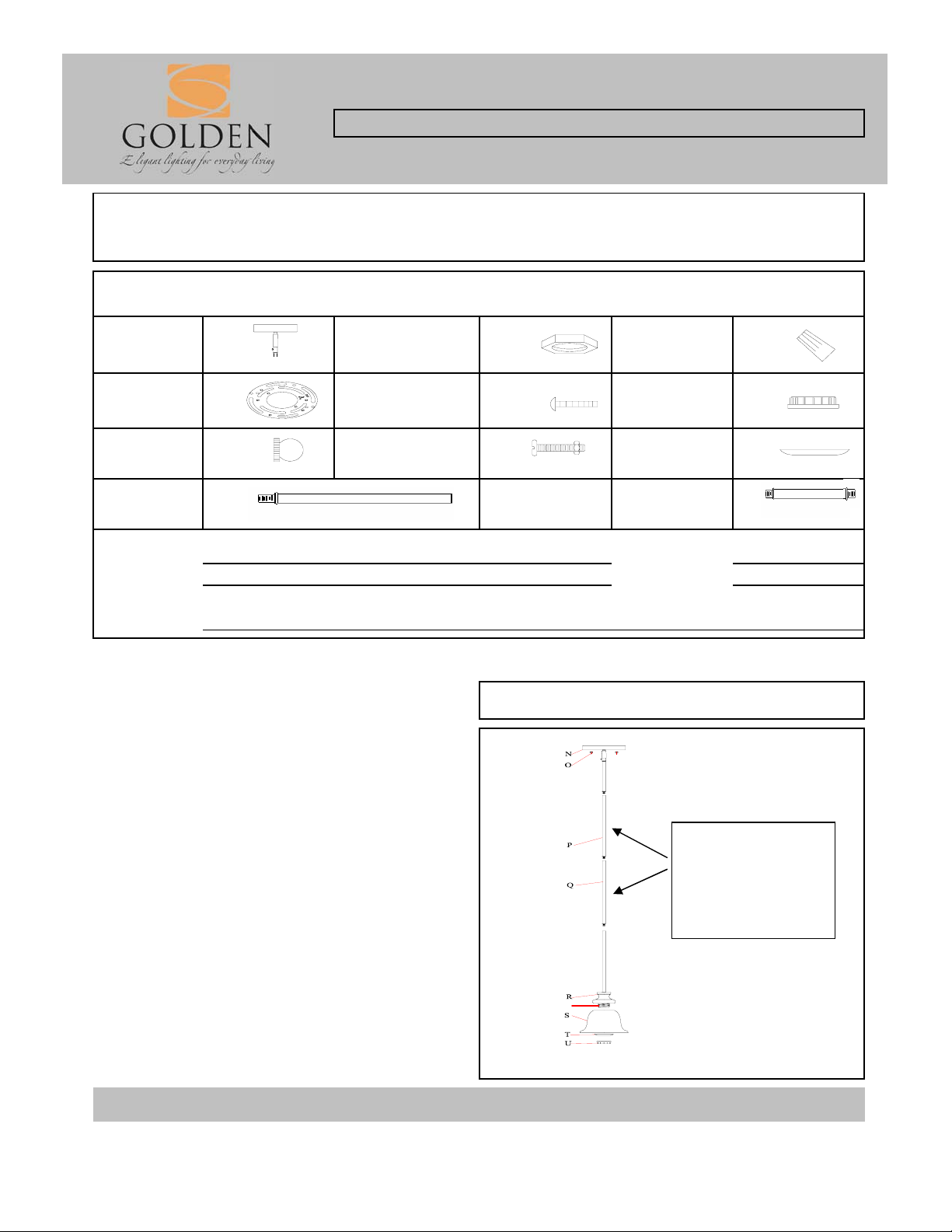
PARTS & ASSEMBLY SHEET
Fixture Name: Heartwood 8063-M1L BUS
This fixture assembled PO:__________ Date: ________
Notice: Please review the parts listing and check for all parts before assembling the fixture. If any parts
are missing or damaged, please note onthis sheet and contact the place of purchase to arrange for
replacement parts.
Company Name:_______________________Co. Account #:_____________
PARTS LIST
to be filled out by retailer
Canopy 1ea Hex nut 2ea
Mounting
bracket
Deco Nut
12" Rod
Part Needed Quantity
Part Needed Quantity
Reason why ( missing, scratched, broken glass, bent, bad finish)
Comments
1ea Mounting screws 2ea Socket rings
2ea
2ea 6" Rod
Fixture mounting
screws
2ea Socket washer 1ea
Wire
connectors
FIXTURE ASSEMBLY INSTRUCTIONS
Read and review installation instruction sheet, but
do not install before assembling the fixture.
1. By measuring determine correct number of rods
needed for proper hanging height. There are 2 optional
12" rods included.
2. To shorten the fixture trim the wires to the desired
length plus at least 8~10 inches.
2b. Slide the 6" rod plus the excess 12" rods off the wire.
2c. Thread the 6" rod back onto the wire then thread the
wire through the swivel conection into the canopy.
3. To lengthen the fixture pull all the wire out of the
canopy.
3b. Slide the 6" rod off the wire.
3c. Thread the additional rods with the 6" rod last back
onto the wire then thread the wire through the swivel
conection into the canopy.
Fig 1
8063-M1L BUS
These two Rods may
be removed
or
additional Rods may
be added.
ROD-12 BUS
2ea
1ea
1ea
NOTE: INSTALL THE GLASS ASSEMBLY
AFTER THE FIXTURE IS HUNG.
For Customer Service, contact the place of purchase to arrange for replacement parts.
Page 2
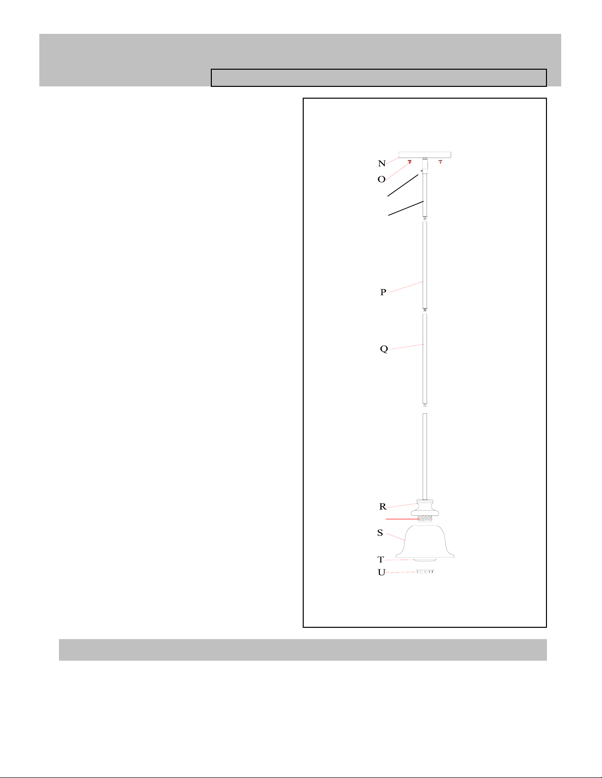
PARTS & ASSEMBLY SHEET
W
Fixture Name: Heartwood 8063-M1L BUS
4. Pull the fixture’s wire through the Rods until taut.
5. Thread Rod(Q)into Frame(R)until tight.
6. Thread Rod(P)into Rod(Q) until tight. repeat for
any additional rods.
7. Thread 6" Rod(W)into Rod(P)until tight.
8. Loosen the Set screw ( X ) just until the rod will fit in
the swivel coupler. Thread the 6" Rod(W)into the
canopy ( N ) and tighten the Set screw( X )
* You may now install the fixture.
X
9. Place the glass shade (S) over the threaded socket
(V) and place the Socket Washer (T) onto the threaded
socket (V) and secure both by threading the Socket ring
(U) until tight.
10. Install the light bulb in accordance with the fixture’s
specifications.
(DO NOT EXCEED MAXIMUM WATTAGE RATING!)
Fig 2
V
For Customer Service, contact the place of purchase to arrange for replacement parts.
Page 3

INSTALLATION INSTRUCTIONS
Fixture Name: Heartwood 8063-M1L BUS
For Mini Pendant Light Fixture
WARNING ! SHUT OFF POWER AT FUSE OR CIRCUIT BREAKER.
HANGING THE FIXTURE as Semi flush (Fig. 1)
1. Carefully remove the new fixture from the carton and
the yellow bag that holds all your parts. Check that all
parts are included as shown in the illustration and parts
list.
2. Shut off power at the circuit breaker and remove the old
fixture from ceiling, including the old mounting strap.
3. The Mounting bracket ( C ) contains several pairs of
threaded holes, find the pair of holes that match the hole
spacing in your fixture Back Plate (N) and thread the two
Mounting Screws (B) half way into the Mounting Strap (C)
facing down, these will have their threaded ends protrude
through the two holes in the fixture canopy(N).
4. Place the Mounting Strap ( C ) over the junction box
5. Attach the Mounting Strap (C) to the Junction Box using
the two mounting screws (E). Tighten the screws (E)
securely with screw driver.
CONNECTING THE WIRES (Fig 2)
6. Attach the power supply wires to the fixture lead wires
by connecting BLACK to BLACK (or SMOOTH) and
WHITE to WHITE (or RIBBED).
7. Attach the GROUND wire(GREEN or COPPER) from
the Junction Box and the fixture Ground wire to the green
Ground Screw (F) on the Mounting Bracket (C) or
connect both wires together using the correct size of wire
connectors. -
NOTE:Twist the wires together in the same direction you
twist the wire connector onto the wires.
8. Tuck these wire connections neatly into the Junction
Box.
Fig. 1
N
Fig. 2
FINISHING THE INSALLATION (Fig.3)
9. Place the fixture’s canopy over the Mounting Bracket
(C) and over the Mounting Screws (B), adjust the fixture
canopy (N) until the Mounting Screws (B) protrude out
from the canopy (N) and secure the fixture against the
ceiling by threading the decorative nuts(O) until tight.
10. Install the light bulbs and glass shade as per the
fixture assembly sheet.
YOUR INSTALLATION IS NOW COMPLETE. RETURN
POWER TO THE JUNCTION BOX AND TEST THE
FIXTURE.
Fig. 3
For Customer Service, contact the place of purchase to arrange for replacement parts.
 Loading...