

Page 1
*Insert the Deco screw (24) through the hole, hold glass up to the installed backplate(15) and secure by threading the
Company Name:_______________________Co. Account #:_____________
PARTS & ASSEMBLY SHEET
Fixture Name: Mayfair 7116-WSC LC
This fixture assembled PO:__________ Date: ________
Notice: Please review the parts listing and check for all parts before assembling the fixture. If any parts are missing
or damaged, please note onthis sheet and contact the place of purchase to arrange for replacement parts.
PARTS LIST
Mounting Strap Mounting Screws Metal Cap Nut
1ea 4-1/8-IP*H2mm 2ea 8#32-IP*1" 1ea 1/8-27-IP*H15mm
Wire connectors Nipple Hex Nut
3ea P3 Orange 1ea 1/8-27-IP*1-3/4"
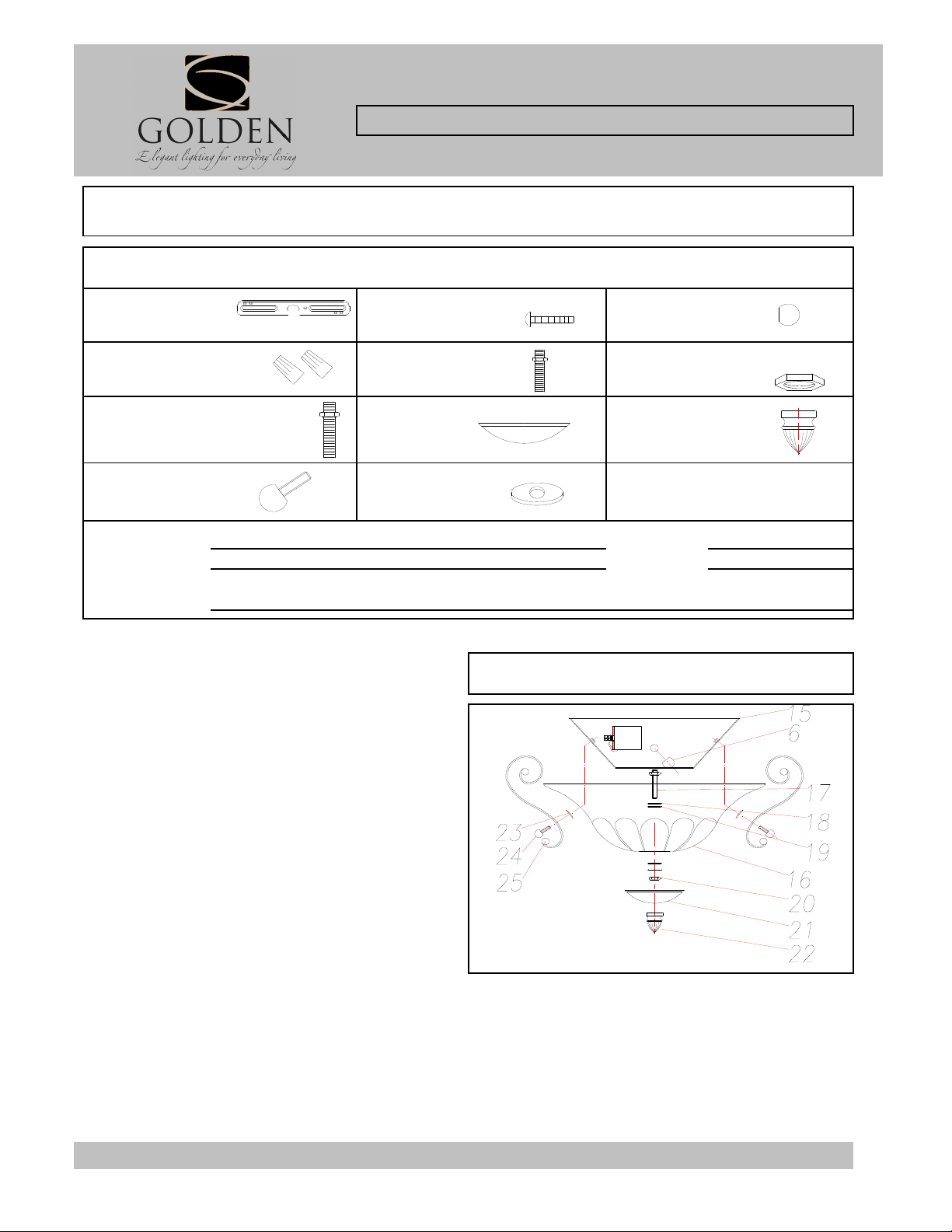
Nipple (17) Finial
1ea 1/8-27-IP*2-1/8"
*may have washers, hex nuts attached
Deco Screw
2ea 5/32-IP*9MM 2ea ∅14mm
Part Needed Quantity
Part Needed Quantity
Reason why ( missing, scratched, broken glass, bent, bad finish)
Comments
F
IXTURE ASSEMBLY INSTRUCTIONS
Read and review installation instruction sheet, but do
not install before assembling the fixture.
to be filled out by retailer
Bottom Cap
1ea ∅3-1/4"*H1-3/4"
Rubber Washer
Fig 1
3ea 1/8-27-IP*H3mm
1ea 1/8-27-IP*H30mm
7116-WSC LC
1. Thread on the nipple (17) in this order: hex nut, metal
washer (18), plastic washer (19), glass shade (16) thread
the nipple through the hole in bottom of glass shade,
plastic washer, metal washer, hexnut (20) , bottom cap
(21) and secure in place with the Finial (22).
2. Install the light bulb in accordance with the fixture's
specifications.
(DO NOT EXCEED MAXIMUM WATTAGE RATING
3. Unscrew the Deco screws (24) and Rubber washers (23) from fixture backplate.
*Place the scroll arm (25) against the side of Glass shade (16) with the small rubber washer between the arm and
glass.
Deco screw (24) into the side of backplate.
*Continue to hold glass and repeat with the other side.
NOTE: I
NSTALL THE GLASS ASSEMBLY AFTER THE FIXTURE IS HUNG.
For Customer Service, contact the place of purchase to arrange for replacement parts.
7116-PartsInstallation_20110106m.xls
Page 2
(D) and continue turning until the Back Plate (15) is snug
INSTALLATION INSTRUCTIONS
G
F
D
E
Fixture Name: Mayfair 7116-WSC LC
For Wall Mount Light Fixture
WARNING ! SHUT OFF POWER AT FUSE OR CIRCUIT BREAKER.
HANGING THE FIXTURE (Fig. 1)
1. Carefully remove the new fixture from the carton and
the yellow bag that holes all your parts. Check that all
parts are included as shown in the illustration and parts
list.
2. Shut off power at the circuit breaker and remove the
old fixture from wall, including the old mounting strap.
3. Take Threaded Rod (D) from parts bag and thread
into center screw hole on Mounting Strap (A), tighten
with Hex Nut (B) and Spring Washer (C).
4. Attach the Mounting Strap (A) to the Junction Box (I)
using the two Mounting Screws (E). Tighten the screws
securely.
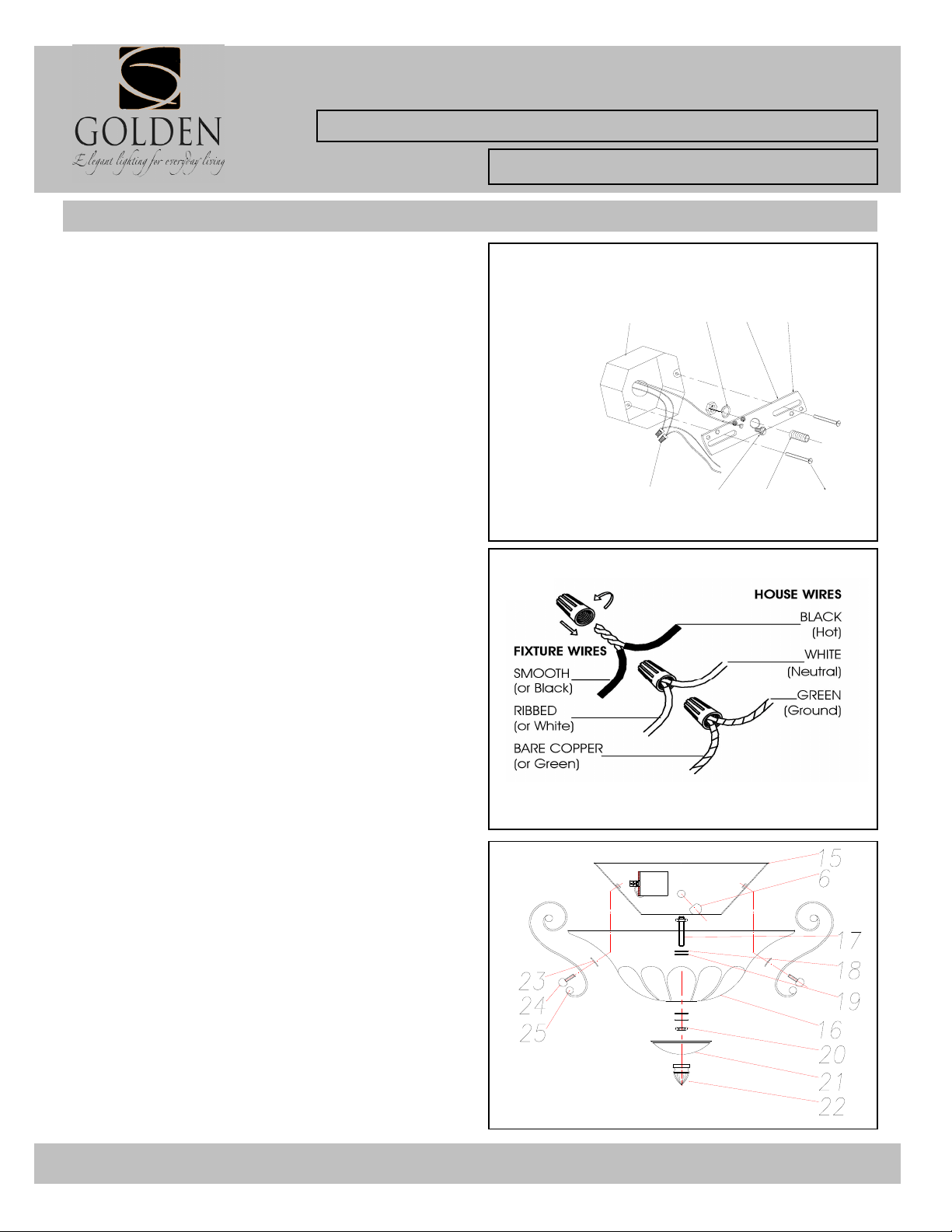
CONNECTING THE WIRES (Fig. 2)
5. Attach the power supply wires to the fixture lead wires
by connecting BLACK to BLACK (or SMOOTH) and
WHITE to WHITE (or RIBBED).
6. Attach the GROUND wire(GREEN or COPPER) from
the Junction Box and the fixture Ground wire to the
green Ground Screw on the Mounting Bracket (A) or
connect both wires together using the correct size of
wire connectors.
NOTE:Twist the wires together in the same direction you
twist the wire connector onto the wires.
7. Tuck these wire connections neatly into the Junction
Box.
Fig. 1
Fig. 2
JUNCTION BOX
A
B
I
C
D
N
G
FINISHING THE INSTALLATION (Fig. 3)
8. Place the fixture Back Plate (15) over the Threaded
Rod (D), so it protrudes through the hole in the Back
Plate (15).
9. Thread the Metal Cap Nut (6) onto the Threaded Rod
against the wall.
10. Install glass as per the fixture assembly instructions.
YOUR INSTALLATION IS NOW COMPLETE. RETURN
POWER TO THE JUNCTION BOX AND TEST THE
FIXTURE.
For Customer Service, contact the place of purchase to arrange for replacement parts.
Fig. 3
 Loading...