

Page 1
Canopy Wire connectors Top loop
1ea 5" X 1" 2ea P3 Orange 1ea 3/8 x 66mm
Chain
Junction Box
Screw
1ea 6ft x 3.8mm 2ea 8/32" x 1"
Chain connector Nipple
2ea 4 X 55mm 1ea 3/8 x 30mm x 5mm 1ea 3/8 x 45mm
Mounting Strap
w/ ground screw
Hex Nut Spring Washer
1ea 3/4" X 4"
2ea 3/8 x 3mm 1ea 15 x 3mm
Bottom cap
Flat washer Finial
1ea 99 x 34mm
1ea 1" x 3mm 1ea 3/8 x 40mm
Part Needed Quantity
Part Needed Quantity
Reason why (missing, scratched, broken glass, bent, bad finish)
Comments
Fig. 1
NOTE: INSTALL THE GLASS ASSEMBLY AFTER THE
FIXTURE IS HUNG.
PARTS & ASSEMBLY SHEET
6005-3P
Read and review installation instruction sheet before
assembling the fixture.
FIXTURE ASSEMBLY INSTRUCTIONS
This fixture assembled PO:__________ Date: ________
Fixture Name: Lancaster 6005-3P PW/RBZ/AB
Canopy Loop
with Collar
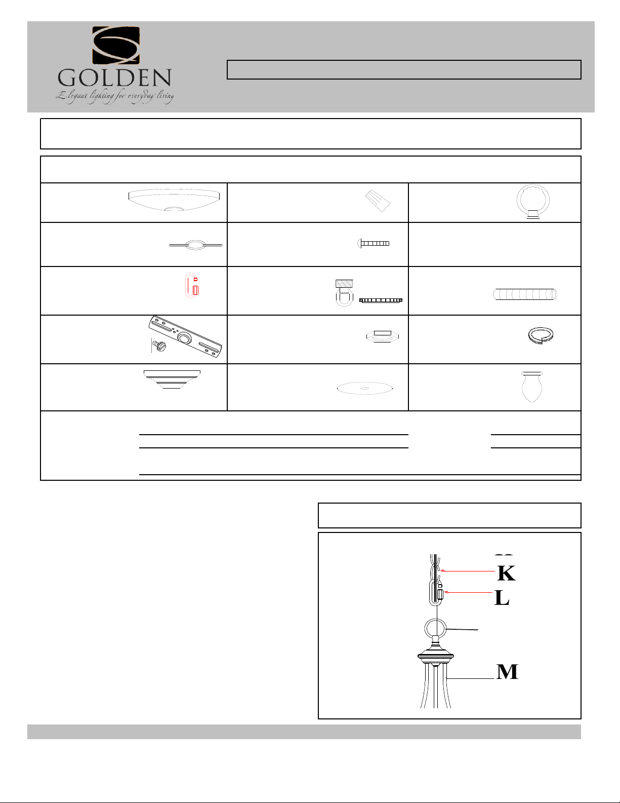
ASSEMBLING THE FIXTURE (Fig. 1)
1. Feed the fixture wires through the Top Loop (J) and pull
the wires until taut.
2. Then screw the Top Loop (J) to the threaded center
column of Frame (M) until tight.
3. Gently spread the arms until evenly spaced if arms are
packed closed.
Notice: Please review the parts listing and check for all parts before assembling the fixture. If any parts are missing or
damaged, please note on this sheet and contact the place of purchase to arrange for replacement parts.
PARTS LIST
Company Name:_______________________Co. Account #:_____________
to be filled out by retailer
For Customer Service, contact the place of purchase to arrange for replacement parts.
D
C
J
6005-3PPartsInstallation_111004m.xls
Page 2
For Customer Service, contact the place of purchase to arrange for replacement parts.
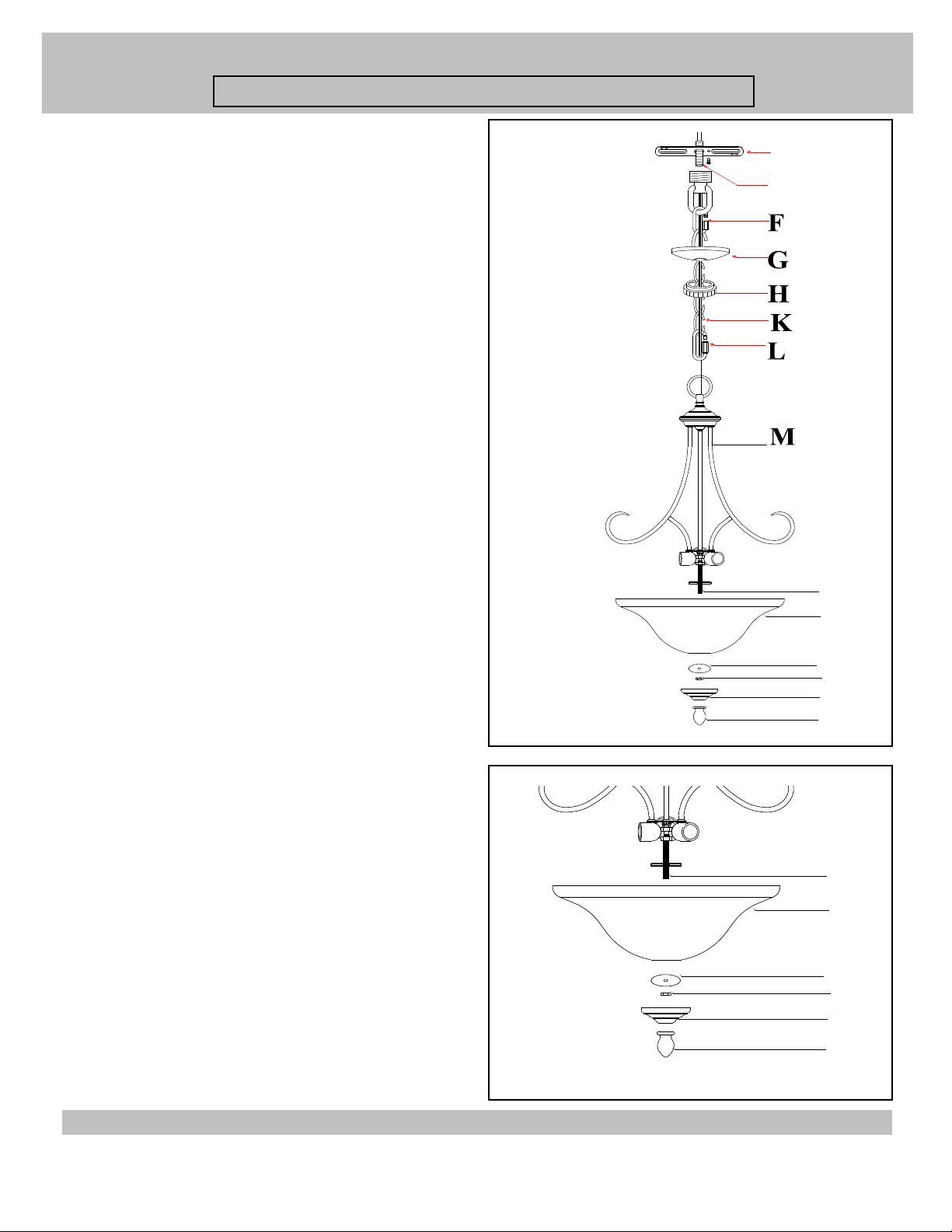
7. Slip Canopy loop collar (H) over the chain, then do the
same with the canopy (G).
8. When ready to complete the installation, use the remaining
chain connector to attach the loose end of the chain to the
canopy loop (F). Close the chain connector.
9. Make sure the weight of the chandelier will be supported
by the chain - not the electrical wire.
* You may now install the fixture.
4. By measuring determine correct number of links needed
for proper hanging height. Use a pair of pliers to open one
link of the Chain (K) then remove the excess Chain (K) and
discard it.
5. Use one chain connector (L) to attach one end of the chain
to the Top Loop (J) and close the chain connector.
6. Feed the fixture wires through the Chain (every three links)
and pull the wires until taut.
Fig 2
Note: Complete these remaining steps after the fixture is
hung.
10. Thread the threaded rod/nipple (N) onto the socket
assembly coupler, and secure with a hex nut.
11. Install the light bulbs in accordance with the fixture's
specifications.
12. Slide the Glass shade (O) and Flat washer (P) over the
Nipple (N), and secure in place with the Hex nut (Q). Slide
the Bottom Cap (R) over the Nipple (N), and secure in place
with the Finial (S).
(DO NOT EXCEED MAXIMUM WATTAGE RATING)
Fig 3
PARTS & ASSEMBLY SHEET
Fixture Name: Lancaster 6005-3P PW/RBZ/AB
D
C
D
C
S
N
O
P
Q
R
D
C
S
N
O
P
Q
R
6005-3PPartsInstallation_111004m.xls
Page 3

For Chandelier Light Fixture
INSTALLATION INSTRUCTIONS
WARNING ! SHUT OFF POWER AT FUSE OR CIRCUIT BREAKER.
Fixture Name: Lancaster 6005-3P PW/RBZ/AB
For Customer Service, contact the place of purchase to arrange for replacement parts.
HANGING THE FIXTURE (Fig. 1)
1. Carefully remove the new fixture from the carton and the yellow bag that
holds all parts. Check that all parts are included as shown in the illustration and
parts list.
2. Shut off the power at the circuit breaker and remove the old fixture from
ceiling, including the old mounting strap.
3. Thread Nipple (C) into Canopy Loop (F) until snug.
4. Thread other end of the Nipple (C) with Canopy Loop attached into Mounting
Strap (D).
5. Place Lock Washer (B) over end of Nipple (C) protruding through Mounting
Strap (D) and thread Hex Nuts (A) onto Nipple until tight.
6. Take this mounting strap assembly and mount to ceiling junction box with
junction box Screws (E). Tighten screws securely with screwdriver.
CONNECTING THE WIRES (Fig. 2)
10. Attach the power supply wires to the fixture lead wires by connecting
BLACK to BLACK (or SMOOTH) and WHITE to WHITE (or RIBBED).
NOTE: Twist the wires together in the same direction you twist the wire
connector onto the wire
11. Attach the GROUND wire (GREEN or COPPER) from the junction box and
the fixture ground wire to the green ground screw on the Mounting Bracket (D).
Or connect both wires together using a wire connector.
12. Tuck these wire connections neatly into the Junction Box.
13. Raise Canopy (G) to the ceiling and secure in place by tightening the
Canopy Loop Collar (H) into the Canopy Loop (F).
14. Install the light bulbs and glass shade according to the fixture assembly
sheet.
Fig. 2
YOUR INSTALLATION IS NOW COMPLETE.
RETURN POWER TO THE JUNCTION BOX
AND TEST THE FIXTURE.
Fig. 1
7. Unscrew the Canopy loop collar (H) from the Canopy loop. Take the canopy
and pass over the Canopy loop. Approximatly half of the canopy loop exterior
threads should be exposed. Adjust until desired height is reached. *the Canopy
loop collar should fit snugly on the Canopy loop after the canopy is installed.
Remove Canopy and Canopy lock collar.
8. Assemble the fixture and have an assistant support the weight of the fixture
while you complete the wiring connections.
9. Thread the fixture wires and ground wire of the assembled fixture through the
canopy loop and nipple and into the outlet box.
L
B
C
A
JUNCTION BOX
(CEILING)
D
E
F
H
J
CHAIN
G
BARE COPPER
(Ground)
GREEN
(Ground)
FIXTURE WIRES
SMOOTH (BLACK)
RIBBED (WHITE)
BLACK
WHITE
HOUSE WIRES
 Loading...