

Page 1
For Customer Service, contact the place of purchase to arrange for replacement parts.
INSTALLATION INSTRUCTIONS
Fixture Name: BEAU JARDIN 5400-9 RG
For Pendant Light Fixture
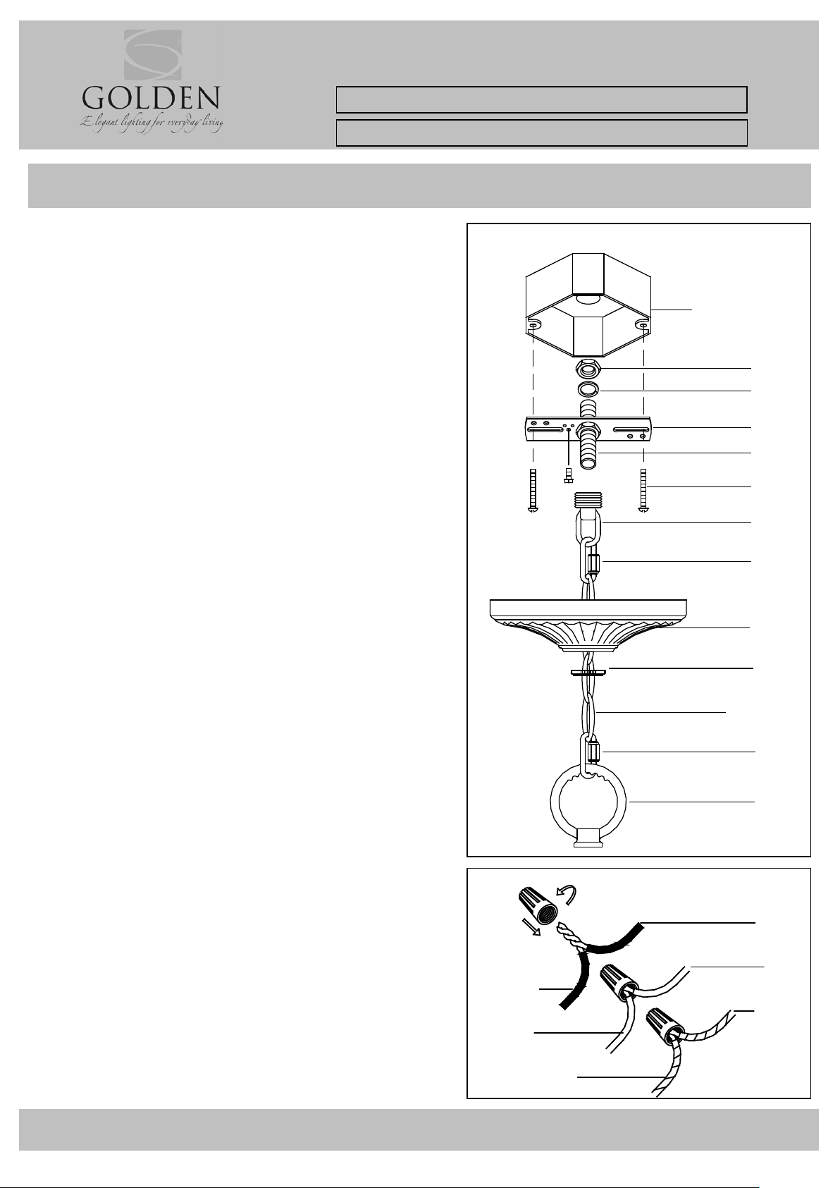
HANGING THE FIXTURE (Fig.1)
1. Carefully r emo ve the ne w fixt ure from the car ton and the
Fig.2
FIXTURE WIRES
(or Green)
HOUSE WIRES
(Neutral)
GREEN
(Ground)
JUN C TIO N BOX
(CEILING)
A
B
D
C
E
F
I
I
G
H
CHAIN
J
WARNING! SHUT POWER OFF AT FUSE OR CIRCUIT BREAKER
yellow bag that holds all p a rts. Check tha t all parts are
included as shown in the illustratio n a nd parts list.
2. Shut off the power at the c ircuit breaker and re move old
fixture fro m c e iling, including the old mounting strap.
3. Thread Nipple(C) int o Ca nopy Loop (F) until snug .
4. Thread othe r end of the Nipple (C) wit h Canopy Lo op
attached int o Mounting Strap (D).
5. Place Lock Washer (B) over end of Nip ple (C) protruding
through Mou nting Strap (D) and thread Hex Nuts (A) onto
Nipple unti l tight.
6. Take this mounting strap assembly a nd mount t o c e iling
junction box with junction box Screws (E). Tighten screw
securely with screw driver.
7. Unscrew t he Canopy loop collar (H) from the Cano py
loop. Take t he c anopy and pa ss over the Canopy loop.
Approximately one half of the ca nopy loop exterior
threads should be exposed. Adjust until desired height is
reached. *the Canopy loop c ollar should f it snugly on the
Canopy loop after the canopy is inst alled. Remove
Canopy and Canopy loop collar.
8. Assemble the fixture and have an assistant or secure
support hold the weight of the fixture while you complete
the wiring connections.
9. Thread the fixture wir es and ground wire of the
assembled fixture through the canopy loop (F) and
nipple(C) and chain (every three links) into t he out let box .
CONNECTING THE WIRES (Fig.2)
10. Attach the power supply wires to the fixture lead wires
by connectin g BLACK to BLACK (or SMOO TH) and WHITE
to WHITE (or RIBBED).
11. Attach the GROUND wire (GREEN or COPPER) from the
Junction Box and the fixture Ground w ire to the gre en
Ground Screw on the Mounting Bracket (B) or con nect
both wires together using the corre c t size of wire
connectors.
NOTE: Twist the wires together in the same direction you
twist the wire connector onto the wires.
12. Tuck thes e wire connections neatly into the Junction
Box.
FINISHING THE INSTALLATION (Fig.3)
13. Raise Canopy (G) to the ceiling and secure in place by
tightening the Canopy loop collar (H) into the Canopy
Loop (F).
14. Install the light bulbs and glass shade as per t he fixture
YOUR INSTALLATION IS NOW COMPLETE. TURN POWER ON AT
TO THE JUNCTION BOX & TEST THE FIXTURE.
assembly sheet.
Fig.1
SMOOTH
(or Black)
RIBBED
(or White)
BARE COPPER
BLACK
(Hot)
WHITE
CSA054009HBLG1.DOC
Page 2
C
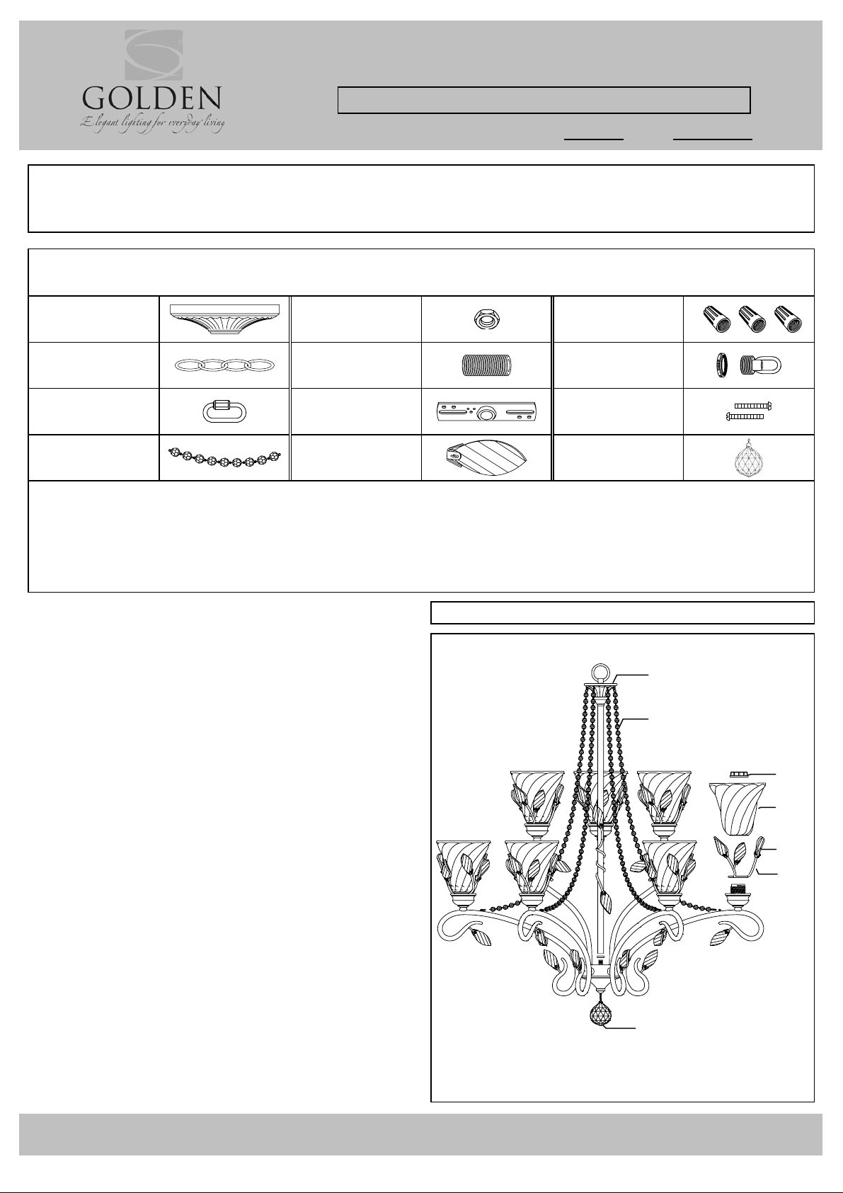
PARTS & ASSEMBLY SHEET
Fixture Name: BEAU JARDIN 5400-9 RG
This fixture assembled PO: Date:
Notice: Please review the parts listing and check for all parts before assembling the fixture. If
any parts are missing or damaged, please note on this sheet and contact the place of
purchase to arrange for replacement parts.
Company Name:______________________Co Account#:__________
PARTS LIST
below to be filled out by retailer
Canopy
1ea Φ160*H42 ㎜
Chain
1ea Φ5.0*6ft
Link
2ea W20*H45 ㎜
Bead String
6ea L720 ㎜
Hex Nut
2ea NPS-1/4-18
Nipple
1ea NPS 1/4-18*65
Mounting Strap
1ea W103*T2.0 ㎜
Crystal Leaf
71ea W27*H65 ㎜
㎜
Wire Connectors
3ea Orange
Canopy Loop
1ea NPS 1/4-18*H41
Mounting Screws
2ea G8/32*H32 ㎜
Crystal Drop
1ea W58*H65 ㎜
㎜
Part Needed ______________________________ Quantity _________________________________
Part Needed ______________________________ Quantity _________________________________
Reason why (missing, scratched, broken glass, bent, bad finish)
Comments __________________________________________________________________________
FIXTURE ASSEMBLY INSTRUCTIONS
Read and review installation instruction sheet
before assembling the fixture
5400-9 RG
Fig.3
A
1. Screw Column (A) on the nipple until tight.
2. Screw Crystals (B) on the fixture body and
D
Outside Shade Ring (C)”OSRING”.
3. Hook the draping Bead String (D) and
Crystal Drop (E) on the body
4. Place OSRING (C) and Glass Shade (F) over
the socket and secure with Socket Ring (G).
5. Install the bulbs as specified.
(no bulbs included in the package)
(Do not exceed the maximum wattage rating!)
G
F
B
E
For Customer Service, contact the place of purchase to arrange for replacement parts.
CSA054009HBLG2
 Loading...