

Page 1
Reason why ( missing, scratched, broken glass, bent, bad finish)
Comments
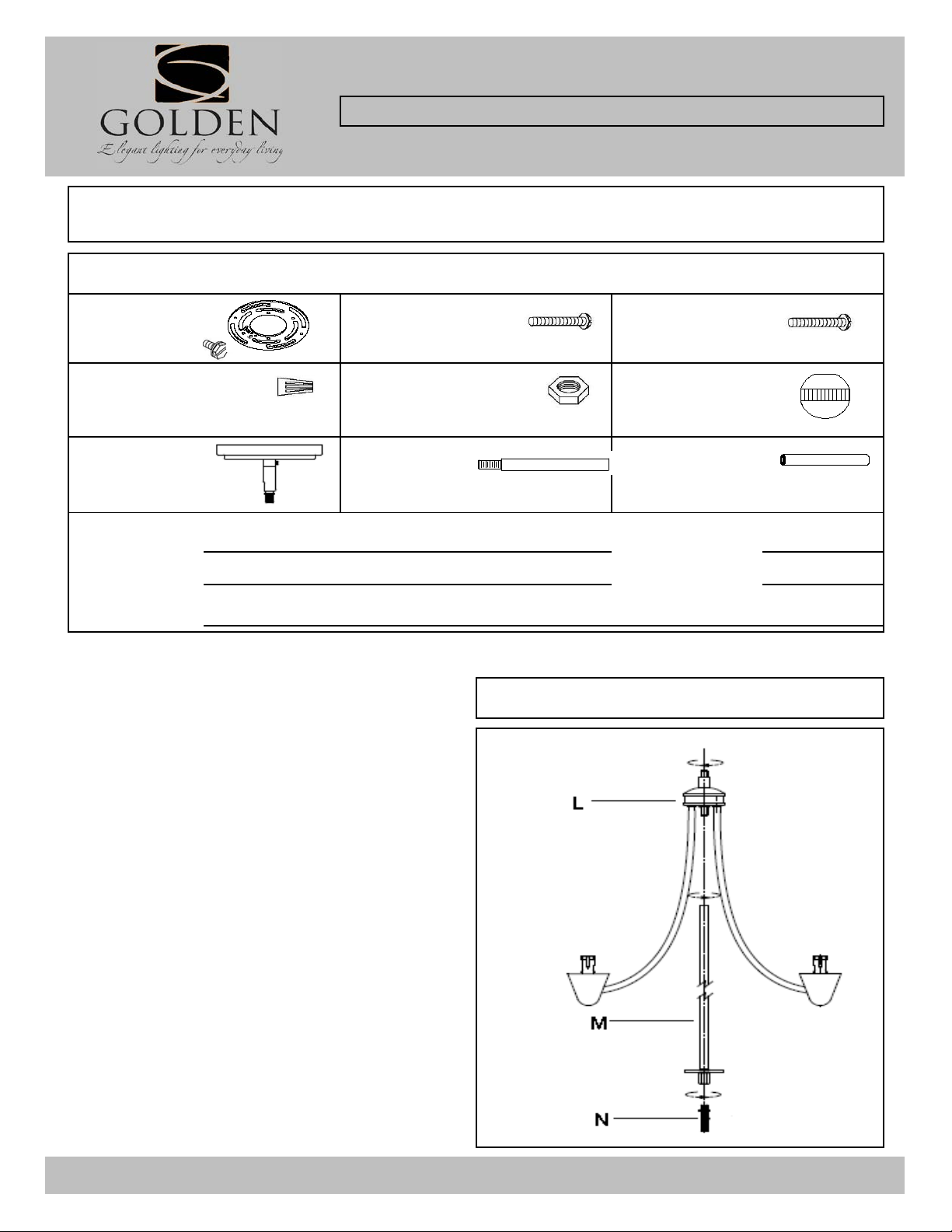
PARTS & ASSEMBLY SHEET
Please review the parts listing and check for all parts before assembling the fixture. If any parts are missing or
Company Name:_______________________Co. Account #:_____________
below to be filled out by retailer
Read and review installation instruction sheet before
NOTE: I
Fixture Name: Ol ympia 1648-M3 BUS
This fixture assembled PO:__________ Date: ________
Notice:
damaged, please note on this sheet and contact the place of purchase to arrange for replacement parts.
PARTS LIST
Mounting strap Mounting Screw Mounting screw
1ea 4" 2ea 8/32"X28mm 2ea 8/32X1"
Wire connnector Hex Nut
3ea P4 Orange 2ea 8/32"X3.5mm 2ea @12mm
Canopy Rod Rod
1ea 130 Dia*H70mm 3ea 12.7mmD ia* H12“ 1ea 12.7mmDia* H6”
Deco nut
nut)
(round
Part Needed Quantity
Part Needed Quantity
IXTURE ASSEMBLY INSTRUCTIONS
F
assembling the fixture.
Fig. 1
1. Unfold the arms of the fixture body to proper locations.
2. Thread the Center column (M) onto the protruding
nipple at bottom center of the fixture Top cap (L).
3. Thread the nipple (N) into the bottom coupler of Center
column (M).
1648-M3 BUS
NSTALL THE GLASS ASSEMBLY
AFTER THE FIXTURE IS HUNG.
For Customer Service, contact the place of purchase to arrange for replacement parts.
Page 2
PARTS & ASSEMBLY SHEET
Fixture Name: Olympia 1648-M3 BUS
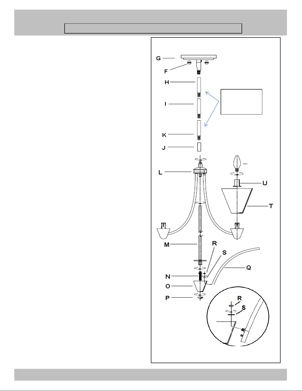
ASSEMBLING THE FIXTURE (Fig. 2)
4. Locate the nipple and pin on the bottom end of
the arm (Q) through the mounting holes on the side
of the Bottom cap (O).
Secure with hex nut (R) and lock washer (S).
Tighten until snug with pliers. Repeat with remaining
arms.
5. Place the combination of t he Bottom cap (O) with
arms (Q) over the nipple (N), aligning t he arm loops
around the top arms. secure in place with the finial
(P).
6. By measuring determine correct number of rods
needed for proper hanging height.
* This fixture includes 4 rods (6", 12", 12", 12")
7. To shorten the fixture; slide the excess rods off
the wires. To lengthen add additional rods.
8. Pull the fixture’s wires thr ough the rods (H,I,J,K)
until taut and thread the rods together. Then thread
to the fixture coupler at t op of fixtur e body (L) and
the swivel joint on canopy (G).
* You may now install the fixture.
Note: Complete these remaining steps after the
fixture is hung.
9. Slide the glass shade ( T) and candle sleeves (U)
over the socket of fixture body (L).
10. Install the light bulbs in accordance with the
fixture's specification.
(DO NOT EXCEED THE MAXIMUM WATTAGE)
Fig. 2
These three
rods may be
removed.
Bulb
(Not
provided)
For Customer Service, contact the place of purchase to arrange for replacement parts.
Page 3

INSTALLATION INSTRUCTIONS
BARE COPPER
(Ground)
GREEN
(Ground)
FIXTURE WIRES
SMOOTH (BLACK)
RIBBED (WHITE)
BLACK
WHITE
HOUSE WIRES
Fixture Name: Olympia 1648-5/9/M3/M1L BUS
For Pendant Light Fixture
WARNING ! SHUT OFF POWER AT FUSE OR CIRCUIT BREAKER.
HANGING THE FIXTURE (Fig. 1)
1. Carefully remove the new fixtur e from the carton and t he
yellow bag that holes all your parts. Check that all parts ar e
included as shown in the illustration and parts list.
2. Shut off power at the circuit br eaker and remove the old
fixture from wall, including the old mounting strap.
3. The Mounting Strap (A) cont ains several pairs of threaded
holes, find the pair of holes that match the holes spacing in
your fixture Canopy (G) and thread the two Mounting Screws
(B) into the Mounting Strap (A). Secure with Hex nuts (C).
These will have their threaded ends protrude through the two
holes in the fixture canopy.
4. Place the Mounting Strap ( A) over the Junction Box (E) so
the Mounting Screws (B) are vertical or horizontal, as required
by fixture type.
5. Attach the Mounting Strap (A) to the Junction Box (E) by
using the two Mounting scr ew s ( D) . Tighten the screws securly.
CONNECTING THE WIRES (Fig. 2)
5. Attach the power supply wires to the fixture lead wires by
connecting BLACK to BLACK (or SMOOTH) and WHITE to
WHITE (or RIBBED).
6. Attach the GROUND wire(GREEN or COPPER) from the
Junction Box and the fixture Ground wire to the green Ground
Screw on the Mounting Bracket (A) or connect both wires
together using the correct size of wire connectors.
NOTE: Twist the wires together in the same direction you twist
the wire connector onto the w ir es.
7. Tuck these wire connections neatly into the Junction Box.
FINISHING THE INSTALLATION (Fig. 3)
9. Place the fixture Canopy ( G ) , over the Mounting screws (B),
so they protrude through the holes in the Canopy (G) .
10. Thread the Deco Nuts ( F) ont o t he M ount ing Screws (B)
and continue turning until the Canopy (G) is snug against the
ceiling.
11. Install glass shades as per the fixture assembly
instructions.
YOUR INSTALLATION IS NOW COMPLETE.
RETURN POWER TO THE JUNCTIO N BOX AND TEST THE
FIXTURE.
Fig. 1
Fig. 2
Fig. 3
For Customer Service, contact the place of purchase to arrange for replacement parts.
 Loading...