

Page 1
Read and review installation instruction sheet, but
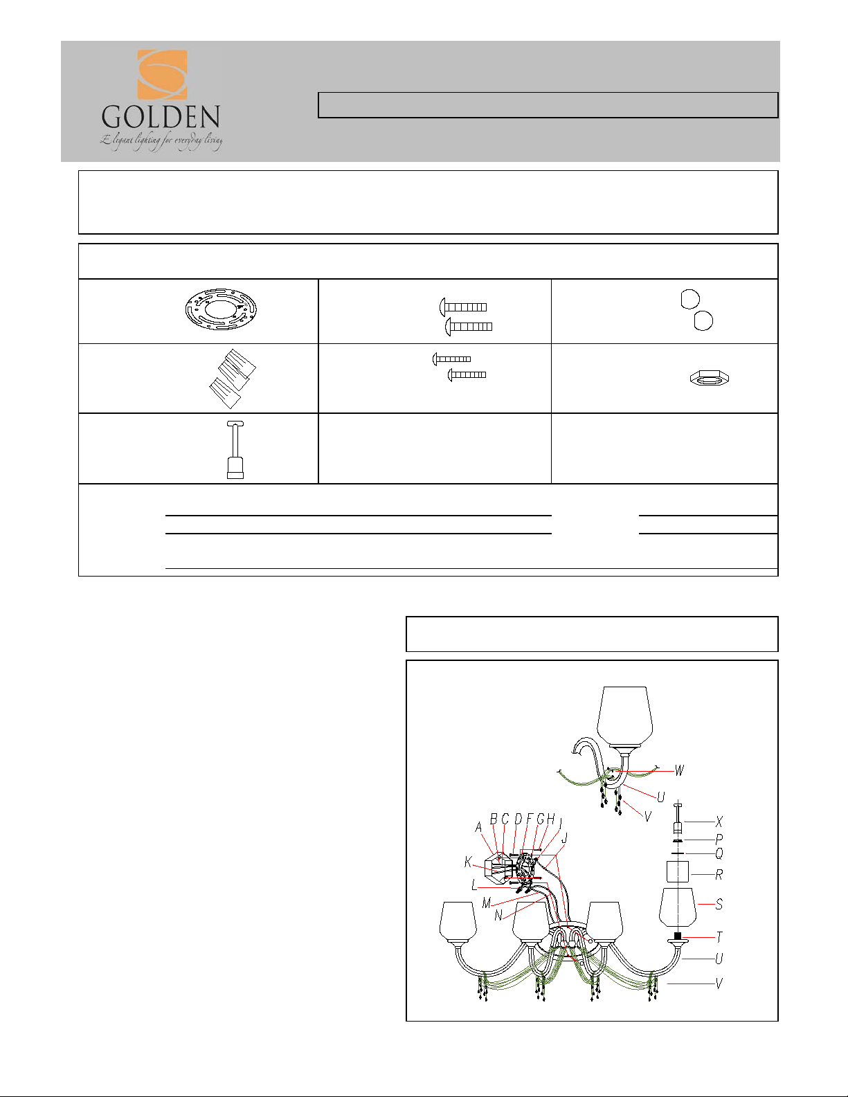
ASSEMBLING THE FIXTURE (Fig.1)
Socket Tool (X).
Fig 1
PARTS & ASSEMBLY SHEET
This fixture assembled PO:__________ Date: _ ____ ___
Company Name:_______________________Co. Account #:_____________
to be filled out by retailer
Fixture Name: Sancerre 1054-BA4 W G
Notice: Please review the parts listing and check for all parts before assembling the fixture. If any parts are
missing or damaged, please note onthis sheet and contact th e place of purchase t o arrange for replacement
parts.
PARTS LIST
Mounting Strap Mounting Screws Deco Nut
1ea ∅4"*H2mm 2ea 8#32-IP*1" 2ea 8#32-IP*H9mm
Wire connectors Mounting Screws Hex Nut
3ea P3 Orange 2ea 8#32-IP*1" 2ea 8#32-IP*H3mm
Socket Tool
1ea 1-1/8"*3-5/8"
Part Needed Quantity
Part Needed Quantity
Reason why ( missing, scratched, broken glass, bent, bad finish)
Comments
FIXTURE ASSEMBLY INSTRUCTIONS
do not install before assembling the fixture.
1. Crystal Chains (T) are individually wrapped and
must be hung piece by piece. Remove Crystal
Chain (T) from the packaging and examine the
chain for Connection Pin (U). Drape Crystal Chain
(T) over Arm (S) so that Connection Pin (U) sits on
top of Arm (S). This will ensure proper draping
length.
2. Install outer, Clear Glass (S) and inner, Opal
Glass (R) by sliding both pieces of glass over
Socket (T). Place Gasket (Q) inside Opal Glass (R)
and over Socket (T). Secure glass in place by
tightening Socket Ring (P) over Socket (T), using
1425-BA4 WG
Note: To avoid broken glass, do not over tighten
Socket Ring (P).
NOTE: INSTALL THE GLASS ASSEMBLY
AFTER THE FIXTURE IS HUNG.
Page 2

For Customer Service, contact the place of purchase to arrange for replacement parts.
Page 3

Fig. 1
Fig. 2
5. Attach Mounting Strap (F) to the Junction Box using the two mounting
screws (H) and tighten securely with screw driver.
INSTALLATION INSTRUCTIONS
HANGING THE FIXTURE (Fig.1)
illustrations and the Parts and Assembly Sheet.
wall, including the old mounting strap.
and secure with Hex Nut (G).
Screws (D) are vertical or horizontal, as required by fixture type.
CONNECTING THE WIRES (Fig 2)
BLACK to BLACK (or SMOOTH) and WHITE to WHITE (or RIBBED).
connector (L) onto the wires.
8. Tuck these wire connections neatly into the Junction Box.
FINISHING THE INSTALLATION(Fig.3)
over the two Mounting Screws (D) until tight as shown on Fig.1.
sheet.
Fig. 3
Fixture Name: Sancerre 1425-BA4 WG
WARNING ! SHUT OFF POWER AT FUSE OR CIRCUIT BREAKER.
1. Carefully remove the new fixture from the carton and the yellow bag that
holds all your parts. Check that all parts are included as shown in the
2. Shut off power at the circuit breaker and remove the old fixture from
3. Mounting Strap (F) contains several pairs of threaded holes. Find the
pair of holes that matches the holes spacing in your fixture Back Plate (H)
and thread the two Mounting Screws (D) half way into Mounting Strap (F)
4. Place Mounting Strap (F) over Junction Box (A) so that Mounting
For Wall Mount Light Fixture
6. Attach the power supply wires to the fixture lead wires by connecting
7. Attach the GROUND wire (GREEN or COPPER) from the Junction Box
and the fixture Ground wire to the green Ground Screw (I) on Mounting
Bracket (F) or connect both wires together using the correct size of wire
connectors. -
NOTE:Twist the wires together in the same direction you twist the wire
9. After tucking these wire connections neatly into the Junction Box and
placing the fixture Back Plate (E) over the two Mounting Screws (D),
secure Back Plate (E) against the wall by threading two Deco Nuts (O)
10. Install the light bulbs and glass shade as per the fixture assembly
YOUR INSTALLATION IS NOW COMPLETE. RETURN POWER TO THE
JUNCTION BOX AND TEST THE FIXTURE.
For Customer Service, contact the place of purchase to arrange for replacement parts.
 Loading...